9.4.1: Waves and currents at the outer delta
- Page ID
- 16402
\( \newcommand{\vecs}[1]{\overset { \scriptstyle \rightharpoonup} {\mathbf{#1}} } \)
\( \newcommand{\vecd}[1]{\overset{-\!-\!\rightharpoonup}{\vphantom{a}\smash {#1}}} \)
\( \newcommand{\id}{\mathrm{id}}\) \( \newcommand{\Span}{\mathrm{span}}\)
( \newcommand{\kernel}{\mathrm{null}\,}\) \( \newcommand{\range}{\mathrm{range}\,}\)
\( \newcommand{\RealPart}{\mathrm{Re}}\) \( \newcommand{\ImaginaryPart}{\mathrm{Im}}\)
\( \newcommand{\Argument}{\mathrm{Arg}}\) \( \newcommand{\norm}[1]{\| #1 \|}\)
\( \newcommand{\inner}[2]{\langle #1, #2 \rangle}\)
\( \newcommand{\Span}{\mathrm{span}}\)
\( \newcommand{\id}{\mathrm{id}}\)
\( \newcommand{\Span}{\mathrm{span}}\)
\( \newcommand{\kernel}{\mathrm{null}\,}\)
\( \newcommand{\range}{\mathrm{range}\,}\)
\( \newcommand{\RealPart}{\mathrm{Re}}\)
\( \newcommand{\ImaginaryPart}{\mathrm{Im}}\)
\( \newcommand{\Argument}{\mathrm{Arg}}\)
\( \newcommand{\norm}[1]{\| #1 \|}\)
\( \newcommand{\inner}[2]{\langle #1, #2 \rangle}\)
\( \newcommand{\Span}{\mathrm{span}}\) \( \newcommand{\AA}{\unicode[.8,0]{x212B}}\)
\( \newcommand{\vectorA}[1]{\vec{#1}} % arrow\)
\( \newcommand{\vectorAt}[1]{\vec{\text{#1}}} % arrow\)
\( \newcommand{\vectorB}[1]{\overset { \scriptstyle \rightharpoonup} {\mathbf{#1}} } \)
\( \newcommand{\vectorC}[1]{\textbf{#1}} \)
\( \newcommand{\vectorD}[1]{\overrightarrow{#1}} \)
\( \newcommand{\vectorDt}[1]{\overrightarrow{\text{#1}}} \)
\( \newcommand{\vectE}[1]{\overset{-\!-\!\rightharpoonup}{\vphantom{a}\smash{\mathbf {#1}}}} \)
\( \newcommand{\vecs}[1]{\overset { \scriptstyle \rightharpoonup} {\mathbf{#1}} } \)
\( \newcommand{\vecd}[1]{\overset{-\!-\!\rightharpoonup}{\vphantom{a}\smash {#1}}} \)
\(\newcommand{\avec}{\mathbf a}\) \(\newcommand{\bvec}{\mathbf b}\) \(\newcommand{\cvec}{\mathbf c}\) \(\newcommand{\dvec}{\mathbf d}\) \(\newcommand{\dtil}{\widetilde{\mathbf d}}\) \(\newcommand{\evec}{\mathbf e}\) \(\newcommand{\fvec}{\mathbf f}\) \(\newcommand{\nvec}{\mathbf n}\) \(\newcommand{\pvec}{\mathbf p}\) \(\newcommand{\qvec}{\mathbf q}\) \(\newcommand{\svec}{\mathbf s}\) \(\newcommand{\tvec}{\mathbf t}\) \(\newcommand{\uvec}{\mathbf u}\) \(\newcommand{\vvec}{\mathbf v}\) \(\newcommand{\wvec}{\mathbf w}\) \(\newcommand{\xvec}{\mathbf x}\) \(\newcommand{\yvec}{\mathbf y}\) \(\newcommand{\zvec}{\mathbf z}\) \(\newcommand{\rvec}{\mathbf r}\) \(\newcommand{\mvec}{\mathbf m}\) \(\newcommand{\zerovec}{\mathbf 0}\) \(\newcommand{\onevec}{\mathbf 1}\) \(\newcommand{\real}{\mathbb R}\) \(\newcommand{\twovec}[2]{\left[\begin{array}{r}#1 \\ #2 \end{array}\right]}\) \(\newcommand{\ctwovec}[2]{\left[\begin{array}{c}#1 \\ #2 \end{array}\right]}\) \(\newcommand{\threevec}[3]{\left[\begin{array}{r}#1 \\ #2 \\ #3 \end{array}\right]}\) \(\newcommand{\cthreevec}[3]{\left[\begin{array}{c}#1 \\ #2 \\ #3 \end{array}\right]}\) \(\newcommand{\fourvec}[4]{\left[\begin{array}{r}#1 \\ #2 \\ #3 \\ #4 \end{array}\right]}\) \(\newcommand{\cfourvec}[4]{\left[\begin{array}{c}#1 \\ #2 \\ #3 \\ #4 \end{array}\right]}\) \(\newcommand{\fivevec}[5]{\left[\begin{array}{r}#1 \\ #2 \\ #3 \\ #4 \\ #5 \\ \end{array}\right]}\) \(\newcommand{\cfivevec}[5]{\left[\begin{array}{c}#1 \\ #2 \\ #3 \\ #4 \\ #5 \\ \end{array}\right]}\) \(\newcommand{\mattwo}[4]{\left[\begin{array}{rr}#1 \amp #2 \\ #3 \amp #4 \\ \end{array}\right]}\) \(\newcommand{\laspan}[1]{\text{Span}\{#1\}}\) \(\newcommand{\bcal}{\cal B}\) \(\newcommand{\ccal}{\cal C}\) \(\newcommand{\scal}{\cal S}\) \(\newcommand{\wcal}{\cal W}\) \(\newcommand{\ecal}{\cal E}\) \(\newcommand{\coords}[2]{\left\{#1\right\}_{#2}}\) \(\newcommand{\gray}[1]{\color{gray}{#1}}\) \(\newcommand{\lgray}[1]{\color{lightgray}{#1}}\) \(\newcommand{\rank}{\operatorname{rank}}\) \(\newcommand{\row}{\text{Row}}\) \(\newcommand{\col}{\text{Col}}\) \(\renewcommand{\row}{\text{Row}}\) \(\newcommand{\nul}{\text{Nul}}\) \(\newcommand{\var}{\text{Var}}\) \(\newcommand{\corr}{\text{corr}}\) \(\newcommand{\len}[1]{\left|#1\right|}\) \(\newcommand{\bbar}{\overline{\bvec}}\) \(\newcommand{\bhat}{\widehat{\bvec}}\) \(\newcommand{\bperp}{\bvec^\perp}\) \(\newcommand{\xhat}{\widehat{\xvec}}\) \(\newcommand{\vhat}{\widehat{\vvec}}\) \(\newcommand{\uhat}{\widehat{\uvec}}\) \(\newcommand{\what}{\widehat{\wvec}}\) \(\newcommand{\Sighat}{\widehat{\Sigma}}\) \(\newcommand{\lt}{<}\) \(\newcommand{\gt}{>}\) \(\newcommand{\amp}{&}\) \(\definecolor{fillinmathshade}{gray}{0.9}\)We can safely state that the morphology of the outer delta is highly complicated and variable. This means that waves and currents encounter a very complex bed topography, with length scales which are not much larger than the wavelength of wind waves or swell, for instance. Via refraction, diffraction and reflection, this can lead to complex wave patterns with a strong spatial variability.
The currents in the vicinity of a tidal inlet are partly tidal, partly wave-driven, and partly wind-driven. The tidal currents are primarily concentrated in the main channels, the wave-driven currents in areas where waves are breaking. Wind-driven currents occur mainly during storm events and are therefore rather episodic, but nonetheless important (though often forgotten!).
Wave patterns

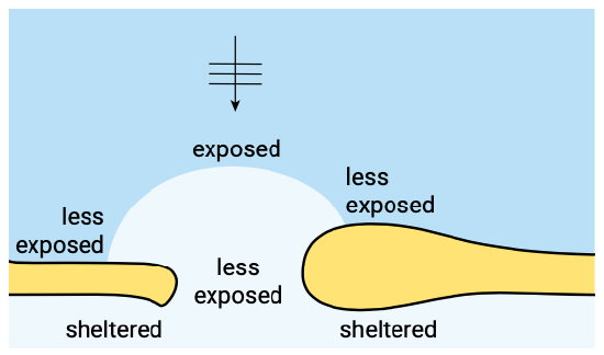
As to the overall pattern of the waves, there are a few points of consideration, such as the penetration of wave energy into the gorge and the sheltering from wave exposure in various parts of the system. Let us consider a typical inlet between two barrier islands, representative of one of the Wadden Sea inlets. In the case of normally incident waves, the entire delta edge and the gorge are exposed to wave energy. Due to refraction, the wave crests turn to become more and more parallel to the depth contours. Therefore, wave energy is concentrated in the central front edge of the ebb-tidal delta whereas the side lobes of the delta will be less exposed than the central front part. Due to breaking on the shoals of the outer delta, the gorge will also be less exposed (Fig. 9.10).

In the case of obliquely incident waves, one side lobe will be exposed, and the other will be sheltered. By implication, the wave climate at the sheltered side lobe will be different from that offshore or at the front edge of the delta. The western lobe in Fig. 9.11, for instance, will be fully exposed to westerly waves, less exposed (due to refraction) to northerly waves and sheltered from easterly waves. As a consequence, wave-driven longshore currents in the vicinity of this western lobe are predominantly eastbound. Similarly, the currents near the eastern lobe are predominantly westbound.
Another aspect which deserves attention is the wave penetration into the inlet. Clearly, the barrier islands provide considerable shelter to the basin, but wave energy can penetrate through the gorge. The latter, however, is sheltered to a certain extent from the open sea by the outer delta. Hence, the wave energy which reaches the back of the gorge is much less than offshore. Subsequently, this energy usually radiates into the basin, where the energy density and the wave height rapidly decay. As a consequence, the wave energy which penetrates from the open sea into the basin is usually rather small and it is restricted to the area right behind the gorge. Wave energy further into the basin is generally due to waves generated inside the basin, if the prevailing wind meets a sufficiently long fetch.

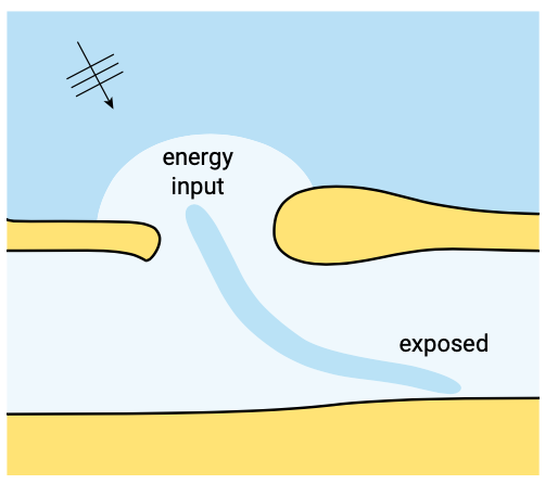
A drastically different situation may arise if channelling of the wave energy occurs (Fig. 9.12). This phenomenon is associated with trapping of the waves in the channel if the wave ray direction is almost parallel to the banks. In such a case, areas which are at first sight sheltered from sea waves can be exposed to relatively high wave energy and thus to much more erosion than expected.
The complexity of the bed topography and the mixture of sea/swell waves coming from offshore and locally generated waves of a much shorter period inside the basin make wave modelling for tidal inlets particularly difficult. A model for long-crested monochromatic waves (i.e. wave fields with one direction, one period and one height in each point of the model domain) will not work here. Instead, one would need a wave model, which allows for irregular, short-crested waves of various periods and includes wave generation. Such (often fully spectral) wave models have been available for some time for deep-water wave prediction, but this concept has been translated only relatively recently to shallower water.
Tidal residual currents
In Sect. 5.7.6 we already discussed the tidal residual flow pattern as a result of the accelerating flow through the inlet gorge. The tidal residual current pattern in the highly schematised situation discussed there boils down to a quadruplet of gyres, two at either side of the inlet (Fig. 5.74 ). In reality, the residual current picture is much more complicated than this. There is usually a distinct ebb-dominated current (i.e. averaged over the tide the flow is in the ebb-direction) over the outer delta, and often there are flood channels near the tips of the islands. In the Wadden Sea, well-developed flood deltas are hardly found (the entire basin acts as a flood delta, and the corresponding flood-residual current is difficult to distinguish). Many inlets on the East Coast of the USA, however, do exhibit such a feature and have a well-developed residual circulation inside the inlet.
Another type of residual current is the Stokes’ drift (Sect. 5.7.6) which is dependent on the phase-coupling between the horizontal and the vertical tide. It was shown that if the horizontal tide and the vertical tide are more or less in phase (\(\varphi \approx 0\)), there can be a considerable residual current. This becomes even more apparent for shoals bordering a tidal channel which are flooding and drying during the tide. There, the largest part of the flooded stage coincides with the flood tide, so there must be a flood-dominated residual current (averaged over the tide the flow is in the flood-direction). By implication, the residual current in the channel must be ebb-dominated.

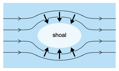
Secondary flow components can arise from amongst others the curvature of the tidal current (Sect. 5.7.6). The curvature-induced secondary flow does not change sign as the tide turns and is therefore in the upper part of the water column always directed away from the centre of curvature of the flow, in the lower part always towards it. Thus the curvature-induced secondary flow contributes, for instance, to the maintenance of shoals (see Fig. 9.13).

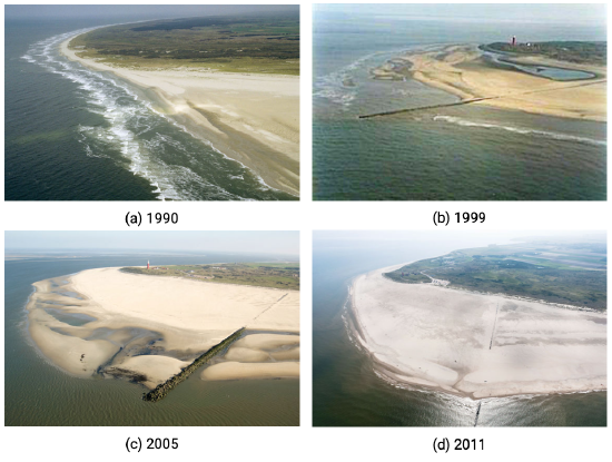
Curvature-induced secondary flow on an outer delta has been hypothesised to play an important role in the case of the groyne, which was built in 1995 to protect the north part of the coast of Texel, one of the barrier islands of the Dutch Wadden Sea (Fig. 9.14). The idea was to let this groyne interrupt the longshore drift into the inlet called Eierlandse Gat. Studies with 2D depth-averaged models (thus not resolving secondary flow patterns) revealed that this would lead to the ‘textbook-’pattern of updrift accretion and downdrift erosion, so to strong erosion north of the groyne. It was foreseen that the groyne would have to be connected by a hard structure to the existing revetment which protects the tip of the island. Once the groyne had been built, however, accretion occurred at either side of it Fig. 9.14, to the effect that it is now largely buried in sand (so the project turns out to be extremely successful, although at the cost of other coastal elements). Based on amongst others model computations by Steijn et al. (1998) this has been attributed to a large extent to the curvature-induced secondary flow in the gully around the tip of the groyne, which consistently brings sediment towards the groyne (see Fig. 9.14). However, new computations suggest that the ebb tidal currents during spring tides rather than the secondary flow is responsible for the large amounts of sedimentation at the north side of the dam (see Visser, 2014).
In summary, there is a variety of mechanisms which lead to tidal residual currents, and hence to residual sediment transports and morphological changes. In shallow areas such as a tidal inlet, we have to give up thinking of the tide as a small-amplitude wave.
Wave-induced currents
As stated before, an outer delta is nowhere near a straight prismatic coast. This means that the way of thinking about wave-driven currents as used in Ch. 5 is hardly applicable here. In that chapter, the alongshore and cross-shore momentum equations were separated, the former describing the momentum balance for a uniform longshore current and the latter the set-up balance. In the case of a complex topography with interrupted breaking, however, the situation is much more complicated; the momentum equations cannot be separated and need to be resolved in two horizontal dimensions; in principle, the wave-driven current in this type of situation is 3-D. A relatively simple example, a shoal on which waves are breaking, was already given in Sect. 5.5.7 (Fig. 5.49). The general pattern was a net flow in the wave direction over the shoal, turning seaward again via the channels between the shoals. In tidal inlets, the wave-driven currents around shoals on the outer delta can be so strong that they dominate the tidal residual currents. This has strong implications for the sediment bypassing mechanism, see Sect. 9.4.2.
Wind-induced currents
An often forgotten type of currents in tidal inlets are the wind-driven currents, either directly, via the wind-induced shear stress on the water surface in the inlet area, or indirectly, via the set-up of the water level against the coast. This means that the wind shear stress components need to be added to the depth-averaged momentum equations. These wind stress terms have the water depth in the denominator, which means that the wind tends to be more effective in driving a current when it acts on shallower water. Due to the large variations in water depth which are inherent to a tidal inlet, the wind-driven current field will therefore strongly vary in space. In general, the flow will tend to follow the wind in the shallower parts, and to oppose it in the deeper parts, but this picture can be complicated greatly by spatial interactions via water level gradients.
As the wind forcing acts at the water surface, there will also be an effect on the vertical structure of the flow: the primary flow profile (e.g. logarithmic) will be disturbed by a ‘secondary’ flow component which follows the wind in the upper part of the water column and goes against it in the lower part. Note that this secondary flow has to be superimposed on the primary flow (the depth-averaged circulation with a primary flow profile). The result can be a complex 3-D flow pattern.
Probably even more important than the direct wind-induced forcing is the effect of the water level set-up during a severe storm (Sect. 5.6). Although the peak of the wind speed usually does not last much more than a few hours, the water level set-up can last much longer. However, it takes time for the back-barrier basin to follow the water level in the open sea, as raising the water level of such a basin by a few metres takes huge amounts of water, all of which has to be squeezed in through the inlets. Hence it sometimes occurs that the ebb current is entirely suppressed and that there is a flood current in the inlet throughout a day or more. Clearly, such events may influence the inlet morphology considerably. It is also clear that new inlets and channels will preferentially be created under such conditions, when there is a large head difference between the sea and the basin.
3D combined current field
In summary, we have seen that the current field around an inlet is essentially more complex than on a uniform straight coast, and that all constituents of this field are essentially 3-D. So when modelling currents around inlets, we have to think 3-D, even if we decide to use a 2-D depth-averaged model. The interpretation and post-processing of the results (e.g. bed shear stress to be put into the sediment transport model) is much less straightforward here.
Wave-current interaction
The tidal and wave-driven current pattern on the outer delta is largely concentrated in the deeper channels. Consequently, there can be strong currents which affect the wave propagation via current refraction (see Sect. 5.2.3). This may even go as far as wave blocking (for a wave with opposing current). When standing on the coast overlooking a tidal inlet, one often observes a sharp distinction between areas with waves and areas with a flat water surface. This is simply because the current is strong enough to prevent the waves from entering this area. Moreover, where waves do occur, their pattern is often quite irregular, again as a consequence of refraction on a strongly varying current field. This form of wave-current interaction makes it particularly difficult to predict the wave field on the outer delta. Such a prediction should be based on a combined wave and current model, and both should be carefully calibrated in order to find the right pattern.
A more straightforward form of wave-current interaction is the effect of waves on bottom shear stress experienced by the current (see Sect. 5.5.5 and Sect. 6.5). The mechanisms underlying this effect are not essentially different from those in the case of a prismatic coast, though waves and near-bed currents can have arbitrary directions now. The result is a complex 3-D boundary layer with a strongly veering velocity vector and a non-trivial direction of the bed shear stress. In large-scale models like the ones we use for tidal inlets, however, the effect on the direction is usually ignored and the shear stress is assumed to be opposite to the mean current. What we do have to take into account, however, is the bed shear stress enhancement induced by the waves. This may have major effects on the current pattern: especially the tidal flow will tend to avoid shallow areas, where wave action and shear stress enhancement are strongest.


