5.7.6: Residual currents
- Page ID
- 16340
\( \newcommand{\vecs}[1]{\overset { \scriptstyle \rightharpoonup} {\mathbf{#1}} } \)
\( \newcommand{\vecd}[1]{\overset{-\!-\!\rightharpoonup}{\vphantom{a}\smash {#1}}} \)
\( \newcommand{\id}{\mathrm{id}}\) \( \newcommand{\Span}{\mathrm{span}}\)
( \newcommand{\kernel}{\mathrm{null}\,}\) \( \newcommand{\range}{\mathrm{range}\,}\)
\( \newcommand{\RealPart}{\mathrm{Re}}\) \( \newcommand{\ImaginaryPart}{\mathrm{Im}}\)
\( \newcommand{\Argument}{\mathrm{Arg}}\) \( \newcommand{\norm}[1]{\| #1 \|}\)
\( \newcommand{\inner}[2]{\langle #1, #2 \rangle}\)
\( \newcommand{\Span}{\mathrm{span}}\)
\( \newcommand{\id}{\mathrm{id}}\)
\( \newcommand{\Span}{\mathrm{span}}\)
\( \newcommand{\kernel}{\mathrm{null}\,}\)
\( \newcommand{\range}{\mathrm{range}\,}\)
\( \newcommand{\RealPart}{\mathrm{Re}}\)
\( \newcommand{\ImaginaryPart}{\mathrm{Im}}\)
\( \newcommand{\Argument}{\mathrm{Arg}}\)
\( \newcommand{\norm}[1]{\| #1 \|}\)
\( \newcommand{\inner}[2]{\langle #1, #2 \rangle}\)
\( \newcommand{\Span}{\mathrm{span}}\) \( \newcommand{\AA}{\unicode[.8,0]{x212B}}\)
\( \newcommand{\vectorA}[1]{\vec{#1}} % arrow\)
\( \newcommand{\vectorAt}[1]{\vec{\text{#1}}} % arrow\)
\( \newcommand{\vectorB}[1]{\overset { \scriptstyle \rightharpoonup} {\mathbf{#1}} } \)
\( \newcommand{\vectorC}[1]{\textbf{#1}} \)
\( \newcommand{\vectorD}[1]{\overrightarrow{#1}} \)
\( \newcommand{\vectorDt}[1]{\overrightarrow{\text{#1}}} \)
\( \newcommand{\vectE}[1]{\overset{-\!-\!\rightharpoonup}{\vphantom{a}\smash{\mathbf {#1}}}} \)
\( \newcommand{\vecs}[1]{\overset { \scriptstyle \rightharpoonup} {\mathbf{#1}} } \)
\( \newcommand{\vecd}[1]{\overset{-\!-\!\rightharpoonup}{\vphantom{a}\smash {#1}}} \)
\(\newcommand{\avec}{\mathbf a}\) \(\newcommand{\bvec}{\mathbf b}\) \(\newcommand{\cvec}{\mathbf c}\) \(\newcommand{\dvec}{\mathbf d}\) \(\newcommand{\dtil}{\widetilde{\mathbf d}}\) \(\newcommand{\evec}{\mathbf e}\) \(\newcommand{\fvec}{\mathbf f}\) \(\newcommand{\nvec}{\mathbf n}\) \(\newcommand{\pvec}{\mathbf p}\) \(\newcommand{\qvec}{\mathbf q}\) \(\newcommand{\svec}{\mathbf s}\) \(\newcommand{\tvec}{\mathbf t}\) \(\newcommand{\uvec}{\mathbf u}\) \(\newcommand{\vvec}{\mathbf v}\) \(\newcommand{\wvec}{\mathbf w}\) \(\newcommand{\xvec}{\mathbf x}\) \(\newcommand{\yvec}{\mathbf y}\) \(\newcommand{\zvec}{\mathbf z}\) \(\newcommand{\rvec}{\mathbf r}\) \(\newcommand{\mvec}{\mathbf m}\) \(\newcommand{\zerovec}{\mathbf 0}\) \(\newcommand{\onevec}{\mathbf 1}\) \(\newcommand{\real}{\mathbb R}\) \(\newcommand{\twovec}[2]{\left[\begin{array}{r}#1 \\ #2 \end{array}\right]}\) \(\newcommand{\ctwovec}[2]{\left[\begin{array}{c}#1 \\ #2 \end{array}\right]}\) \(\newcommand{\threevec}[3]{\left[\begin{array}{r}#1 \\ #2 \\ #3 \end{array}\right]}\) \(\newcommand{\cthreevec}[3]{\left[\begin{array}{c}#1 \\ #2 \\ #3 \end{array}\right]}\) \(\newcommand{\fourvec}[4]{\left[\begin{array}{r}#1 \\ #2 \\ #3 \\ #4 \end{array}\right]}\) \(\newcommand{\cfourvec}[4]{\left[\begin{array}{c}#1 \\ #2 \\ #3 \\ #4 \end{array}\right]}\) \(\newcommand{\fivevec}[5]{\left[\begin{array}{r}#1 \\ #2 \\ #3 \\ #4 \\ #5 \\ \end{array}\right]}\) \(\newcommand{\cfivevec}[5]{\left[\begin{array}{c}#1 \\ #2 \\ #3 \\ #4 \\ #5 \\ \end{array}\right]}\) \(\newcommand{\mattwo}[4]{\left[\begin{array}{rr}#1 \amp #2 \\ #3 \amp #4 \\ \end{array}\right]}\) \(\newcommand{\laspan}[1]{\text{Span}\{#1\}}\) \(\newcommand{\bcal}{\cal B}\) \(\newcommand{\ccal}{\cal C}\) \(\newcommand{\scal}{\cal S}\) \(\newcommand{\wcal}{\cal W}\) \(\newcommand{\ecal}{\cal E}\) \(\newcommand{\coords}[2]{\left\{#1\right\}_{#2}}\) \(\newcommand{\gray}[1]{\color{gray}{#1}}\) \(\newcommand{\lgray}[1]{\color{lightgray}{#1}}\) \(\newcommand{\rank}{\operatorname{rank}}\) \(\newcommand{\row}{\text{Row}}\) \(\newcommand{\col}{\text{Col}}\) \(\renewcommand{\row}{\text{Row}}\) \(\newcommand{\nul}{\text{Nul}}\) \(\newcommand{\var}{\text{Var}}\) \(\newcommand{\corr}{\text{corr}}\) \(\newcommand{\len}[1]{\left|#1\right|}\) \(\newcommand{\bbar}{\overline{\bvec}}\) \(\newcommand{\bhat}{\widehat{\bvec}}\) \(\newcommand{\bperp}{\bvec^\perp}\) \(\newcommand{\xhat}{\widehat{\xvec}}\) \(\newcommand{\vhat}{\widehat{\vvec}}\) \(\newcommand{\uhat}{\widehat{\uvec}}\) \(\newcommand{\what}{\widehat{\wvec}}\) \(\newcommand{\Sighat}{\widehat{\Sigma}}\) \(\newcommand{\lt}{<}\) \(\newcommand{\gt}{>}\) \(\newcommand{\amp}{&}\) \(\definecolor{fillinmathshade}{gray}{0.9}\)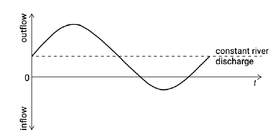
River discharge is the most obvious source of a net tide-averaged flow velocity and discharge (see Fig. 5.72).
In the absence of river discharge or other nontidal forcing (e.g. wind), the net tide-averaged discharge should be zero. Nevertheless, vertical or horizontal circulation currents and residual currents may exist. For instance, an irregular coastline or a headland can induce residual currents, in pretty much the same way as the long dam in Sect. 5.7.2. Other processes and mechanisms are treated below.
The relevance of these residual currents and secondary flows to the sediment transport and the bed topography is described in Ch. 9.
Tidal residual current pattern in an inlet gorge
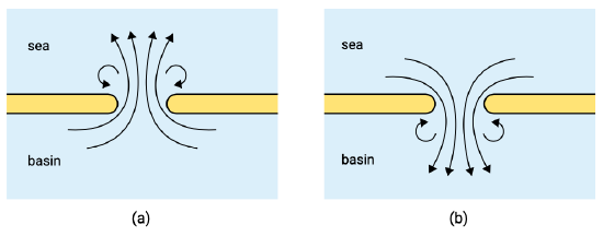
Figure 5.73: Outgoing tidal jet (a) and ingoing tidal jet (b).
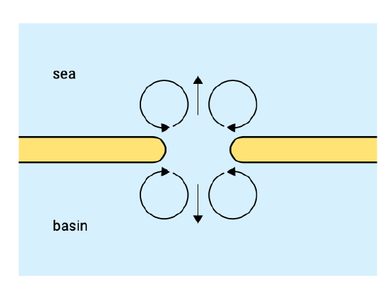
Figure 5.74: Schematised tidal residual currents around an inlet.
An important physical mechanism to bear in mind when interpreting the tidal currents is inertia. The tidal flow in an inlet gorge has so much momentum that it cannot spread out fast enough when leaving the gorge: it forms a tidal jet. The length scale of such a tidal jet is a few hundred times the water depth, so a few kilometres. On the other hand, the water flowing into the gorge has to accelerate and is therefore inertia-dominated, i.e. close to potential flow. This means that the highest velocities coincide with the shortest path through the gorge, i.e. just around the tips of the islands (Fig. 5.73). The tidal residual current pattern in this highly schematised situation boils down to a quadruplet of gyres, two at either side of the inlet (Fig. 5.74).
Stokes’ drift
As for wind waves (Sect. 5.5.1) a Stokes’ drift or mass flux is associated with tidal propagation of an at least partly progressive tidal wave. A Stokes’ drift in the direction of tidal propagation will occur if more than half of the flood tide coincides with water levels above the tidal cycle mean water level. The corresponding inflow of water must for a closed basin be compensated by an opposing outgoing flow, much like the undertow (Sect. 5.5.1).
The magnitude is dependent on the phase coupling between the horizontal and the vertical tide. Suppose \(u\) is the tidal current velocity in a 1-D channel, \(h\) the mean water depth and \(\eta\) the water surface elevation above mean sea level, and let \(u\) and \(\eta\) be given by:
\[\eta = a \sin (\omega t - kx) \text{ and } u = \hat{u} \sin ( \omega t - kx - \varphi)\]
The tidal residual flux of water is then given by (compare with Eq. 5.5.1.2):
\[q_{res} = \hat{u} a \dfrac{1}{T} \int_{0}^{T} \sin (\omega t - kx - \varphi ) \sin (\omega t - kx)dt = \dfrac{1}{2} \hat{u} a \cos \varphi\]
Thus, if the horizontal tide (\(u\)) and the vertical tide (\(\eta\)) are \(90^{\circ}\) out of phase (\(\varphi = -\pi /2\)), there is no residual flux. But if they are more or less in phase (\(\varphi \approx 0^{\circ}\)), there can be a considerable residual current.
Bathymetry-induced residual current
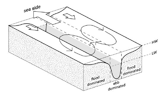
If a cross-section of a channel consists of deeper and shallower sections, the residual flow in the deeper channels is usually in the ebb-direction, whereas in the shallower parts it is in the flood-direction. This leads to a net (averaged over the tidal cycle) flood current in the shallower section and a net ebb current in the deeper sections, as indicated schematically in Fig. 5.75.
Coriolis-induced residual current and secondary flow
Due to Coriolis, the flood and ebb flow in a basin tend to be concentrated along opposite banks: the flood flow more along the right bank, viewed from the flood flow direction and the ebb flow more along the right bank, viewed from the ebb flow direction (in a Northern Hemisphere basin). Averaged over the tide, this may give rise to residual flood and ebb currents. In a confined channel that prevents a deviation of the course, the Coriolis force is balanced, in a depth-averaged sense, by a water level (pressure) gradient (see Intermezzo 3.6). Compare this with the cross-shore force balance between a water level gradient due to set-up and the wave forces in the surf zone (Sect. 5.5.4). As in the cross-shore profile, the channel prevents a depth-mean transversal velocity. The depth-distribution of the Coriolis force is determined by the velocity profile (e.g. logarithmic) along the channel axis (see Eq. \(\ref{eq5.7.6.3}\)). Thus, the depth-distribution of the Coriolis and pressure forces are different (compare Fig. 5.43), resulting in a secondary circulation in the channel cross-section (hence in the vertical plane). Since the Coriolis force changes sign at ebb and flood, the effect is neutral in a tide-averaged sense.
Curvature-induced and Coriolis-induced secondary flow
In river bends, a secondary circulation occurs perpendicular to the main flow direction. Closer to the bottom it is directed towards the inner bend and closer to the surface towards the outer bend. In tidal channels a similar curvature-induced circulation can be found. The curvature-induced secondary flow pattern is the result of different depth-distributions of pressure and curvature-induced centrifugal forces, analogous to the above described Coriolis-induced circulation. The curvature-induced flow, however, does not change sign as the tide turns. In the following, we will combine both effects.
A simple description is obtained when the assumption is adopted that the flow (both ebb and flood) has adapted to the channel bend under the influence of bottom friction and mean surface slope (pressure gradient) and that both the channel and flow structure are angle independent in a cylindrical coordinate system. The transversal (perpendicular to the mean flow) force balance then reads:
\[\underbrace{-\dfrac{u^2}{R}}_{\text{centrifugal force}} + \underbrace{fu}_{\text{Coriolis}} + \underbrace{\dfrac{1}{\rho} \dfrac{\partial p}{\partial y}}_{\text{pressure gradient}} - \underbrace{\dfrac{\partial }{\partial z} v_T \dfrac{\partial v}{\partial z}}_{\text{turbulent viscosity}} = 0\label{eq5.7.6.3}\]
where:
| \(R\) | radius of the channel bend (assumed to be much larger than the channel width) | \(m\) |
| \(u\) | local velocity along the channel axis | \(m/s\) |
| \(x\) | lateral coordinate \(x = R \theta\) | \(m\) |
| \(z\) | vertical coordinate; bottom: \(z = -h\), surface \(z = \eta\) | \(m\) |
| \(v\) | transversal coordinate | \(m\) |
| \(v_T\) | eddy viscosity | \(m^2/s\) |
If stratification (density differences) is neglected, the transversal pressure gradient \(\partial p /\partial y = \rho g \partial \eta /\partial y\) is due to the water level slope, counteracting the centrifugal and Coriolis forces. The equation describes the evolution of a transversal circulation current \(v\) due to the vertical shear in the lateral channel flow \(u\). The bend radius \(R\) is an important factor in determining the relative importance of the centrifugal force and the Coriolis force. The Coriolis contribution changes sign at ebb and flood; the centrifugal force exerts its influence at ebb and flood in the same direction.
In a depth-averaged sense and neglecting the bed shear stress due to the transversal circulation, the centrifugal forces and Coriolis force are balanced by a water level gradient. As above, a circulation current arises, since the depth-distribution of the various forces is different (see the first two terms in Eq. \(\ref{eq5.7.6.3}\)) that are determined by the velocity profile along the channel axis).
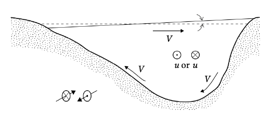
By twice integrating the force balance Eq. \(\ref{eq5.7.6.3}\)) over depth, it is possible to derive an expression for the transversal circulation current. Near the bottom this circulation is towards the inner bend (tide-averaged, see Fig. 5.76). The Coriolis acceleration strengthens the transversal circulation when from the perspective of the main flow the channel outer bend is a right bank (i.e. at ebb and flood this implies opposite bends, and this holds for the Northern Hemisphere). The transversal circulation gives the tidal flow a spiralling character.


