5.5.7: 3D effects
- Page ID
- 16332
\( \newcommand{\vecs}[1]{\overset { \scriptstyle \rightharpoonup} {\mathbf{#1}} } \)
\( \newcommand{\vecd}[1]{\overset{-\!-\!\rightharpoonup}{\vphantom{a}\smash {#1}}} \)
\( \newcommand{\id}{\mathrm{id}}\) \( \newcommand{\Span}{\mathrm{span}}\)
( \newcommand{\kernel}{\mathrm{null}\,}\) \( \newcommand{\range}{\mathrm{range}\,}\)
\( \newcommand{\RealPart}{\mathrm{Re}}\) \( \newcommand{\ImaginaryPart}{\mathrm{Im}}\)
\( \newcommand{\Argument}{\mathrm{Arg}}\) \( \newcommand{\norm}[1]{\| #1 \|}\)
\( \newcommand{\inner}[2]{\langle #1, #2 \rangle}\)
\( \newcommand{\Span}{\mathrm{span}}\)
\( \newcommand{\id}{\mathrm{id}}\)
\( \newcommand{\Span}{\mathrm{span}}\)
\( \newcommand{\kernel}{\mathrm{null}\,}\)
\( \newcommand{\range}{\mathrm{range}\,}\)
\( \newcommand{\RealPart}{\mathrm{Re}}\)
\( \newcommand{\ImaginaryPart}{\mathrm{Im}}\)
\( \newcommand{\Argument}{\mathrm{Arg}}\)
\( \newcommand{\norm}[1]{\| #1 \|}\)
\( \newcommand{\inner}[2]{\langle #1, #2 \rangle}\)
\( \newcommand{\Span}{\mathrm{span}}\) \( \newcommand{\AA}{\unicode[.8,0]{x212B}}\)
\( \newcommand{\vectorA}[1]{\vec{#1}} % arrow\)
\( \newcommand{\vectorAt}[1]{\vec{\text{#1}}} % arrow\)
\( \newcommand{\vectorB}[1]{\overset { \scriptstyle \rightharpoonup} {\mathbf{#1}} } \)
\( \newcommand{\vectorC}[1]{\textbf{#1}} \)
\( \newcommand{\vectorD}[1]{\overrightarrow{#1}} \)
\( \newcommand{\vectorDt}[1]{\overrightarrow{\text{#1}}} \)
\( \newcommand{\vectE}[1]{\overset{-\!-\!\rightharpoonup}{\vphantom{a}\smash{\mathbf {#1}}}} \)
\( \newcommand{\vecs}[1]{\overset { \scriptstyle \rightharpoonup} {\mathbf{#1}} } \)
\( \newcommand{\vecd}[1]{\overset{-\!-\!\rightharpoonup}{\vphantom{a}\smash {#1}}} \)
\(\newcommand{\avec}{\mathbf a}\) \(\newcommand{\bvec}{\mathbf b}\) \(\newcommand{\cvec}{\mathbf c}\) \(\newcommand{\dvec}{\mathbf d}\) \(\newcommand{\dtil}{\widetilde{\mathbf d}}\) \(\newcommand{\evec}{\mathbf e}\) \(\newcommand{\fvec}{\mathbf f}\) \(\newcommand{\nvec}{\mathbf n}\) \(\newcommand{\pvec}{\mathbf p}\) \(\newcommand{\qvec}{\mathbf q}\) \(\newcommand{\svec}{\mathbf s}\) \(\newcommand{\tvec}{\mathbf t}\) \(\newcommand{\uvec}{\mathbf u}\) \(\newcommand{\vvec}{\mathbf v}\) \(\newcommand{\wvec}{\mathbf w}\) \(\newcommand{\xvec}{\mathbf x}\) \(\newcommand{\yvec}{\mathbf y}\) \(\newcommand{\zvec}{\mathbf z}\) \(\newcommand{\rvec}{\mathbf r}\) \(\newcommand{\mvec}{\mathbf m}\) \(\newcommand{\zerovec}{\mathbf 0}\) \(\newcommand{\onevec}{\mathbf 1}\) \(\newcommand{\real}{\mathbb R}\) \(\newcommand{\twovec}[2]{\left[\begin{array}{r}#1 \\ #2 \end{array}\right]}\) \(\newcommand{\ctwovec}[2]{\left[\begin{array}{c}#1 \\ #2 \end{array}\right]}\) \(\newcommand{\threevec}[3]{\left[\begin{array}{r}#1 \\ #2 \\ #3 \end{array}\right]}\) \(\newcommand{\cthreevec}[3]{\left[\begin{array}{c}#1 \\ #2 \\ #3 \end{array}\right]}\) \(\newcommand{\fourvec}[4]{\left[\begin{array}{r}#1 \\ #2 \\ #3 \\ #4 \end{array}\right]}\) \(\newcommand{\cfourvec}[4]{\left[\begin{array}{c}#1 \\ #2 \\ #3 \\ #4 \end{array}\right]}\) \(\newcommand{\fivevec}[5]{\left[\begin{array}{r}#1 \\ #2 \\ #3 \\ #4 \\ #5 \\ \end{array}\right]}\) \(\newcommand{\cfivevec}[5]{\left[\begin{array}{c}#1 \\ #2 \\ #3 \\ #4 \\ #5 \\ \end{array}\right]}\) \(\newcommand{\mattwo}[4]{\left[\begin{array}{rr}#1 \amp #2 \\ #3 \amp #4 \\ \end{array}\right]}\) \(\newcommand{\laspan}[1]{\text{Span}\{#1\}}\) \(\newcommand{\bcal}{\cal B}\) \(\newcommand{\ccal}{\cal C}\) \(\newcommand{\scal}{\cal S}\) \(\newcommand{\wcal}{\cal W}\) \(\newcommand{\ecal}{\cal E}\) \(\newcommand{\coords}[2]{\left\{#1\right\}_{#2}}\) \(\newcommand{\gray}[1]{\color{gray}{#1}}\) \(\newcommand{\lgray}[1]{\color{lightgray}{#1}}\) \(\newcommand{\rank}{\operatorname{rank}}\) \(\newcommand{\row}{\text{Row}}\) \(\newcommand{\col}{\text{Col}}\) \(\renewcommand{\row}{\text{Row}}\) \(\newcommand{\nul}{\text{Nul}}\) \(\newcommand{\var}{\text{Var}}\) \(\newcommand{\corr}{\text{corr}}\) \(\newcommand{\len}[1]{\left|#1\right|}\) \(\newcommand{\bbar}{\overline{\bvec}}\) \(\newcommand{\bhat}{\widehat{\bvec}}\) \(\newcommand{\bperp}{\bvec^\perp}\) \(\newcommand{\xhat}{\widehat{\xvec}}\) \(\newcommand{\vhat}{\widehat{\vvec}}\) \(\newcommand{\uhat}{\widehat{\uvec}}\) \(\newcommand{\what}{\widehat{\wvec}}\) \(\newcommand{\Sighat}{\widehat{\Sigma}}\) \(\newcommand{\lt}{<}\) \(\newcommand{\gt}{>}\) \(\newcommand{\amp}{&}\) \(\definecolor{fillinmathshade}{gray}{0.9}\)So far, we considered situations without alongshore variations. For various reasons however, wave conditions can vary along a certain stretch of coast; for instance due to wave refraction on a non-uniform near-shore region or due to wave diffraction in the lee side of structures. Wave-induced forces will vary according to changes in the wave conditions and the terms \(\partial S_{xx} /\partial y\) and \(\partial S_{xy} /\partial y\) may be non-zero in Eqs. 5.5.3.1 and 5.5.3.3. Variations in wave height along a coastline create variations in cross-shore wave forces along the coast and hence in wave set-ups. Consequently, pressure gradients \(\rho g h \partial \bar{\eta}/\partial y\) occur along the coast and 3D current patterns are the result. We will briefly discuss the following situations:
- Eddy formation in the shadow zone of structures;
- Creation of rip currents;
- 3D current patterns around shoals.
Eddy formation in the shadow zone of structures
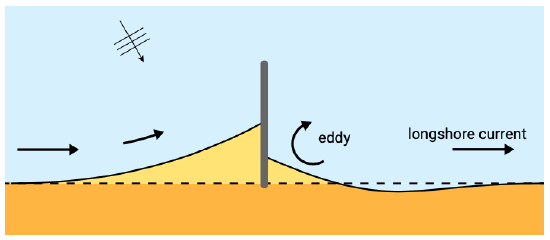
In the case of wave sheltering due to for instance groynes or detached breakwaters, wave set-up can be expected to be less in the sheltered area than in the unsheltered region. This generates local near-shore currents towards the sheltered area. Figure 5.45 shows the situation of a groyne. In the shadow zone of the groyne due to set-up differences a current runs towards the groyne until it is diverted outward along the structure creating an eddy.
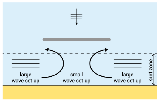
In Fig. 5.46 set-up differences create near-shore currents towards the sheltered zone from both sides of the detached (emerged) breakwater. Continuity requires that water leaves the area as well. Therefore a return flow will be present in deeper water resulting in the development of two eddies. A characteristic flow pattern is generated (see Fig. 5.46).
Rip currents due to convergence or divergence of wave energy
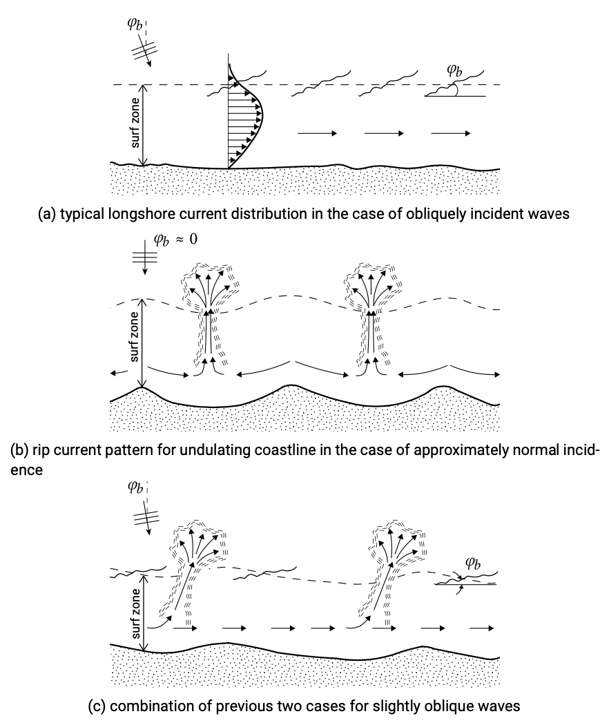
Rip currents are strong, narrow currents that flow seaward from the surf zone. They are fed by longshore directed surf zone currents that turn seaward to form a rip current. The longshore currents are generated by set-up differences and run from the position of the highest set-up towards the position of the lowest set-up. The alongshore variation in wave set-up can be generated by convergence and divergence of wave energy due to depth-refraction or sheltering effects due to for instance headlands. An undulating coastline gives concentration of wave energy towards the undulations due to depth-refraction (Fig. 5.47b). The longshore currents run from the position of the highest waves and hence highest set-up to the position of the lowest waves. In this way a rhythmic pattern of rip currents is generated. Such a situation will only be able to develop for nearly normal incidence; in the case of obliquely incident waves, a longshore current driven by gradients in radiation shear stress (Fig. 5.47a) will overshadow the more subtle effects of set-up differences. A combination of the two effects may occur for slightly oblique wave incidence (Fig. 5.47c).
Wave-induced currents around shoals (and submerged breakwaters)
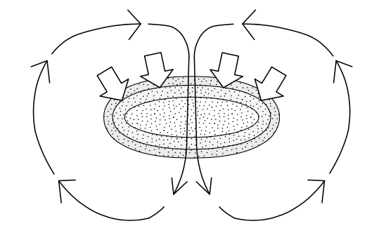
In the case of a complex topography with interrupted breaking, the pattern of wave-induced currents is more complicated. A still relatively simple example concerns a shoal on which waves are breaking (Fig. 5.48). Due to refraction, the waves will tend to converge toward the top of the shoal. As the waves break on the seaward slope of the shoal, they generate a dissipation related wave force. At the top of the shoal there is no closed boundary requiring a zero mean flow. Instead, the water will flow over the shoal in the direction of the force. The water flows over the shoal until it reaches the channel behind the shoal, where water level gradients will deflect it and drive it to the sides of the shoal. There it has room to flow seawards again, thus closing the circulation. In tidal inlets the wave-driven currents around shoals on the outer delta can be so strong that they dominate the tidal residual currents (see Sect. 9.4.1).
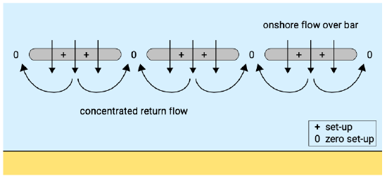
In a similar fashion, the interruption of wave breaking can generate rip currents along a stretch of coast. Non-homogeneous wave breaking can occur in the case of a non-homogeneous alongshore bar system or a (series of) submerged breakwater(s) on which waves break, see Fig. 5.49. (Partial) wave breaking on the bar induces a set-up over the bar as well as an onshore flow. Water level gradients and continuity force the flow to deflect to the sides and return seaward in between the breakwaters or bars in a concentrated rip current.


