5.6: Thermo-Diagram Applications
- Page ID
- 9558
\( \newcommand{\vecs}[1]{\overset { \scriptstyle \rightharpoonup} {\mathbf{#1}} } \)
\( \newcommand{\vecd}[1]{\overset{-\!-\!\rightharpoonup}{\vphantom{a}\smash {#1}}} \)
\( \newcommand{\dsum}{\displaystyle\sum\limits} \)
\( \newcommand{\dint}{\displaystyle\int\limits} \)
\( \newcommand{\dlim}{\displaystyle\lim\limits} \)
\( \newcommand{\id}{\mathrm{id}}\) \( \newcommand{\Span}{\mathrm{span}}\)
( \newcommand{\kernel}{\mathrm{null}\,}\) \( \newcommand{\range}{\mathrm{range}\,}\)
\( \newcommand{\RealPart}{\mathrm{Re}}\) \( \newcommand{\ImaginaryPart}{\mathrm{Im}}\)
\( \newcommand{\Argument}{\mathrm{Arg}}\) \( \newcommand{\norm}[1]{\| #1 \|}\)
\( \newcommand{\inner}[2]{\langle #1, #2 \rangle}\)
\( \newcommand{\Span}{\mathrm{span}}\)
\( \newcommand{\id}{\mathrm{id}}\)
\( \newcommand{\Span}{\mathrm{span}}\)
\( \newcommand{\kernel}{\mathrm{null}\,}\)
\( \newcommand{\range}{\mathrm{range}\,}\)
\( \newcommand{\RealPart}{\mathrm{Re}}\)
\( \newcommand{\ImaginaryPart}{\mathrm{Im}}\)
\( \newcommand{\Argument}{\mathrm{Arg}}\)
\( \newcommand{\norm}[1]{\| #1 \|}\)
\( \newcommand{\inner}[2]{\langle #1, #2 \rangle}\)
\( \newcommand{\Span}{\mathrm{span}}\) \( \newcommand{\AA}{\unicode[.8,0]{x212B}}\)
\( \newcommand{\vectorA}[1]{\vec{#1}} % arrow\)
\( \newcommand{\vectorAt}[1]{\vec{\text{#1}}} % arrow\)
\( \newcommand{\vectorB}[1]{\overset { \scriptstyle \rightharpoonup} {\mathbf{#1}} } \)
\( \newcommand{\vectorC}[1]{\textbf{#1}} \)
\( \newcommand{\vectorD}[1]{\overrightarrow{#1}} \)
\( \newcommand{\vectorDt}[1]{\overrightarrow{\text{#1}}} \)
\( \newcommand{\vectE}[1]{\overset{-\!-\!\rightharpoonup}{\vphantom{a}\smash{\mathbf {#1}}}} \)
\( \newcommand{\vecs}[1]{\overset { \scriptstyle \rightharpoonup} {\mathbf{#1}} } \)
\(\newcommand{\longvect}{\overrightarrow}\)
\( \newcommand{\vecd}[1]{\overset{-\!-\!\rightharpoonup}{\vphantom{a}\smash {#1}}} \)
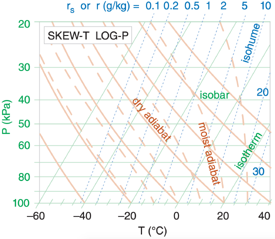
\(\newcommand{\avec}{\mathbf a}\) \(\newcommand{\bvec}{\mathbf b}\) \(\newcommand{\cvec}{\mathbf c}\) \(\newcommand{\dvec}{\mathbf d}\) \(\newcommand{\dtil}{\widetilde{\mathbf d}}\) \(\newcommand{\evec}{\mathbf e}\) \(\newcommand{\fvec}{\mathbf f}\) \(\newcommand{\nvec}{\mathbf n}\) \(\newcommand{\pvec}{\mathbf p}\) \(\newcommand{\qvec}{\mathbf q}\) \(\newcommand{\svec}{\mathbf s}\) \(\newcommand{\tvec}{\mathbf t}\) \(\newcommand{\uvec}{\mathbf u}\) \(\newcommand{\vvec}{\mathbf v}\) \(\newcommand{\wvec}{\mathbf w}\) \(\newcommand{\xvec}{\mathbf x}\) \(\newcommand{\yvec}{\mathbf y}\) \(\newcommand{\zvec}{\mathbf z}\) \(\newcommand{\rvec}{\mathbf r}\) \(\newcommand{\mvec}{\mathbf m}\) \(\newcommand{\zerovec}{\mathbf 0}\) \(\newcommand{\onevec}{\mathbf 1}\) \(\newcommand{\real}{\mathbb R}\) \(\newcommand{\twovec}[2]{\left[\begin{array}{r}#1 \\ #2 \end{array}\right]}\) \(\newcommand{\ctwovec}[2]{\left[\begin{array}{c}#1 \\ #2 \end{array}\right]}\) \(\newcommand{\threevec}[3]{\left[\begin{array}{r}#1 \\ #2 \\ #3 \end{array}\right]}\) \(\newcommand{\cthreevec}[3]{\left[\begin{array}{c}#1 \\ #2 \\ #3 \end{array}\right]}\) \(\newcommand{\fourvec}[4]{\left[\begin{array}{r}#1 \\ #2 \\ #3 \\ #4 \end{array}\right]}\) \(\newcommand{\cfourvec}[4]{\left[\begin{array}{c}#1 \\ #2 \\ #3 \\ #4 \end{array}\right]}\) \(\newcommand{\fivevec}[5]{\left[\begin{array}{r}#1 \\ #2 \\ #3 \\ #4 \\ #5 \\ \end{array}\right]}\) \(\newcommand{\cfivevec}[5]{\left[\begin{array}{c}#1 \\ #2 \\ #3 \\ #4 \\ #5 \\ \end{array}\right]}\) \(\newcommand{\mattwo}[4]{\left[\begin{array}{rr}#1 \amp #2 \\ #3 \amp #4 \\ \end{array}\right]}\) \(\newcommand{\laspan}[1]{\text{Span}\{#1\}}\) \(\newcommand{\bcal}{\cal B}\) \(\newcommand{\ccal}{\cal C}\) \(\newcommand{\scal}{\cal S}\) \(\newcommand{\wcal}{\cal W}\) \(\newcommand{\ecal}{\cal E}\) \(\newcommand{\coords}[2]{\left\{#1\right\}_{#2}}\) \(\newcommand{\gray}[1]{\color{gray}{#1}}\) \(\newcommand{\lgray}[1]{\color{lightgray}{#1}}\) \(\newcommand{\rank}{\operatorname{rank}}\) \(\newcommand{\row}{\text{Row}}\) \(\newcommand{\col}{\text{Col}}\) \(\renewcommand{\row}{\text{Row}}\) \(\newcommand{\nul}{\text{Nul}}\) \(\newcommand{\var}{\text{Var}}\) \(\newcommand{\corr}{\text{corr}}\) \(\newcommand{\len}[1]{\left|#1\right|}\) \(\newcommand{\bbar}{\overline{\bvec}}\) \(\newcommand{\bhat}{\widehat{\bvec}}\) \(\newcommand{\bperp}{\bvec^\perp}\) \(\newcommand{\xhat}{\widehat{\xvec}}\) \(\newcommand{\vhat}{\widehat{\vvec}}\) \(\newcommand{\uhat}{\widehat{\uvec}}\) \(\newcommand{\what}{\widehat{\wvec}}\) \(\newcommand{\Sighat}{\widehat{\Sigma}}\) \(\newcommand{\lt}{<}\) \(\newcommand{\gt}{>}\) \(\newcommand{\amp}{&}\) \(\definecolor{fillinmathshade}{gray}{0.9}\)Figure 5.6 shows a simplified, Skew-T diagram. We use this as the common background for the demonstrations that follow.
5.5.1. Thermodynamic State
You need three points on a thermodynamic diagram to indicate air-parcel state (pressure, temperature, humidity). For this one air parcel at one height, all three points are always plotted on the same isobar (P).
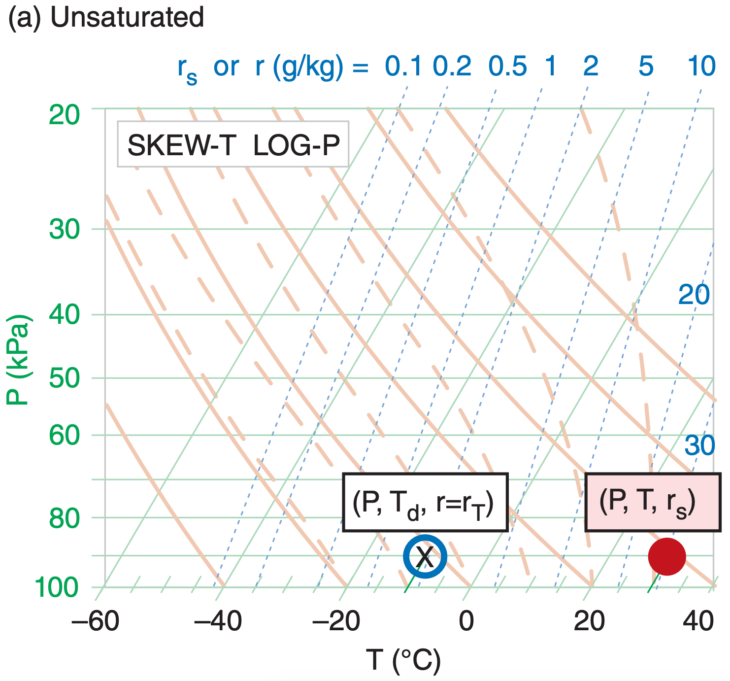
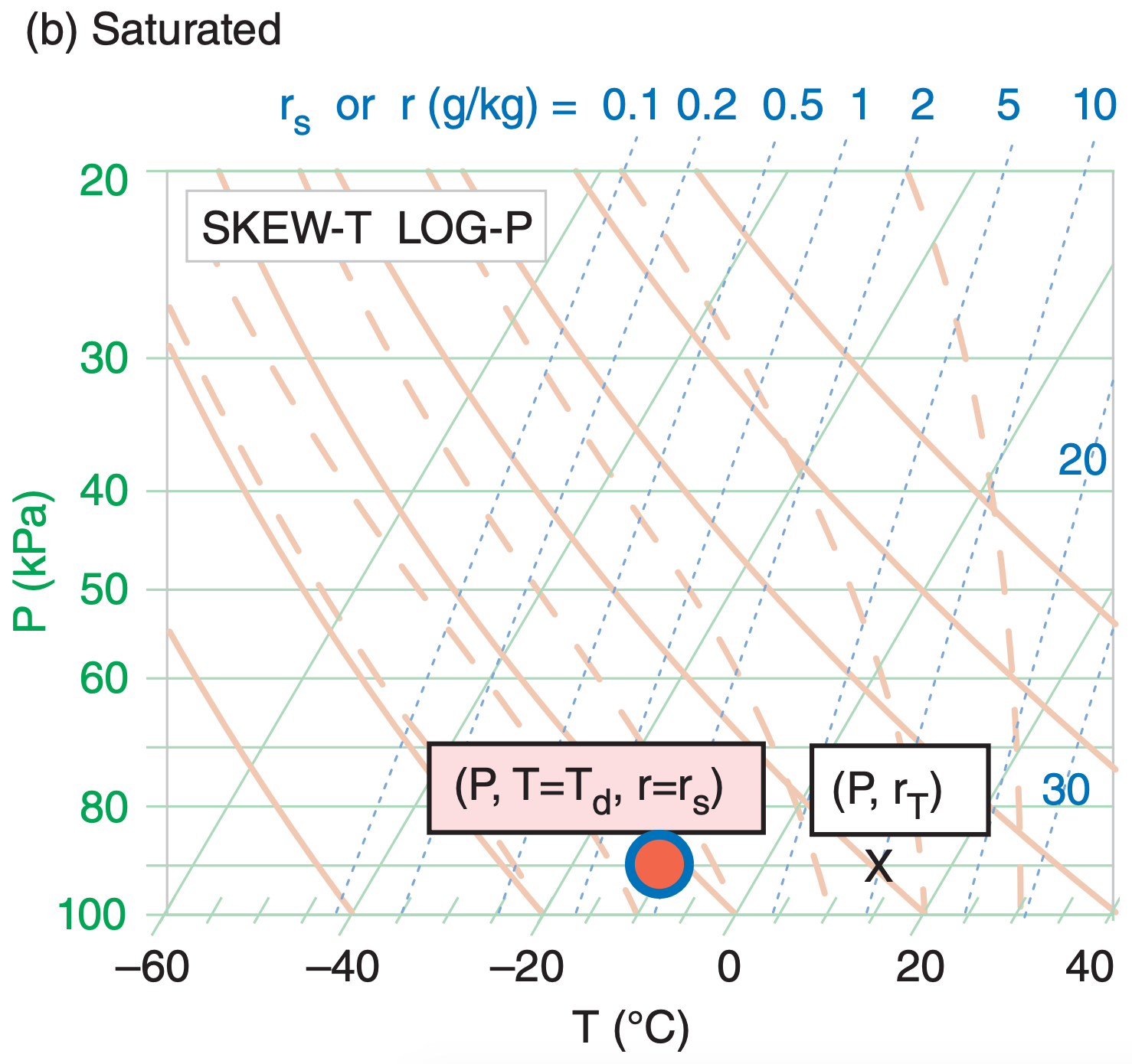
One point represents T, the actual air temperature (red dot; red filled circle in Figure 5.7). Its coordinates in the thermo diagram are given by (P, T, rs). Note that rs is redundant, because it can be determined from P and T. But we include it for convenience, because we use the rs value for many calculations.
Another point represents Td, the dew-point temperature (blue circle outline; no fill). Its coordinates are (P, Td, r). Again, r is redundant.
The third point gives rT, the total water mixing ratio in the air parcel (designated by “X” on the thermo diagram). Its coordinates are (P, rT).
Often, two of these three points coincide. One example is for unsaturated air (Figure 5.7a) with no rain falling through it. For this case, the temperature and dew-point circles are plotted as described above. However, the X is plotted inside the dew-point circle because the total water in the air parcel equals the water-vapor mixing ratio (rT = r), which is fully specified by the dew point. Namely, the isohume that passes through the dew-point circle indicates the actual amount of water vapor in the air, and there are no other phases of water in that air parcel.
The isohume that passes through the actual air temperature gives the saturation mixing ratio (rs, the maximum equilibrium amount of moisture that could be held as vapor). A separate symbol is NOT plotted on the thermo diagram for rs for two reasons. One, it does not indicate the actual state of the air parcel. Two, it is fully specified as the isohume that passes through the temperature point.
For saturated (cloudy or foggy) air parcels (Figure 5.7b), the two temperature points coincide (T = Td and r = rs). In this figure, the red-filled circle still represents air temperature, and the blue circle outline still represents the dew-point temperature (for water vapor). However, the total water X is usually to the right of the temperature circles, because clouds contain liquid water and/or ice in addition to water vapor. This is explained later.
[Tip: On these figures, we use large size circles and X’s to make them easier to see. However, when you plot them on your own thermo diagram, use smaller circles and X’s that you write very precisely on the diagram. Utilize colored pens or pencils if you have them.]
5.5.2. Processes
5.5.2.1. Unsaturated (Dry) Lifting
Suppose that an air parcel that is initially unsaturated rises without mixing with the surrounding environment, and with no radiative or other heat transfer to or from it. The rising air parcel cools at the dry adiabatic lapse rate, while carrying all the air and water molecules with it. For this case, mixing ratio (r) and potential temperature (θ) are constant.
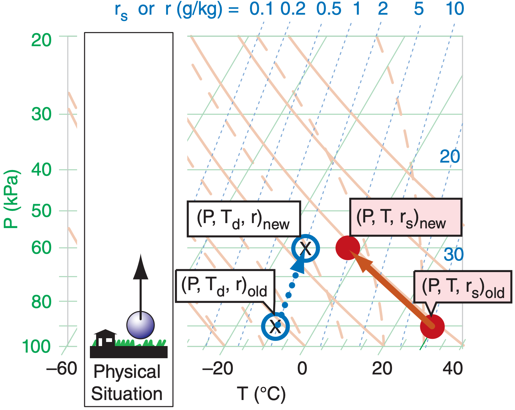
Starting from the initial state as plotted by the “old” points on the thermo diagram (Figure 5.8), determine which dry adiabat is under the center of the red filled circle (temperature), then move the red circle up along this adiabat. Similarly for moisture, determine which isohume is under the center of the blue hollow circle and “X”, and follow it up (keeping r constant). Always end the movement of all three points at the same new pressure.
If the points don’t lie directly on a drawn isopleth (which is usually the case), then imagine a new isopleth that goes through your point, and which is parallel to (and maintains its relative distance from) the neighboring drawn isopleths. You can do this by eye, or you may use a straight-edge to draw on the diagram a new isopleth that goes through your point of interest. Then, move the air parcel along this imaginary isopleth. Namely, move the temperature point in a direction parallel to the dry adiabats, and move the humidity point parallel to the isohumes.
Descending unsaturated (non-cloudy) air parcels behave similarly, except moving downward along their appropriate isopleths.
Sample Application
a) What are the values of pressure, temperature, total water mixing ratio, dew point, saturation mixing ratio, actual mixing ratio, and relative humidity of the “old” air parcel in Figure 5.8a before it starts to rise?
(b) Same question, but at its new altitude.
Find the Answer
Given: Use info in Figure 5.8 to answer this.
Find: P = ? kPa, T = ? °C, rT = ? g kg–1, Td = ? °C, rs = ? g kg–1, r = ? g kg–1, RH = ? %
(a) Get pressure from the isobar (horizontal green line) that passes through the center of both points. The pressure is displayed along the left side of the thermo diagram. P = 90 kPa.
Get temperature from the isotherm (green diagonal line) that passes through the center of the red dot. Follow that isotherm diagonally down to the bottom of the graph to read its value. T = 30°C.
Get total water mixing ratio from the isohume (dotted blue line) that passes through the “X”. Read the isohume value at the top of the graph. rT = 2 g kg–1.
Get the dew-point temperature from the isotherm (diagonal green line) that passes through the center of the open blue circle. Follow this line diagonally down to the bottom of the thermo diagram to read its label: Td = –10°C.
Get the saturation mixing ratio from the isohume (dotted blue line) that passes through the center of the red circle. It is labeled as: rs = 30 g kg–1.
Get the actual mixing ratio from the isohume (dotted blue line) that passes through the center of the open blue circle, and read the label at the top of the graph. r = 2gkg–1.
Relative humidity is not displayed on thermo diagrams. But you can find it from RH% = (100%)·(r/rs) = (100%)·(2/30) = 6.7% .
(b) Try this on your own, using the same procedure as described above but for the parcel at the new altitude in Figure 5.8, and then compare with my answers. P = 60 kPa, T = –3°C, rT = 2 g kg–1, Td = –15°C, rs = 5 g kg–1, r = 2 g kg–1, RH% = 40%.
Check: Physics and units are reasonable.
Exposition: Although the air was extremely dry initially, as the air parcel was lifted its relative humidity increased. How did this happen, even though the amount of water in the air (r = 2 g kg–1) did not change? The reason was that after the air parcel was lifted to its new altitude, it was much colder, and cold air has a smaller capacity to hold water vapor (rs decreased).
If you were to continue lifting the parcel, eventually it would cool to the point where rs = r, meaning that the air is saturated. The altitude where this happens indicates cloud base for convective clouds (clouds created by local updrafts of air).
You can get more accurate answers using larger thermo diagrams at the end of this chapter.
5.5.2.2. Saturated (Moist) Lifting & Liquid Water
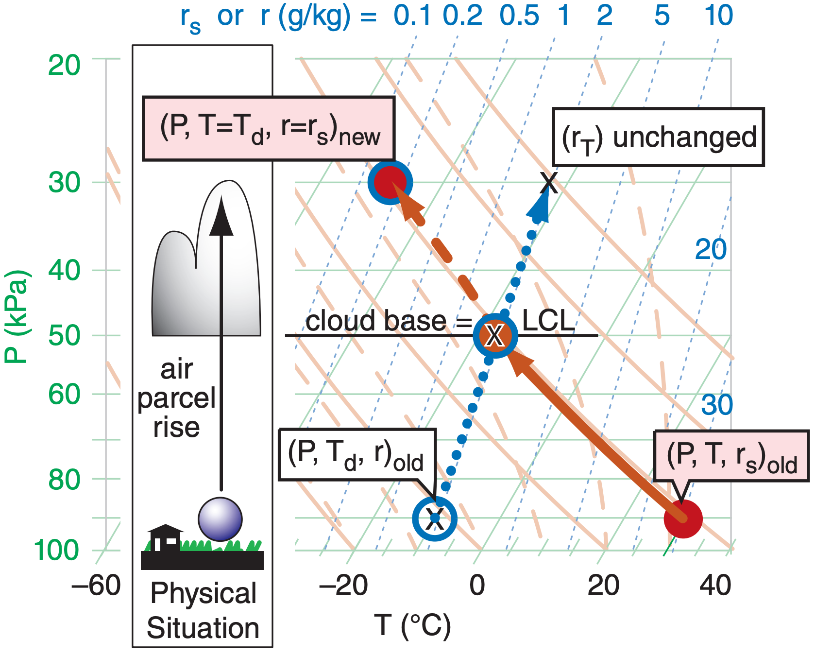
Notice in Figure 5.8 that the temperature and dewpoint curves for the air parcel get closer to each other as the parcel rises. Eventually the dry adiabat and isohume lines cross. The pressure or altitude where they cross (see Figure 5.9) is defined as the LCL (lifting condensation level), which marks cloud base height for convective clouds (clouds with updrafts from the local region under them, such as cumulus clouds and thunderstorms). This is the altitude where the rising air first becomes saturated — where Td = T, and r = rs = rT.
Above the LCL the blue circle (Td) and red dot (T) move together, along a saturated adiabat curve (the orange dashed line that goes through the LCL point). Since saturated air is holding all the vapor that it can, it also means that the actual mixing ratio r equals the saturation value rs.
If all the condensate (initially as tiny cloud droplets or ice crystals) continues to move with the air parcel and does not fall out as precipitation, then the total-water mixing ratio (rT) in the parcel is constant. It is easy to estimate the liquid-water mixing ratio (rL, the relative mass of cloud droplets) as the difference between the total water and the water vapor. In summary, for saturated (cloudy) air: T = Td, r = rs, and rL = rT – rs.
Cloudy descending air follows the same lines, but in reverse. Knowing the temperature (red dot with blue circle near the top of Figure 5.9) and total water content (“X” in that figure) inside the cloud at any one altitude or pressure, you can then follow the isohume (dotted blue line) down from the “X” and the saturated adiabat (dashed orange line) down from the initial temperature point. As the cloudy air parcel descends it is compressed and warms, allowing more and more of the cloud droplets to evaporate. Eventually, at the LCL, the last droplets have evaporated, so any further descent must follow the dry adiabat (solid orange line) and isohume (dotted blue line) in Figure 5.9. Namely, the blue circle and the red dot split apart below the LCL.
Sample Application
Use Figure 5.9 to estimate P, T, Td, r, rs, rT, rL or rice for the parcel: (a) at the LCL, and (b) at P = 30 kPa.
Find the Answer
Given: The dots, circles, and “X’s” in Figure 5.9.
Find: P= ? kPa, T = ?°C, Td = ?°C, r = ? g kg–1, rs = ? g kg–1, rT = ? g kg–1, rL = ? g kg–1
(a) At cloud base (i.e., at the LCL), Figure 5.9 indicates:
P= 50 kPa, T = –17°C, Td = –17°C, r = 2 g kg–1, rs = 2 g kg–1, rT = 2 g kg–1, rL = rT – rs = 0 g kg–1
(b) At cloud top (assuming no precipitation): P= 30 kPa, T = –48°C, Td = –48°C, r = 0.15 g kg–1, rs = 0.15 g kg–1, rT = 2 g kg–1, rice = rT – rs = 2.0 – 0.15 = 1.85 g kg–1
Check: Physics and units are reasonable.
Exposition: At temperatures below about –38°C, all hydrometeors are in the form of ice. This is good for aircraft, because ice crystals blow over the wings rather than sticking to them. However, some jet engines have problems when the ice crystals melt and re-freeze on the turbine blades, causing engine problems.
5.5.2.3. Precipitation
So far, we assumed that all the liquid water droplets stay inside (move with) the air parcel, meaning rT = constant. Namely, the “X” in Figure 5.9 says on one dotted blue line isohume. However, if some of the liquid drops or ice crystals precipitate out of the parcel, then rT decreases toward rs, and “X” shifts to a different isohume (Figure 5.10). The “X” reaches the blue circle (rT = rs ) if all the precipitation falls out.
After precipitation is finished, if there is subsequent ascent or descent, then you must follow the isohume (dotted blue line) that goes through the new location for “X” on the diagram.
Instead of losing water due to precipitation out of an air parcel, sometimes total water is gained when precipitation falls into a parcel from above. Regardless of whether precipitation adds or subtracts water, the process is irreversible, causing a change in the parcel’s LCL.
In Figure 5.10 we illustrate precipitation as happening only while the air parcel is at a fixed pressure or altitude. This is overly simple, as precipitation can also occur while the parcel rises or descends. One way to approximate this on a thermo diagram is to take short adiabatic changes in altitude, and then allow precipitation to occur after each step.
Sample Application
What if ice crystals falling out of the cloud-top air, as illustrated in Figure 5.10, reduced the total-water mixing ratio from 2 to 0.5 g kg–1. (a) What is its new thermodynamic state at P = 30 kPa? (b) What is its new PLCL if it were to then descend?
Find the Answer
Given: Figure 5.10, rT old = 2 g kg–1, and rnew = 0.5 g kg–1
Find: (a) P= ? kPa, T = ?°C, Td = ?°C, r = ? g kg–1, rs=? g kg–1, rT =? g kg–1, rice =? g kg–1, rprecip =? g kg–1
(b) PLCL = ? kPa.
(a) New state at cloud top after precipitation:
P= 30 kPa, T = –48°C, Td = –48°C, r = 0.15 g kg–1, rs = 0.15 g kg–1, rT = 0.5 g kg–1,
rice = rT – rs = 0.5 – 0.15 = 0.35 g kg–1
rprecip = 2 – 0.5 = 1.5 g kg–1 .
(b) New lifting condensation level (LCL):
In Figure 5.10, from the red dot follow the orangedashed saturated adiabat downward. (Since no orange dashed lines goes through the red dot, we need to interpolate between neighboring dashed lines left and right of the red dot). Also, from the X for the new rT = 0.5 g kg–1 value, follow the blue-dotted isohume downward. Where those two lines cross is the new LCL. Doing this on a thermo diagram (not shown) gives roughly PLCL = 37 kPa.
Check: Physics and units are reasonable.
Exposition: Note that the new LCL is at a higher altitude (lower pressure) than the LCL in Figure 5.9, because precipitation fallout left the air drier.
5.5.2.4. Radiative Heating/Cooling
In the infrared (IR) clouds are blackbodies. They absorb all the IR radiation incident on the outer surface of the cloud, and they emit IR radiation outward in all directions based on the temperature of the cloud droplets on that outer surface.
If the ground and/or atmosphere below cloud base is warmer than the cloud, then there will be more IR radiation absorbed by the cloud base than is re-emitted, and the cloud-base warms. At night, if the ground is colder than cloud base, then the cloud will emit more IR towards the ground than it absorbs, preventing the ground from cooling as much as it would under clear skies, but cooling cloud base.
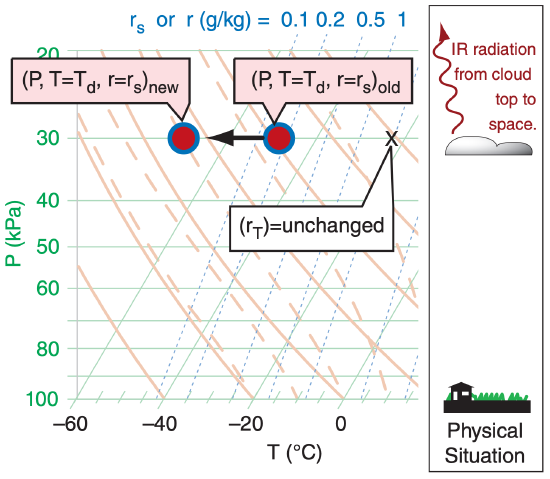
The atmosphere above the cloud is usually colder than the cloud, and the cloud also “sees” the near-absolute zero temperatures of outer space. Thus, cloud top cools by IR radiation all the time (night and day, see Figure 5.11). Such cooling creates cold “thermals” in the top 2 cm of cloud-top air that sink lower into the cloud and spread the cooling effect over more of the cloud. This same effect occurs in fog, which tends to make fog denser and more difficult to dissipate.
Sample Application
Suppose IR radiation caused the cloud-top thermodynamic state to change as shown in Figure 5.11, where Tnew ≈ –71°C and no precipitation falls out. What is the air parcel’s new thermodynamic state, and what will be its new PLCL?
Find the Answer
Given: data in Figure 5.11
Find: (a) P= ? kPa, T = ?°C, Td = ?°C, r = ? g kg–1, rs=? g kg–1, rT =? g kg–1, rice =? g kg–1, rprecip =? g kg–1
(b) PLCL = ? kPa.
(a) Approximate new state, base on visual interpretation of Figure 5.11:
P= 30 kPa, T = –71°C, Td = –71°C, r ≈ 0 g kg–1, rs ≈ 0 g kg–1, rT = 2.0 g kg–1, rice = rT – rs = 2 – 0 = 2 g kg–1
(b) New lifting condensation level (LCL):
In Figure 5.11, from the red dot follow the orangedashed saturated adiabat downward. Also, from the X for rT = 2 g kg–1 value, follow the blue-dotted isohume downward. Where those two lines cross is the new LCL. Doing this on a thermo diagram (such as Figure 5.11) gives roughly PLCL ≈ 80 kPa.
Check: Physics and units are reasonable.
Exposition: The lifting condensation level is at lower altitude (higher pressure) than it was originally.
NOTE: For this and for previous Sample Applications, you might find a slightly different answer if you used a different thermo diagram. This is normal. These slight differences in the new air-parcel state are usually neglected, because there is even greater uncertainty in measured old values of air-parcel state.
During daytime light from the sun can reach the clouds, where some is absorbed by the cloud droplets and some is scattered back out (making clouds appear white). The portion absorbed in the tops and sides of clouds is spread over a thicker regions of cloud that extends about 2 m into the cloud from the outer surface. This means that heating due to sunlight is spread over a thicker layer of cloud, as opposed to IR cooling which happens only at the immediate cloud surface.
Recall that the word “adiabatic” means no heat is transferred between the air parcel and the surrounding environment. Radiation is not adiabatic, and hence is called diabatic. In Figure 5.11, the diabatic IR cooling causes the red dot and blue circle to move together (T = Td) to colder temperatures, while the total-water mixing ratio “X” is unchanged because radiation does not create or destroy water molecules. Nonetheless, as temperature drops, rs (= r) decreases, causing liquid rL or solid rice water to increase (according to rL new or rice new = rT – rs new . ) in the absence of precipitation.
Solar heating of the cloud would cause diabatic warming on the thermo diagram.
Radiation is important in cloud evolution and cloud dynamics, particularly for the anvils of mesoscale convective systems (thunderstorms), hurricanes, and frontal stratus clouds (see the Clouds chapter).
Many systems in nature are in equilibrium as a result of a balance between opposing forcings. For such a system, if one of the forcings is changed, the system responds in a way to reach a new equilibrium that partially undoes the changed forcing.
In chemistry, this is known as LeChatelier’s Principle. For example, if two reagents are in equilibrium in a beaker, then if you add more of one of the reagents, a reaction occurs that reduces the concentration increase of the added reagent.
For global climate, the principle is known as homeostasis. For example, increased solar radiation will cause the earth-system temperature to increase, thereby causing increased cooling due to outgoing IR radiation (due to the Stefan-Boltzmann law) which partially compensates the original heating.
Many external influences (particularly solar heating) create instabilities in the atmosphere. The atmosphere responds by generating motions on a wide range of scales. These motions transport heat that partially undoes the effect of the external influence. We experience these responses as the global circulation, weather systems and storms.
Sample Application
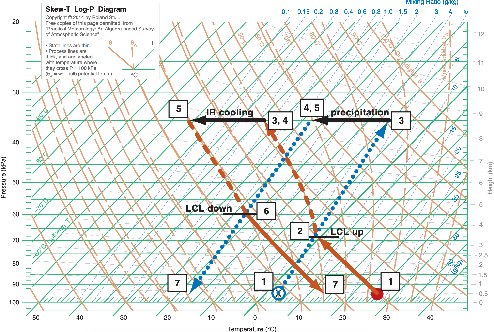
Suppose an air parcel has an initial state of (P, T, Td) = (95 kPa, 26°C, 3°C). It rises to an altitude where P = 35 kPa, which represents cloud top. While there, precipitation removes water amount ∆rT = 4 g kg–1, and IR cooling lowers the temperature by ∆T = –18°C. If the air parcel then returns back to its original pressure, what is its final thermodynamic state? Use the full-size skew-T from the end of this chapter for this exercise. Explain all steps.
Find the Answer
Given: (P, T, Td)initial = (95 kPa, 26°C, 3°C). Ptop = 35 kPa. ∆r = –4 g kg–1, and ∆T = –18°C.
Find: (P, T, Td )final = (95 kPa, ?°C, ?°C)
[1] The red dot and blue circle show the initial temperature and dew-point of the air parcel, respectively. Interpolating between the 4 and 6 g kg–1 isohumes, it appears that the initial dew point corresponds to roughly r ≈ 5 g kg–1 , which is plotted as the line with large blue dots with upward arrow.
[2] From [1] follow the dry adiabat for T (solid orange line), and follow the isohume for Td (dotted blue line). They cross at an LCL of about PLCL ≈ 68 kPa (given by the horizontal black line through that LCL point, and interpolating between the horizontal green lines to find the pressure). This is cloud base for ascending air.
[3] As the air parcel continues to rise to cloud top at P = 35 kPa, the temperature and dew-point follow the saturated adiabat (dashed orange line). Thus, at cloud top, T = Td ≈ –38°C (which is the isotherm (diagonal green line) that goes through temperature point [3] at the tip of the upward arrowhead. The total-water mixing ratio is conserved and still follows the 5 g kg–1 isohume.
[4] Precipitation removes 4 g kg–1 from the parcel, leaving rT = 5 –4 = 1 g kg–1 as indicated by the dotted blue isohume. But the parcel air temperature is unchanged from point [3].
[5] Infrared (IR) radiative cooling decreases the temperature by 18°C, causing a new cloud-top temperature of T = Td ≈ –38 – 18 = – 56°C. The corresponding rs value is so small that it is below 0.1 g kg–1 . But the total water content is unchanged from point [4].
[6] As this air is saturated (because rs < rT), the descent follows a saturated adiabat (dashed orange line) down to where the saturated adiabat crosses the isohume (dotted blue line). This intersection marks the LCL for descending air, which is at about PLCL = 60 kPa (interpolate between the horizontal green line to the black line through this point).
[7] Below this cloud base, T follows the dry adiabat (solid orange line), ending with T ≈ 14°C at P = 95 kPa. The dewpoint follows the 1 g kg–1 isohume (dotted blue line), giving a final Ts ≈ –17°C. (P, T, Td )final = (95 kPa, 14°C, –17°C)
