
8.4.3: Shadow effects due to obstacles away from the shoreline
- Page ID
- 16392

\( \newcommand{\vecs}[1]{\overset { \scriptstyle \rightharpoonup} {\mathbf{#1}} } \)
\( \newcommand{\vecd}[1]{\overset{-\!-\!\rightharpoonup}{\vphantom{a}\smash {#1}}} \)
\( \newcommand{\id}{\mathrm{id}}\) \( \newcommand{\Span}{\mathrm{span}}\)
( \newcommand{\kernel}{\mathrm{null}\,}\) \( \newcommand{\range}{\mathrm{range}\,}\)
\( \newcommand{\RealPart}{\mathrm{Re}}\) \( \newcommand{\ImaginaryPart}{\mathrm{Im}}\)
\( \newcommand{\Argument}{\mathrm{Arg}}\) \( \newcommand{\norm}[1]{\| #1 \|}\)
\( \newcommand{\inner}[2]{\langle #1, #2 \rangle}\)
\( \newcommand{\Span}{\mathrm{span}}\)
\( \newcommand{\id}{\mathrm{id}}\)
\( \newcommand{\Span}{\mathrm{span}}\)
\( \newcommand{\kernel}{\mathrm{null}\,}\)
\( \newcommand{\range}{\mathrm{range}\,}\)
\( \newcommand{\RealPart}{\mathrm{Re}}\)
\( \newcommand{\ImaginaryPart}{\mathrm{Im}}\)
\( \newcommand{\Argument}{\mathrm{Arg}}\)
\( \newcommand{\norm}[1]{\| #1 \|}\)
\( \newcommand{\inner}[2]{\langle #1, #2 \rangle}\)
\( \newcommand{\Span}{\mathrm{span}}\) \( \newcommand{\AA}{\unicode[.8,0]{x212B}}\)
\( \newcommand{\vectorA}[1]{\vec{#1}} % arrow\)
\( \newcommand{\vectorAt}[1]{\vec{\text{#1}}} % arrow\)
\( \newcommand{\vectorB}[1]{\overset { \scriptstyle \rightharpoonup} {\mathbf{#1}} } \)
\( \newcommand{\vectorC}[1]{\textbf{#1}} \)
\( \newcommand{\vectorD}[1]{\overrightarrow{#1}} \)
\( \newcommand{\vectorDt}[1]{\overrightarrow{\text{#1}}} \)
\( \newcommand{\vectE}[1]{\overset{-\!-\!\rightharpoonup}{\vphantom{a}\smash{\mathbf {#1}}}} \)
\( \newcommand{\vecs}[1]{\overset { \scriptstyle \rightharpoonup} {\mathbf{#1}} } \)
\( \newcommand{\vecd}[1]{\overset{-\!-\!\rightharpoonup}{\vphantom{a}\smash {#1}}} \)
\(\newcommand{\avec}{\mathbf a}\) \(\newcommand{\bvec}{\mathbf b}\) \(\newcommand{\cvec}{\mathbf c}\) \(\newcommand{\dvec}{\mathbf d}\) \(\newcommand{\dtil}{\widetilde{\mathbf d}}\) \(\newcommand{\evec}{\mathbf e}\) \(\newcommand{\fvec}{\mathbf f}\) \(\newcommand{\nvec}{\mathbf n}\) \(\newcommand{\pvec}{\mathbf p}\) \(\newcommand{\qvec}{\mathbf q}\) \(\newcommand{\svec}{\mathbf s}\) \(\newcommand{\tvec}{\mathbf t}\) \(\newcommand{\uvec}{\mathbf u}\) \(\newcommand{\vvec}{\mathbf v}\) \(\newcommand{\wvec}{\mathbf w}\) \(\newcommand{\xvec}{\mathbf x}\) \(\newcommand{\yvec}{\mathbf y}\) \(\newcommand{\zvec}{\mathbf z}\) \(\newcommand{\rvec}{\mathbf r}\) \(\newcommand{\mvec}{\mathbf m}\) \(\newcommand{\zerovec}{\mathbf 0}\) \(\newcommand{\onevec}{\mathbf 1}\) \(\newcommand{\real}{\mathbb R}\) \(\newcommand{\twovec}[2]{\left[\begin{array}{r}#1 \\ #2 \end{array}\right]}\) \(\newcommand{\ctwovec}[2]{\left[\begin{array}{c}#1 \\ #2 \end{array}\right]}\) \(\newcommand{\threevec}[3]{\left[\begin{array}{r}#1 \\ #2 \\ #3 \end{array}\right]}\) \(\newcommand{\cthreevec}[3]{\left[\begin{array}{c}#1 \\ #2 \\ #3 \end{array}\right]}\) \(\newcommand{\fourvec}[4]{\left[\begin{array}{r}#1 \\ #2 \\ #3 \\ #4 \end{array}\right]}\) \(\newcommand{\cfourvec}[4]{\left[\begin{array}{c}#1 \\ #2 \\ #3 \\ #4 \end{array}\right]}\) \(\newcommand{\fivevec}[5]{\left[\begin{array}{r}#1 \\ #2 \\ #3 \\ #4 \\ #5 \\ \end{array}\right]}\) \(\newcommand{\cfivevec}[5]{\left[\begin{array}{c}#1 \\ #2 \\ #3 \\ #4 \\ #5 \\ \end{array}\right]}\) \(\newcommand{\mattwo}[4]{\left[\begin{array}{rr}#1 \amp #2 \\ #3 \amp #4 \\ \end{array}\right]}\) \(\newcommand{\laspan}[1]{\text{Span}\{#1\}}\) \(\newcommand{\bcal}{\cal B}\) \(\newcommand{\ccal}{\cal C}\) \(\newcommand{\scal}{\cal S}\) \(\newcommand{\wcal}{\cal W}\) \(\newcommand{\ecal}{\cal E}\) \(\newcommand{\coords}[2]{\left\{#1\right\}_{#2}}\) \(\newcommand{\gray}[1]{\color{gray}{#1}}\) \(\newcommand{\lgray}[1]{\color{lightgray}{#1}}\) \(\newcommand{\rank}{\operatorname{rank}}\) \(\newcommand{\row}{\text{Row}}\) \(\newcommand{\col}{\text{Col}}\) \(\renewcommand{\row}{\text{Row}}\) \(\newcommand{\nul}{\text{Nul}}\) \(\newcommand{\var}{\text{Var}}\) \(\newcommand{\corr}{\text{corr}}\) \(\newcommand{\len}[1]{\left|#1\right|}\) \(\newcommand{\bbar}{\overline{\bvec}}\) \(\newcommand{\bhat}{\widehat{\bvec}}\) \(\newcommand{\bperp}{\bvec^\perp}\) \(\newcommand{\xhat}{\widehat{\xvec}}\) \(\newcommand{\vhat}{\widehat{\vvec}}\) \(\newcommand{\uhat}{\widehat{\uvec}}\) \(\newcommand{\what}{\widehat{\wvec}}\) \(\newcommand{\Sighat}{\widehat{\Sigma}}\) \(\newcommand{\lt}{<}\) \(\newcommand{\gt}{>}\) \(\newcommand{\amp}{&}\) \(\definecolor{fillinmathshade}{gray}{0.9}\)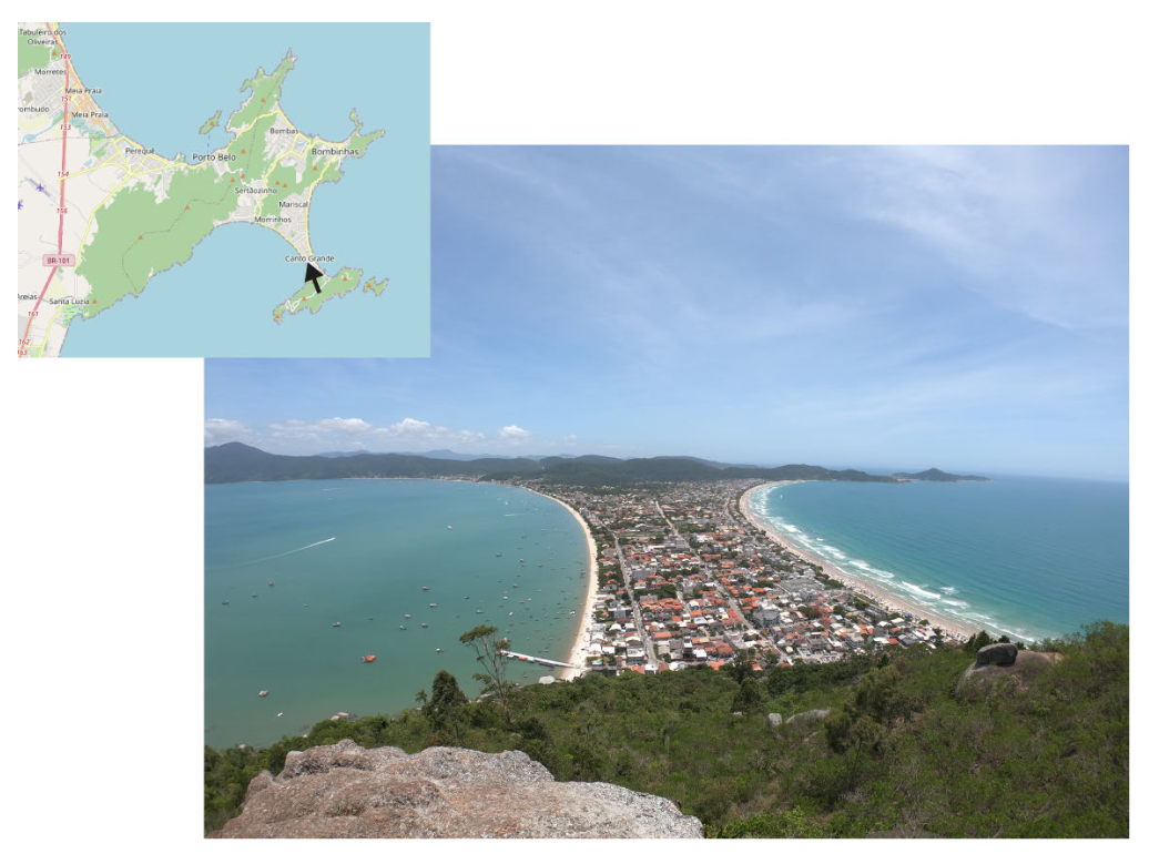
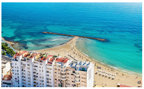
An obstacle in front of a coast such as a rock outcrop, an offshore breakwater, or even a shipwreck will reduce the wave activity in the zone of wave shadow between the object and the shore. Since the reduced wave activity in the shadow zone will result in a reduced sediment transport capacity, material being carried along the shore will be deposited in the shadow zone forming a tombolo. Initially only a shoal will form that we refer to as a salient. This can, however, develop into a point of land connecting the original shoreline to the obstacle (see Figs. 8.20 and 8.21). We now speak of tombolo. A tombolo completely blocks the longshore transport in the zone landward of the obstacle.
These shadow zone effects can be used to stimulate and preserve a recreational beach (Sect. 10.5.4). Have a look at Fig. 10.41, which shows salient and tombolo formation behind a series of emerged (i.e. having their crests above MSL) offshore breakwaters.
The development of a tombolo as explained above depends upon a transport of material parallel to the coast; the reasoning is that in the shadow zones behind obstacles, the breaking wave heights and thus longshore transport capacity is reduced and sediment is deposited. Note that due to diffraction of waves around the ends of the breakwater still some wave action will be present behind the breakwater (the wave heights at the end of the breakwater are in the order of magnitude of 50% of the original incoming wave height, see Sect. 5.2.4). Example 8.4.3.1 discusses the shoreline development resulting from an emerged breakwater (partly) blocking the longshore sediment transport by obliquely incident waves.
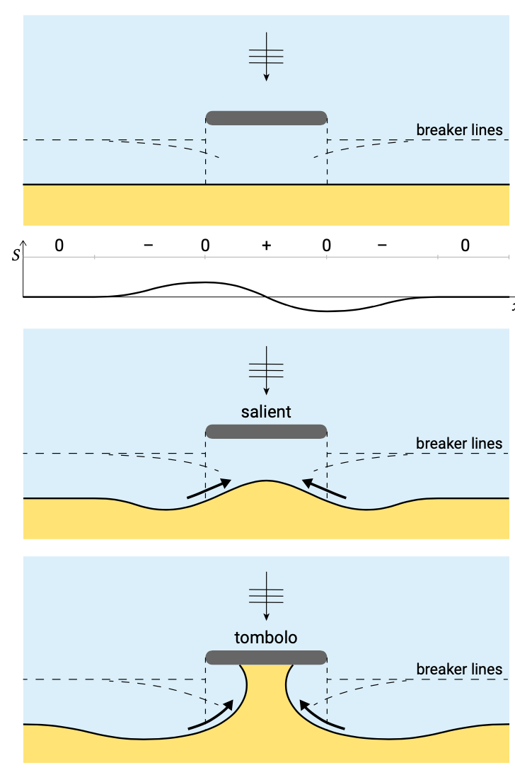
Besides the shoreline development, as a result of breaking wave height reduction in the shadow zone and subsequent gradients in longshore sediment transport (illustrated in Example 8.4.3.1), two subtler effects play a role, namely: 1) due to the changes in wave angles in the shadow zone; and 2) due to secondary current patterns as a result of set-up differences. These additional effects enhance the pattern of deposition behind the obstacle for obliquely incident waves and are the reason that even for normally incident waves a salient or tombolo can be formed (Fig. 8.23). This can be explained as follows. Due to diffraction into the shadow zone not only the wave heights, but also the wave angles are affected. Hence, even in the case of normally incident waves, the diffracted waves behind the breakwater approach the original coastline at some angle. This results in an initial sediment transport pattern with transports from both breakwater ends towards the shadow zone. Further, as shown in Fig. 5.46, nearshore currents run towards the shadow zone from both sides of an emerged obstacle. This secondary current pattern also enhances the transport towards the shadow zone.
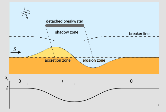
Consider an emerged detached breakwater along a coast with initially straight and parallel depth contours (Fig. 8.22). Waves are incident at an angle of \(15^{\circ}\). The natural surf zone width is smaller than the distance between the breakwater and the shore. The length of the breakwater is equal to its distance from the shore. As in Fig. 8.17, Fig. 8.22 qualitatively shows the sediment transport as a function of the distance alongshore, for the initially straight shoreline, estimated based on a hypothesised variation of the wave height behind the breakwater. Next, the areas where the expected shoreline response is accretive (negative transport gradients, sediment transport convergence, indicated with ‘+’) and erosive (positive transport gradients, sediment transport divergence, indicated with ‘−’) can be identified. Based on the initial sediment transport variations alongshore, sketch the expected shoreline development. The result is a wave-like initial pattern of updrift accretion (the shoreline bulges seaward) and downdrift erosion (the shoreline curves landward) as in Fig. 8.22.
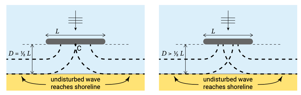
Figure 8.23 shows the resulting symmetrical shoreline development, for normally incident waves, with erosion on either side of the breakwater and accretion behind the structure. The initial shoreline development takes the form of a salient (lower panel), which may or may not develop over time into a tombolo (upper panel). A tombolo is more likely to develop if the breakwater is located in or just outside the surf zone (since the responsible currents are generated in the surf-zone) and if its length is relatively large. If the length is larger than, say, twice the distance from the coast, the diffracted wave heights reduce to zero in the centreline of the structure (Fig. 8.24, left figure). In that case the sediment stirring and transporting capacity behind the breakwater is not enough to keep a passage open. For a relatively short breakwater, the equilibrium shoreline will take the form of a salient (Fig. 8.24, right figure).
Also in the case of submerged obstacles, tombolos or salients may develop. However in those cases, any accretional tendency may be counteracted by a (possibly stronger) erosional effect. This is related to the wave-induced current pattern as shown in Fig. 5.49. The onshore directed wave forces, as a result of waves breaking on a shoal or submerged breakwater, result in a large on-shore flow of water. This is compensated for by rip currents returning seaward at either side of the shoal or breakwater. These currents can carry large amount of sediments from the shadow zone seaward and hence create large erosion. Some consequences for submerged breakwater design are discussed in Sect. 10.5.4.