10.5.4: Detached shore parallel offshore breakwaters
- Page ID
- 16436
\( \newcommand{\vecs}[1]{\overset { \scriptstyle \rightharpoonup} {\mathbf{#1}} } \)
\( \newcommand{\vecd}[1]{\overset{-\!-\!\rightharpoonup}{\vphantom{a}\smash {#1}}} \)
\( \newcommand{\id}{\mathrm{id}}\) \( \newcommand{\Span}{\mathrm{span}}\)
( \newcommand{\kernel}{\mathrm{null}\,}\) \( \newcommand{\range}{\mathrm{range}\,}\)
\( \newcommand{\RealPart}{\mathrm{Re}}\) \( \newcommand{\ImaginaryPart}{\mathrm{Im}}\)
\( \newcommand{\Argument}{\mathrm{Arg}}\) \( \newcommand{\norm}[1]{\| #1 \|}\)
\( \newcommand{\inner}[2]{\langle #1, #2 \rangle}\)
\( \newcommand{\Span}{\mathrm{span}}\)
\( \newcommand{\id}{\mathrm{id}}\)
\( \newcommand{\Span}{\mathrm{span}}\)
\( \newcommand{\kernel}{\mathrm{null}\,}\)
\( \newcommand{\range}{\mathrm{range}\,}\)
\( \newcommand{\RealPart}{\mathrm{Re}}\)
\( \newcommand{\ImaginaryPart}{\mathrm{Im}}\)
\( \newcommand{\Argument}{\mathrm{Arg}}\)
\( \newcommand{\norm}[1]{\| #1 \|}\)
\( \newcommand{\inner}[2]{\langle #1, #2 \rangle}\)
\( \newcommand{\Span}{\mathrm{span}}\) \( \newcommand{\AA}{\unicode[.8,0]{x212B}}\)
\( \newcommand{\vectorA}[1]{\vec{#1}} % arrow\)
\( \newcommand{\vectorAt}[1]{\vec{\text{#1}}} % arrow\)
\( \newcommand{\vectorB}[1]{\overset { \scriptstyle \rightharpoonup} {\mathbf{#1}} } \)
\( \newcommand{\vectorC}[1]{\textbf{#1}} \)
\( \newcommand{\vectorD}[1]{\overrightarrow{#1}} \)
\( \newcommand{\vectorDt}[1]{\overrightarrow{\text{#1}}} \)
\( \newcommand{\vectE}[1]{\overset{-\!-\!\rightharpoonup}{\vphantom{a}\smash{\mathbf {#1}}}} \)
\( \newcommand{\vecs}[1]{\overset { \scriptstyle \rightharpoonup} {\mathbf{#1}} } \)
\( \newcommand{\vecd}[1]{\overset{-\!-\!\rightharpoonup}{\vphantom{a}\smash {#1}}} \)
\(\newcommand{\avec}{\mathbf a}\) \(\newcommand{\bvec}{\mathbf b}\) \(\newcommand{\cvec}{\mathbf c}\) \(\newcommand{\dvec}{\mathbf d}\) \(\newcommand{\dtil}{\widetilde{\mathbf d}}\) \(\newcommand{\evec}{\mathbf e}\) \(\newcommand{\fvec}{\mathbf f}\) \(\newcommand{\nvec}{\mathbf n}\) \(\newcommand{\pvec}{\mathbf p}\) \(\newcommand{\qvec}{\mathbf q}\) \(\newcommand{\svec}{\mathbf s}\) \(\newcommand{\tvec}{\mathbf t}\) \(\newcommand{\uvec}{\mathbf u}\) \(\newcommand{\vvec}{\mathbf v}\) \(\newcommand{\wvec}{\mathbf w}\) \(\newcommand{\xvec}{\mathbf x}\) \(\newcommand{\yvec}{\mathbf y}\) \(\newcommand{\zvec}{\mathbf z}\) \(\newcommand{\rvec}{\mathbf r}\) \(\newcommand{\mvec}{\mathbf m}\) \(\newcommand{\zerovec}{\mathbf 0}\) \(\newcommand{\onevec}{\mathbf 1}\) \(\newcommand{\real}{\mathbb R}\) \(\newcommand{\twovec}[2]{\left[\begin{array}{r}#1 \\ #2 \end{array}\right]}\) \(\newcommand{\ctwovec}[2]{\left[\begin{array}{c}#1 \\ #2 \end{array}\right]}\) \(\newcommand{\threevec}[3]{\left[\begin{array}{r}#1 \\ #2 \\ #3 \end{array}\right]}\) \(\newcommand{\cthreevec}[3]{\left[\begin{array}{c}#1 \\ #2 \\ #3 \end{array}\right]}\) \(\newcommand{\fourvec}[4]{\left[\begin{array}{r}#1 \\ #2 \\ #3 \\ #4 \end{array}\right]}\) \(\newcommand{\cfourvec}[4]{\left[\begin{array}{c}#1 \\ #2 \\ #3 \\ #4 \end{array}\right]}\) \(\newcommand{\fivevec}[5]{\left[\begin{array}{r}#1 \\ #2 \\ #3 \\ #4 \\ #5 \\ \end{array}\right]}\) \(\newcommand{\cfivevec}[5]{\left[\begin{array}{c}#1 \\ #2 \\ #3 \\ #4 \\ #5 \\ \end{array}\right]}\) \(\newcommand{\mattwo}[4]{\left[\begin{array}{rr}#1 \amp #2 \\ #3 \amp #4 \\ \end{array}\right]}\) \(\newcommand{\laspan}[1]{\text{Span}\{#1\}}\) \(\newcommand{\bcal}{\cal B}\) \(\newcommand{\ccal}{\cal C}\) \(\newcommand{\scal}{\cal S}\) \(\newcommand{\wcal}{\cal W}\) \(\newcommand{\ecal}{\cal E}\) \(\newcommand{\coords}[2]{\left\{#1\right\}_{#2}}\) \(\newcommand{\gray}[1]{\color{gray}{#1}}\) \(\newcommand{\lgray}[1]{\color{lightgray}{#1}}\) \(\newcommand{\rank}{\operatorname{rank}}\) \(\newcommand{\row}{\text{Row}}\) \(\newcommand{\col}{\text{Col}}\) \(\renewcommand{\row}{\text{Row}}\) \(\newcommand{\nul}{\text{Nul}}\) \(\newcommand{\var}{\text{Var}}\) \(\newcommand{\corr}{\text{corr}}\) \(\newcommand{\len}[1]{\left|#1\right|}\) \(\newcommand{\bbar}{\overline{\bvec}}\) \(\newcommand{\bhat}{\widehat{\bvec}}\) \(\newcommand{\bperp}{\bvec^\perp}\) \(\newcommand{\xhat}{\widehat{\xvec}}\) \(\newcommand{\vhat}{\widehat{\vvec}}\) \(\newcommand{\uhat}{\widehat{\uvec}}\) \(\newcommand{\what}{\widehat{\wvec}}\) \(\newcommand{\Sighat}{\widehat{\Sigma}}\) \(\newcommand{\lt}{<}\) \(\newcommand{\gt}{>}\) \(\newcommand{\amp}{&}\) \(\definecolor{fillinmathshade}{gray}{0.9}\)

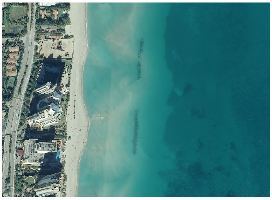
Detached breakwaters are breakwaters parallel to the coast at a certain distance from the coastline (‘detached’). They are often built from stone, just like ordinary harbour breakwaters or jetties and may be segmented (Fig. 10.17). Disadvantages are the relatively high construction and maintenance costs and the inconvenience/danger to swimmers and small boats. The breakwaters are either emerged (crest above MSL) or submerged (crest below MSL), see Fig. 10.16.

Emerged detached breakwaters with crest levels well above MSL are known to enhance accretion in their lee and have successfully been adopted for coastal protection for many decades. From an aesthetic point of view submerged breakwaters are preferred to surface-piercing structures (see Fig. 10.18). However, submerged breakwaters have resulted in enhanced shoreline erosion in a number of cases (Ranasinghe & Turner, 2006; Van Rijn, 2010). Below, we separately discuss the morphological impact of emerged and submerged breakwaters.
Emerged detached breakwaters
Most emerged breakwaters have been built along micro-tidal beaches in Japan, in the USA and along the Mediterranean. Few have been built along open, exposed meso-tidal and macro-tidal beaches. In the shadow zone behind the structures, tombolo development is stimulated. The governing mechanisms for this shoreline accretion were treated in Sect. 8.4.3.
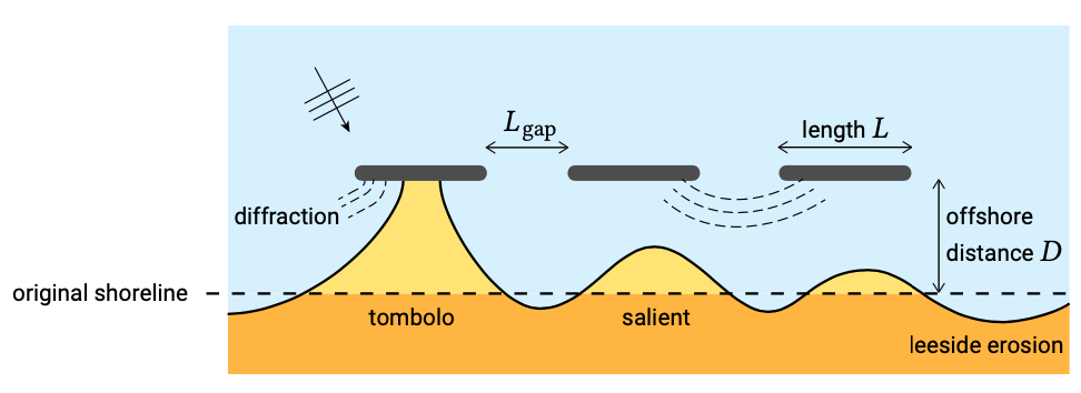
Since emerged breakwaters are effective in reducing the longshore sediment trans- port capacity in their shadow, structural coastal erosion can be solved with a series of emerged shore-parallel offshore breakwaters, as in Fig. 10.17. In the example of Fig. 10.7 the sediment transport in the cross-section through point B must be reduced from \(S_B\) to \(S_A\) (but not to zero, to avoid unnecessarily large lee-side erosion). Therefore, either in the area in the lee of an offshore breakwater near B or in the area seaward of that breakwater a non-zero sediment transport is required. A salient occurs for a not too large negative longshore transport gradient behind the breakwater, but still allows sediment to be transported via the shadow zone behind of the breakwater to downdrift beaches. A tombolo prevents this.

The type of beach planform that evolves strongly depends on dimensions and geometry (breakwater length \(L\), offshore distance to original shoreline \(D\) and length of gap between segments \(L_{\text{gap}}\), see Fig. 10.19). Bricio et al. (2008) have analysed 27 detached breakwater projects along the northeast Catalonian coastline (almost tideless) of Spain based on pre- and post-project aerial photographs. The offshore distances \(D\) are in the range of 80 m to 230 m and the (emerged) breakwater lengths \(L\) in the range of 60 m to 240 m. Tombolos were found for \(L/D > 1.3\) and salients for \(0.5 < L/D < 1.3\). These findings are broadly in line with other empirical relationships. In Sect. 8.4.3, we assumed tombolo formation for \(L/D > 2\) based on non-interfering diffraction patterns.
Opposite the gaps, shoreline erosion may occur if the gaps are sufficiently large (say \(L_{\text{gap}} / L > 1\) to 1.5).
From the above, it follows that the optimal emerged breakwaters in terms of coastal protection are built close to the shore with a high crest level and small gap lengths, but such a structure will largely block the horizon and is not attractive in terms of beach recreation.
Emerged breakwaters also reduce storm-induced beach and dune erosion to a certain extent. However, the still water level during a storm often increases (storm surge, see Sect. 5.6). Therefore, depending on the crest levels above MSL, tidal range and storm surge levels, large storm waves may still pass over the structure, such that storm erosion cannot be completely stopped.
Submerged detached breakwaters
Examples are known from field and laboratory tests in which severe erosion is generated landward of submerged breakwaters. E.g. in Dean et al. (1997) a striking example is described where the application of offshore breakwaters yields more erosion than without this ‘protection’ measure: a single submerged breakwater built on the lower east coast of Florida (USA), approximately 7 km south of the entrance of the Port of Palm Beach was later (1995) removed because of excessive erosion problems in the lee of the breakwater.
A submerged breakwater parallel to and at some distance from the shoreline will undoubtedly reduce the wave heights landward of the submerged breakwater (depending on the wave climate, the positioning and the crest height relative to the still water level). As for emerged structures, this may result in accretion behind the structure. However, wave breaking on the structure drives a current pattern with diverging shore-parallel currents in the shadow zone of the breakwater (see Sects. 5.5.7 and 8.4.3). Along the end sections of (segmented) breakwaters, the currents escape in the seaward direction (see Fig. 5.49). This current pattern can transport a lot of sediment outside the area and counteract the accretional tendency. The erosional current pattern becomes stronger for decreasing distance between the breakwater and the shore. Hence, shoreline erosion may occur, for instance, if a submerged breakwater is built too close to the shore.
Unfortunately very few guidelines are available for submerged breakwater design, as yet. Clearly, the successful application of submerged breakwater requires a better understanding of the shoreline response. Any attempt to understand and model the morphodynamic impact of (submerged) structures requires the explicit consideration of the complicated circulation currents.
Submerged structures have only a limited effect on storm-induced erosion, as most of the storm waves can be expected to pass over the structure and attack the dune or cliff front. Supplementary beach nourishments may be required to deal with local storm-induced shoreline erosion, especially opposite to gaps, where under storm conditions large amounts of sediment may irrevocably be carried seaward.
Sometimes, submerged breakwaters are constructed as sills between the tip of groynes to support the seaward toe of beach fills (perched beaches, see Fig. 10.39).
In conclusion, in this paragraph the morphological consequences of detached shore parallel offshore breakwater were discussed. The fine-tuning of series of offshore breakwaters is a very difficult task, especially for submerged breakwaters. Waves from different directions and tidal effects (water level and currents) also seriously complicate the situation. A successful project may involve an initial design phase based on mathematical and physical modelling, the testing of the design by means of a field pilot project including a detailed monitoring programme and the fine-tuning of the design by modification of breakwater lengths based on the field experiences.
If a submerged or low-crested emerged breakwater is not designed properly, additional negative morphological effects such as local scour and shoreline erosion may easily occur. Attention should further be paid to mitigation of downdrift (leeside) erosion. This can be established by creating a transitional zone with gradually increasing gap lengths and/or decreasing crest levels. In addition, protection measures may be required against local toe scour in front of the breakwater, just as for seawalls (see Sect. 10.6.2).


