

4: Climate Change - The Carbon Cycle and Carbon Chemistry
- Page ID
- 34459
\( \newcommand{\vecs}[1]{\overset { \scriptstyle \rightharpoonup} {\mathbf{#1}} } \)
\( \newcommand{\vecd}[1]{\overset{-\!-\!\rightharpoonup}{\vphantom{a}\smash {#1}}} \)
\( \newcommand{\dsum}{\displaystyle\sum\limits} \)
\( \newcommand{\dint}{\displaystyle\int\limits} \)
\( \newcommand{\dlim}{\displaystyle\lim\limits} \)
\( \newcommand{\id}{\mathrm{id}}\) \( \newcommand{\Span}{\mathrm{span}}\)
( \newcommand{\kernel}{\mathrm{null}\,}\) \( \newcommand{\range}{\mathrm{range}\,}\)
\( \newcommand{\RealPart}{\mathrm{Re}}\) \( \newcommand{\ImaginaryPart}{\mathrm{Im}}\)
\( \newcommand{\Argument}{\mathrm{Arg}}\) \( \newcommand{\norm}[1]{\| #1 \|}\)
\( \newcommand{\inner}[2]{\langle #1, #2 \rangle}\)
\( \newcommand{\Span}{\mathrm{span}}\)
\( \newcommand{\id}{\mathrm{id}}\)
\( \newcommand{\Span}{\mathrm{span}}\)
\( \newcommand{\kernel}{\mathrm{null}\,}\)
\( \newcommand{\range}{\mathrm{range}\,}\)
\( \newcommand{\RealPart}{\mathrm{Re}}\)
\( \newcommand{\ImaginaryPart}{\mathrm{Im}}\)
\( \newcommand{\Argument}{\mathrm{Arg}}\)
\( \newcommand{\norm}[1]{\| #1 \|}\)
\( \newcommand{\inner}[2]{\langle #1, #2 \rangle}\)
\( \newcommand{\Span}{\mathrm{span}}\) \( \newcommand{\AA}{\unicode[.8,0]{x212B}}\)
\( \newcommand{\vectorA}[1]{\vec{#1}} % arrow\)
\( \newcommand{\vectorAt}[1]{\vec{\text{#1}}} % arrow\)
\( \newcommand{\vectorB}[1]{\overset { \scriptstyle \rightharpoonup} {\mathbf{#1}} } \)
\( \newcommand{\vectorC}[1]{\textbf{#1}} \)
\( \newcommand{\vectorD}[1]{\overrightarrow{#1}} \)
\( \newcommand{\vectorDt}[1]{\overrightarrow{\text{#1}}} \)
\( \newcommand{\vectE}[1]{\overset{-\!-\!\rightharpoonup}{\vphantom{a}\smash{\mathbf {#1}}}} \)
\( \newcommand{\vecs}[1]{\overset { \scriptstyle \rightharpoonup} {\mathbf{#1}} } \)
\(\newcommand{\longvect}{\overrightarrow}\)
\( \newcommand{\vecd}[1]{\overset{-\!-\!\rightharpoonup}{\vphantom{a}\smash {#1}}} \)
\(\newcommand{\avec}{\mathbf a}\) \(\newcommand{\bvec}{\mathbf b}\) \(\newcommand{\cvec}{\mathbf c}\) \(\newcommand{\dvec}{\mathbf d}\) \(\newcommand{\dtil}{\widetilde{\mathbf d}}\) \(\newcommand{\evec}{\mathbf e}\) \(\newcommand{\fvec}{\mathbf f}\) \(\newcommand{\nvec}{\mathbf n}\) \(\newcommand{\pvec}{\mathbf p}\) \(\newcommand{\qvec}{\mathbf q}\) \(\newcommand{\svec}{\mathbf s}\) \(\newcommand{\tvec}{\mathbf t}\) \(\newcommand{\uvec}{\mathbf u}\) \(\newcommand{\vvec}{\mathbf v}\) \(\newcommand{\wvec}{\mathbf w}\) \(\newcommand{\xvec}{\mathbf x}\) \(\newcommand{\yvec}{\mathbf y}\) \(\newcommand{\zvec}{\mathbf z}\) \(\newcommand{\rvec}{\mathbf r}\) \(\newcommand{\mvec}{\mathbf m}\) \(\newcommand{\zerovec}{\mathbf 0}\) \(\newcommand{\onevec}{\mathbf 1}\) \(\newcommand{\real}{\mathbb R}\) \(\newcommand{\twovec}[2]{\left[\begin{array}{r}#1 \\ #2 \end{array}\right]}\) \(\newcommand{\ctwovec}[2]{\left[\begin{array}{c}#1 \\ #2 \end{array}\right]}\) \(\newcommand{\threevec}[3]{\left[\begin{array}{r}#1 \\ #2 \\ #3 \end{array}\right]}\) \(\newcommand{\cthreevec}[3]{\left[\begin{array}{c}#1 \\ #2 \\ #3 \end{array}\right]}\) \(\newcommand{\fourvec}[4]{\left[\begin{array}{r}#1 \\ #2 \\ #3 \\ #4 \end{array}\right]}\) \(\newcommand{\cfourvec}[4]{\left[\begin{array}{c}#1 \\ #2 \\ #3 \\ #4 \end{array}\right]}\) \(\newcommand{\fivevec}[5]{\left[\begin{array}{r}#1 \\ #2 \\ #3 \\ #4 \\ #5 \\ \end{array}\right]}\) \(\newcommand{\cfivevec}[5]{\left[\begin{array}{c}#1 \\ #2 \\ #3 \\ #4 \\ #5 \\ \end{array}\right]}\) \(\newcommand{\mattwo}[4]{\left[\begin{array}{rr}#1 \amp #2 \\ #3 \amp #4 \\ \end{array}\right]}\) \(\newcommand{\laspan}[1]{\text{Span}\{#1\}}\) \(\newcommand{\bcal}{\cal B}\) \(\newcommand{\ccal}{\cal C}\) \(\newcommand{\scal}{\cal S}\) \(\newcommand{\wcal}{\cal W}\) \(\newcommand{\ecal}{\cal E}\) \(\newcommand{\coords}[2]{\left\{#1\right\}_{#2}}\) \(\newcommand{\gray}[1]{\color{gray}{#1}}\) \(\newcommand{\lgray}[1]{\color{lightgray}{#1}}\) \(\newcommand{\rank}{\operatorname{rank}}\) \(\newcommand{\row}{\text{Row}}\) \(\newcommand{\col}{\text{Col}}\) \(\renewcommand{\row}{\text{Row}}\) \(\newcommand{\nul}{\text{Nul}}\) \(\newcommand{\var}{\text{Var}}\) \(\newcommand{\corr}{\text{corr}}\) \(\newcommand{\len}[1]{\left|#1\right|}\) \(\newcommand{\bbar}{\overline{\bvec}}\) \(\newcommand{\bhat}{\widehat{\bvec}}\) \(\newcommand{\bperp}{\bvec^\perp}\) \(\newcommand{\xhat}{\widehat{\xvec}}\) \(\newcommand{\vhat}{\widehat{\vvec}}\) \(\newcommand{\uhat}{\widehat{\uvec}}\) \(\newcommand{\what}{\widehat{\wvec}}\) \(\newcommand{\Sighat}{\widehat{\Sigma}}\) \(\newcommand{\lt}{<}\) \(\newcommand{\gt}{>}\) \(\newcommand{\amp}{&}\) \(\definecolor{fillinmathshade}{gray}{0.9}\)Search Fundamentals of Biochemistry
(Learning goals written by Claude, Anthropic)
By the end of this chapter, students should be able to:
Stocks, Fluxes, and Mass Balance in the Carbon Cycle
- Define carbon stocks (GtC) and fluxes (GtC/yr), perform dimensional analysis to interconvert GtC, Gt CO₂, and ppm, and apply the Law of Mass Conservation to the global carbon budget to show that anthropogenic fossil fuel emissions (+9.6 GtC/yr) are now the single largest flux in the carbon cycle.
- Interpret carbon budget diagrams showing EFOS, ELUC, SLAND, SOCEAN, and GATM, explain why the cumulative +275 GtC from fossil fuel emissions since 1850 translates to a ~129 ppm rise in atmospheric CO₂, and use Le Châtelier's Principle to predict how decreasing atmospheric CO₂ would affect oceanic uptake rates.
- Describe how simple Vcell-based carbon cycle models are constructed from stock reserves and apparent rate constants (J = kapp[stock]), explain what assumptions simplify such models, and interpret why their outputs closely match IPCC SSP1-2.6 projections despite those simplifications.
- Explain the ExxonMobil disinformation case: describe what their internal models accurately predicted, what their executives publicly claimed, and why this is a defining example of deliberate scientific misinformation with global consequences.
Ocean Carbon Chemistry and δ¹³C as a Climate Proxy
- Write the coupled equilibrium reactions linking atmospheric CO₂ to dissolved CO₂, carbonic acid, bicarbonate, and carbonate in the ocean, explain how these reactions buffer ocean pH, and describe how rock weathering and ocean uptake regulate long-term atmospheric CO₂.
- Explain the kinetic isotope effect for ¹³C — why its lower zero-point energy raises the activation energy for bond formation/cleavage — and use this to predict why RuBisCO discriminates against ¹³CO₂, why plants and organic matter have more negative δ¹³C values than atmospheric CO₂, and why C3 plants (δ¹³C ≈ −25 to −30‰) differ from C4 plants (δ¹³C ≈ −10 to −15‰).
- Interpret positive and negative δ¹³C excursions in ocean sediment carbonate records — explaining how high primary productivity and organic carbon burial produce positive excursions while mass extinctions and massive carbon injection produce negative ones — and apply this framework to the Lomagundi-Jatuli event, the PETM, the Permian-Triassic boundary, and the K-Pg boundary.
- Use δ¹³C data from ice cores to explain two specific historical events: the ~7–10 ppm CO₂ drop and positive δ¹³C excursion in 1500–1650 CE following the Great Dying of Indigenous peoples (reforestation of ~56 million hectares), and the decreasing δ¹³C since the Industrial Revolution as definitive evidence that rising CO₂ is from biogenic fossil fuel combustion.
The Methane Cycle and •OH as Atmospheric Scrubber
- Describe the global methane budget — identifying major sources (wetlands, agriculture, fossil fuels, landfills) and their characteristic δ¹³CCH₄ values — and explain how δ¹³C isotope source attribution showed that ~85% of post-2007 methane growth came from microbial rather than fossil fuel sources, representing a dangerous positive climate feedback.
- Explain the photochemical production of •OH from ozone photolysis and water vapor, write the rate-limiting H-abstraction reaction that initiates CH₄ oxidation (CH₄ + •OH → •CH₃ + H₂O), explain why this gives atmospheric methane a half-life of 9–10 years, and connect •OH depletion to extended methane atmospheric lifetime as an additional positive warming feedback.
The Carbon Cycle
In the last chapter section, we used oxygen isotopes in ice and ocean sediment cores going back millions of years to address the history and mechanisms of climate change. We focused on 18O/16O ratios in H2O and calcite (CaCO3) shells and on the corresponding δ18O values in ice and sediment cores to determine CO2 and temperature over climatic history. Now it's time to talk about the other key atom, C, the ratio of 13C/12C and corresponding δ13C values, not only in CaCO3 but also in CO2 and the organic molecules it transforms into through photosynthesis and the heterotrophic organisms that consume them. 13C partitions not only into inorganic carbon but also into organic molecules throughout life. Hence, we need a more detailed understanding of the carbon cycle.
The carbon cycle is likely discussed in introductory chapters in biology textbooks, but probably never in chemistry texts. It is fundamental to understanding climate, its control and change, and human processes that alter it. Figure \(\PageIndex{1}\) shows one representation of the carbon cycle. Calculated amounts of carbon found in the lithosphere (the solid part of the Earth), the atmosphere (specifically the lower part, the troposphere), and the hydrosphere are shown. (The cryosphere, the ice found in Greenland and Antarctica, is not shown. The biosphere includes part of these "spheres" that harbor life. Since life has been found 10 km down in the crust, we'll refer to the entire region shown in the diagrams as the biosphere. Alternatively, carbon can be found in four key reservoirs: atmospheric, terrestrial, oceanic, and buried sediments
Figure \(\PageIndex{1}\) presents carbon stores in petagrams (1015 g) or gigatons of carbon (GtC), where 1 petagram equals 1 billion metric tons (approximately 1.1 billion US tons).
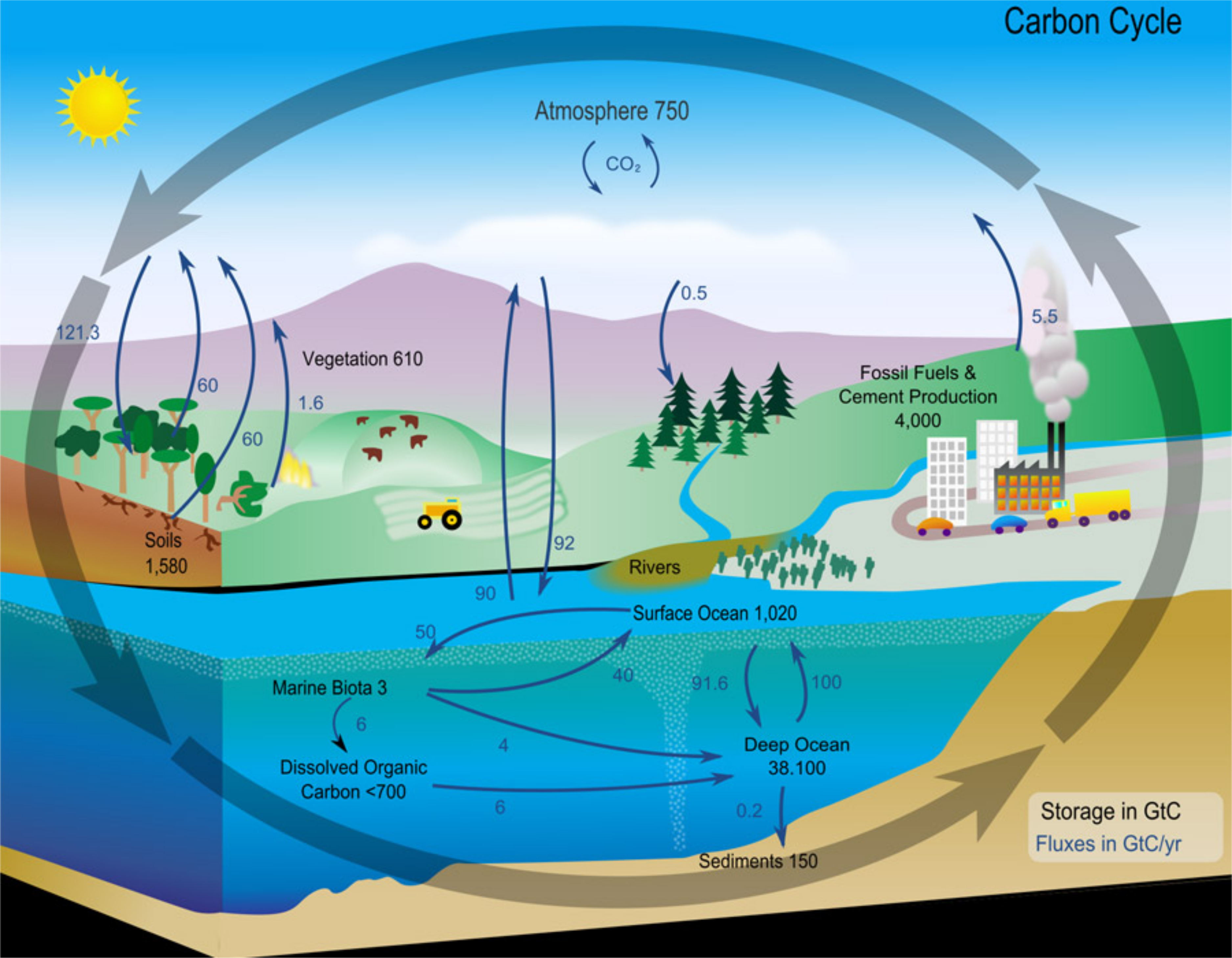
Figure \(\PageIndex{1}\): The carbon cycle. https://commons.wikimedia.org/wiki/F...te_diagram.svg
In addition to the total amount of carbon stored in each region (GtC), the net changes in carbon per year as it moves into and out of reserves (GtC/yr) are shown in blue arrows with attached numbers.
Carbon exchanges in the cycle occur at different time scales. Geologically, "fast" exchange, on a time scale of up to 1000s of years, occurs among the oceans, atmosphere, and land. In contrast, a slow exchange (over hundreds of thousands to millions of years) occurs in deep soils, deep ocean sediments, and rocks. We will mostly consider exchanges among the atmosphere, land, and oceans.
CO2 in the terrestrial biosphere is removed by photosynthesis and returned by respiration by autotrophs like plants and heterotrophs like microbes that consume soil carbon and plant remains. CO2 in the atmosphere is also removed by ocean autotrophs, such as ocean phytoplankton, and by partitioning into dissolved inorganic carbon (DIC) species such as HCO3- and CO32-.
Before we probe some relevant reactions within the carbon cycle and analyze them quantitatively, let's get a visual impression of how CO2 flows into and through the atmosphere (in 2020) with this stunning, high-resolution video model from NASA. Listen to the narration to visualize the sources of significant emissions (power plants, forest fires) and the changes in emissions driven by human activity across day/night cycles.
Now let's look at the factors driving our rising CO2 levels and global warming. To do that, we must put numbers on the cycle to quantify it.
Quantifying the carbon cycle
In Chapter 31.1, we used parts per million (ppm) to express the amount of CO2 in the atmosphere. Table \(\PageIndex{1}\) below shows how to translate the percentage (parts per 100) for each component gas in the atmosphere (with which you are familiar) into ppm.
| Gas | % (parts per 100) in atm | parts per million |
|---|---|---|
| N2 | 78.09 | 780,900 |
| O2 | 20.94 | 209,400 |
| Ar | 0.93 | 9300 |
| CO2 | 0.0415 | 415 |
Table \(\PageIndex{1}\): Unit conversion - % to ppm
Climate scientists use ppm instead of concentration (in molecules/m3) because they want to know the relative percent increase over time, which is independent of temperature or pressure. In contrast, concentration depends on T and P, as you will remember from the ideal gas law, PV=nRT or n/V=P/RT, which you studied in introductory chemistry.
It is important to use dimensional analysis to interconvert units as well. Table \(\PageIndex{2}\) below shows conversion factors to switch between GtC, Gt CO2, and ppm.
| Convert from | to | conversion factor |
|---|---|---|
| GtC (Gigatons of carbon) | ppm CO2 | divide by 2.124 |
| GtC (Gigatons of carbon) | PgC (Petgrams of carbon) | multiply by 1 |
| Gt CO2 (Gigatons of carbon) | GtC (Gigatons of C) | divide by 3.664 = 44.01/12.01) |
| GtC (Gigatons of carbon) | MtC | multiply by 10000 |
Table \(\PageIndex{2}\): Unit conversion - GtC and Gt CO2
To be more technical, atmospheric CO2 concentrations are expressed as the mol fraction of CO2 in dry air. The ppm for CO2 is μmol CO2 per mole of dry air.
We need to assign numbers to the components of the carbon cycle to analyze them quantitatively. Otherwise, we can't know what is happening, nor can we predict the future with any certainty. For many, stoichiometry and reaction kinetics are probably the least-liked parts of chemistry, but they are critical for understanding climate change. We have to apply them globally. Two key terms are important:
Stocks or reserves: How much carbon (mass in Gigatons or petagrams) is stored in given locations in the biosphere? This allows us to understand, for example, what % of all carbon stocks are in the ocean. Stocks are usually reported in gigatons of carbon (GtC), not carbon dioxide, because many stocks (such as fossil fuels) consist mostly of C and H, not oxygen. As in stoichiometry calculations in introductory chemistry courses, GtC in the atmosphere can be converted to gigatons of CO2 using dimensional analysis.
Fluxes (rates): How much carbon is transferred from one reserve to another per year (Gigatons/yr). Climate scientists apply the Law of Mass Conservation, which you learned in introductory chemistry, to the biosphere.
Figure \(\PageIndex{2}\) shows the reserves/stock (GtC) for reserves and decadal (2012-2021) average fluxes (large and small arrows, GtC/yr) for individual or aggregated stocks.
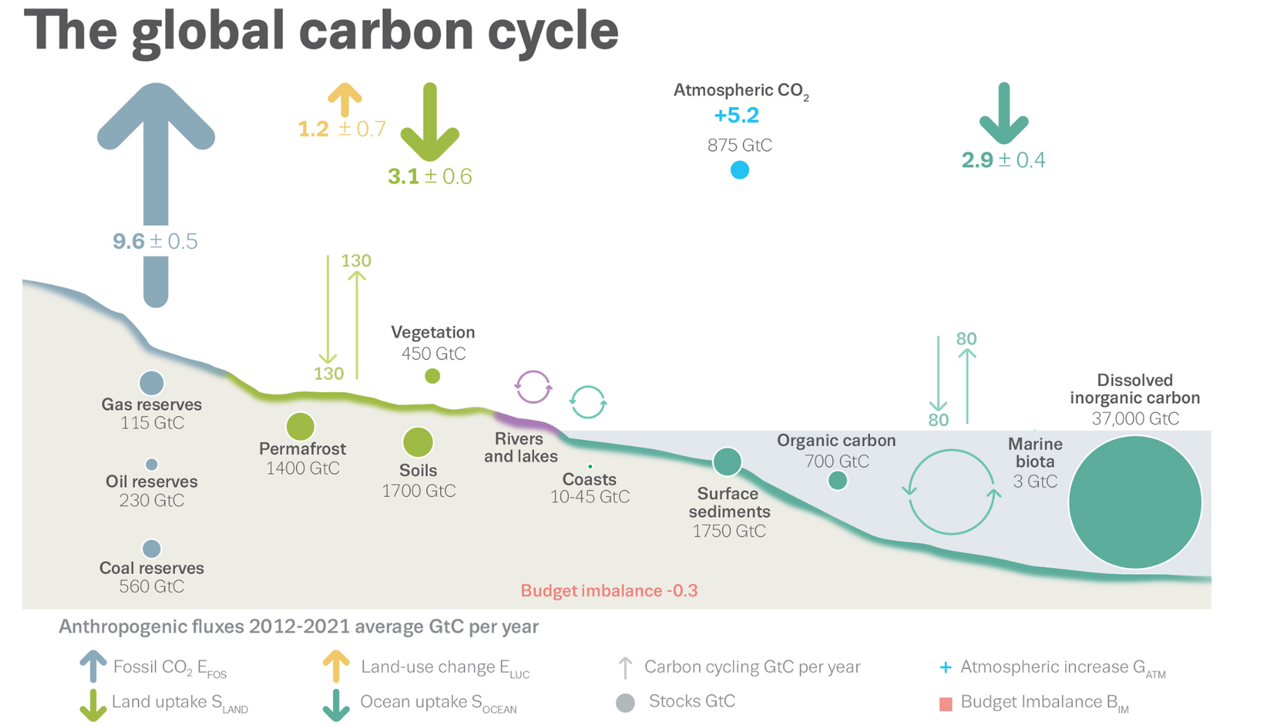
Figure \(\PageIndex{2}\): Schematic representation of the overall perturbation of the global carbon cycle caused by anthropogenic activities averaged globally for the decade 2012–2021. E represents emission and S "sink". Earth Syst. Sci. Data, 14, 4811–4900, 2022. https://doi.org/10.5194/essd-14-4811-2022. © Author(s) 2022. This work is distributed under the Creative Commons Attribution 4.0 License.
The abbreviations used are EFOS (emissions, fossil fuels), ELUC (emissions land use changes - principally deforestation), SLAND (terrestrial CO2 sink), SOCEAN (ocean CO2 sink), GATM (Growth Rate CO2 atm), BIM (carbon budget imbalance). Uncertainties are also shown, except for the atmospheric CO2 growth rate, which is known precisely through modern measurements. (It's also the easiest to measure). Human-caused (anthropogenic) changes occur on top of the carbon cycle.
The upward arrows indicate release into the atmosphere, and the downward arrows indicate absorption in the oceans and land. The thickness of the arrows gives a relative measure of the size of the emission or absorption. The thickest arrow and highest value (9.6 GtC/yr) is for the anthropogenic emission of carbon from our use of fossil fuels. Think about that! Humans are presently the most significant contributors to the carbon cycle. Before the Industrial Revolution, human contributions were minimal.
Figure 2 above shows that, on average, 9.6 GtC/yr was released from fossil fuel use between 2012 and 2021. The actual flux of anthropogenic carbon released in 2021 was 9.9 GtC, equivalent to 36.4 Gt CO2.
If you add the up arrows and subtract the down ones from that sum, you get +4.8 GtC/yr. This represents the net average increase in GtC in atmospheric CO2 per year for 2012-2021. That is close to the accurately and precisely known value of +5.2 GtC/yr increase from the CO2 we pour into the atmosphere from burning fossil fuels. Hence, the figure above is unbalanced (about 0.3 GtC too low - the BIM carbon budget imbalance). Still, given the difficulty in calculating these values, it is remarkably close to "mass balance," as you learned in introductory chemistry classes. In general, before the Industrial Revolution, the sum of the fluxes that added CO2 to the atmosphere was equal to the sum of the fluxes that removed it. That is, the system was in a steady state. That is no longer the case.
Figure \(\PageIndex{3}\) shows a breakdown of the factors contributing to annual (left) and cumulative (right) fluxes of carbon (GtC/yr), a metric for CO2 flux, over time since 1850.
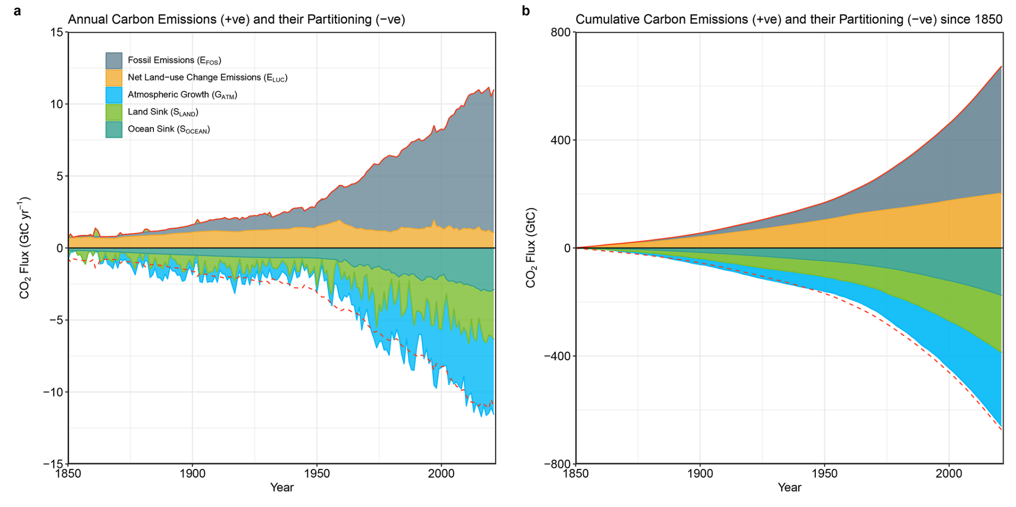
Figure \(\PageIndex{3}\): Combined components of the global carbon budget as a function of time for fossil CO2 emissions (EFOS, including a small sink from cement carbonation; grey) and emissions from land-use change (ELUC; brown), as well as their partitioning among the atmosphere (GATM; cyan), ocean (SOCEAN; blue), and land (SLAND; green). Panel (a) shows annual estimates of each flux ( GtC yr−1, and panel (b) shows the cumulative flux (the sum of all prior annual fluxes) since the year 1850. Again, the graph shows GtC not Gt CO2. . © Author(s), ibid
You might ask why the atmospheric growth in CO2 (shown in green) is negative. We'll answer that question below.
Lastly, let's consider the cumulative changes in GtC released and absorbed since 1850 (before the US Civil War and before the large CO2 release in modern times). Those data are shown in a bar graph in panel A of Figure \(\PageIndex{4}\). The bar graph in the right panel shows the mean decadal averages shown in Figure 2 above.
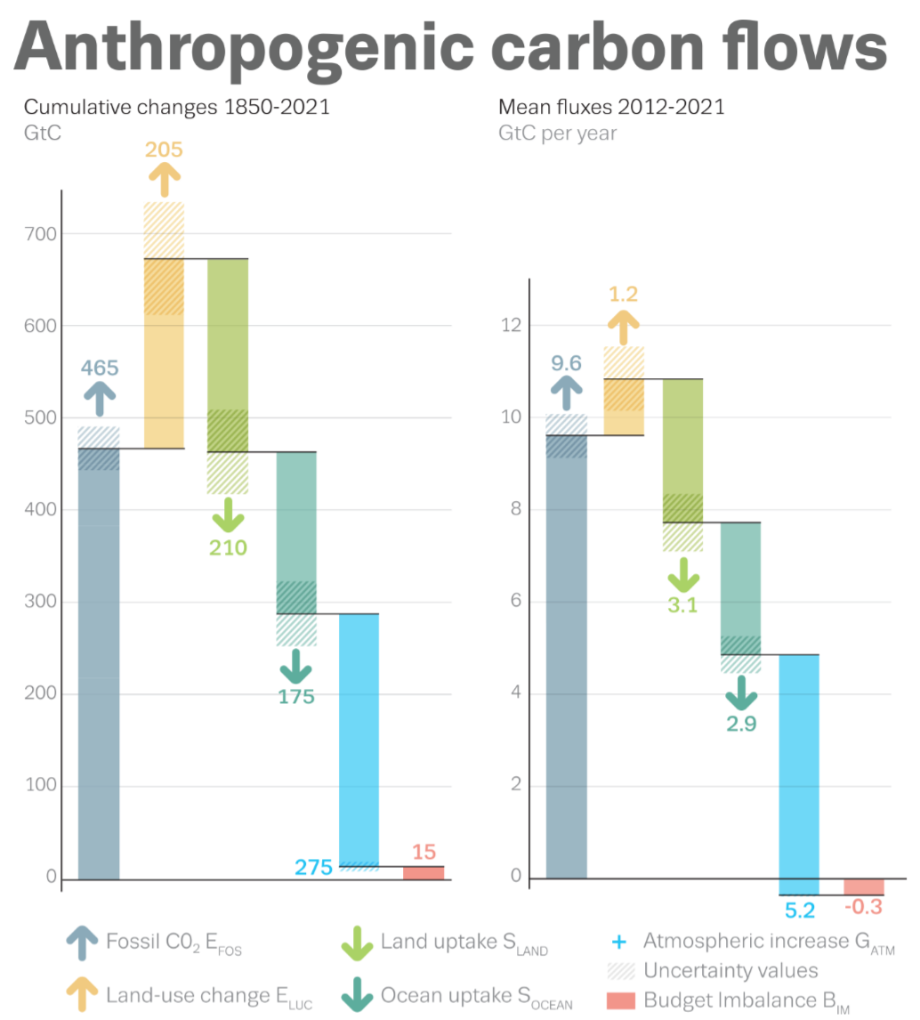
Figure \(\PageIndex{4}\): Total cumulative changes in GtC released and absorbed since 1850 (panel A) and mean decadal fluxes (panel B). EFOS (emissions, fossil fuels), ELUC (emissions land use changes - mostly deforestation), SLAND (terrestrial CO2 sink), SOCEAN (ocean CO2 sink), GATM (Growth Rate CO2 atm), BIM (carbon budget imbalance). © Author(s), ibid
The positive emission and negative absorption contributions are easily seen in the bar graph. The blue bar represents the net carbon emission from fossil fuels and fills the gap to complete the mass balance, as discussed above. It also explains the negative blue region in Figure 3. Keep in mind that the blue net flux from fossil fuels is positive.
The cumulative contributions from fossil fuel emissions required to close the gap and fulfill mass balance are +275 GtC, which, when multiplied by the conversion factor (1ppm/2.124 GtC), translates into a 129.5 ppm increase in atmospheric CO2 over that time. This is very close to independent measurements of a rise of 129.3 ppm (14.7-284.7) over that time.
The data from Figure \(\PageIndex{4}\) has been entered in the first four columns of Table \(\PageIndex{3}\) below.
| Source | Subtype | Stock reserves (GtC) |
J (Fluxes) GtC/yr + emission |
J=kapp[stock] |
|---|---|---|---|---|
| Atmosphere | - | 875 | ||
| Buried Fossil Fuels | Coal | 560 | +9.6 |
J=+9.6=k[905] (905 is the sum of stocks) k=0.0106 |
| Oil | 230 | |||
| Gas | 115 | |||
| Terrestrial | Permafrost | 1,400 |
+1.2 (Land use Δ) |
Juse=+1.2=kuse[3550]; kuse=0.000338 |
| Soil | 1,700 | |||
| Vegetation | 450 | |||
| Oceans | Coasts | 10-45 | -2.9 |
J=-2.9=k[875] |
| Ocean Surface Sediments | 1,750 | |||
| Organic carbon | 700 | |||
| Marine Biota | 3 | |||
| Dissolve Inorganic Carbon (DIC) | 37,000 |
We can use this data to develop a crude computational model predicting future CO2 emissions using Vcell, the program we used to produce time-course (concentration vs time) graphs for both simple and coupled signal transduction reaction pathways.
Vcell can be used to calculate fluxes (J) in reaction pathways, where J is the change in concentration of a species with time, given the initial concentration or amount of a reactant and the rate constants affecting its production or removal. If we use the amount of carbon (GtC) in each reservoir in the biosphere and crust as a relative measure of "concentration" and the known fluxes (GtC/yr) for the transfer of carbon to and from the atmosphere as given in Table 3, we could calculate an "apparent rate constant for each flux using this equation:
Jstock = kapp[stock] (where stock is given in GtC).
\begin{equation}
\mathrm{J}_{\text {stock }}=\mathrm{k}_{\mathrm{app}}[\text { stock in } \mathrm{GtC}]
\end{equation}
These "apparent" rate constants are needed to run the Vcell simulation that can reproduce the actual fluxes shown in Figures 2 and 4. The simulation can be run over time
A simple four-term model based on Figures 2 and 4 is shown below. Run the simulation and see how atmospheric CO2 changes with time. This model is offered only to show how climate models are made and used. The graphs are valid and sound given the input parameters, but the outputs are based on many assumptions that greatly simplify the model. For example, it assumes no new fossil fuel input from new drilling or mining.

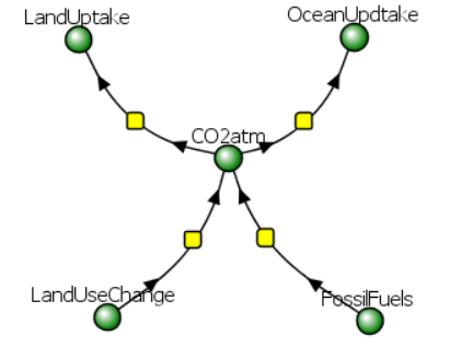
Alter the sliders on the model to change the rates of removal of CO2 atm through land uptake and ocean uptake. Also, change the rate of CO2 input from land use changes and burning fossil fuels. Try to "flatten" the curve earlier and to decrease CO2 atm faster.
You can also download the spreadsheet and plot the individual contributions to CO2 atm.
This simulation shows CO2 atm levels peaking at about 982 GtC in 51 years (2073), from its average decadal (2011-2021) value of 875. That is an increase of 107 GtC from now (50 ppm CO2 rise from the present 414 to 463 ppm). Over 50 years, this gives an average annual rise of 2.14 GtC/yr or about 1 ppm CO2/yr. A comparison of the predicted atmospheric CO2 (ppm) levels through 2100 for the IPCC SSP1-2.6 scenario (blue) and simple Vcell model (red) is shown in Figure \(\PageIndex{5}\).
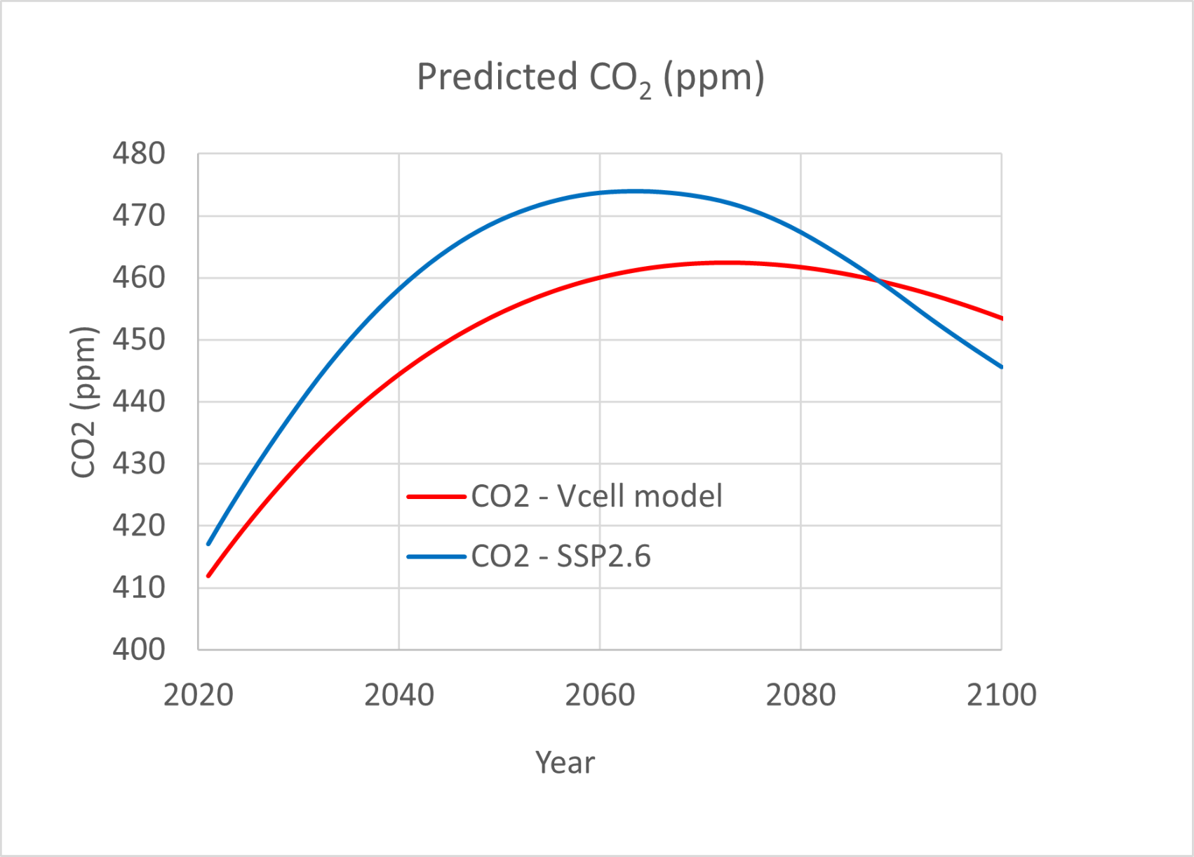
Figure \(\PageIndex{5}\): Predicted atmospheric CO2 (ppm) for SSP1-2.6 scenario (blue) and simple Vcell model (red)
SSP1-2.6 data - History: Meinshausen et al. GMD 2017 (https://doi.org/10.5194/gmd-10-2057-2017); Future: Meinshausen et al., GMD, 2020 (https://doi.org/10.5194/gmd-2019-222). https://climateanalytics.org/media/g...-3571-2020.pdf. https://gmd.copernicus.org/articles/13/3571/2020/
However imperfect the Vcell model is (incorrect assumptions, lack of complexity and feedback mechanisms, etc), the results shown above are very close to the projected increases in carbon dioxide in ppm described in IPCC reports for the SSP1-2.6 socioeconomic pathways, shown in the right panel (dark blue line) of Figure \(\PageIndex{6}\). This pathway predicts a rise of approximately 1.80 C in average global temperatures.
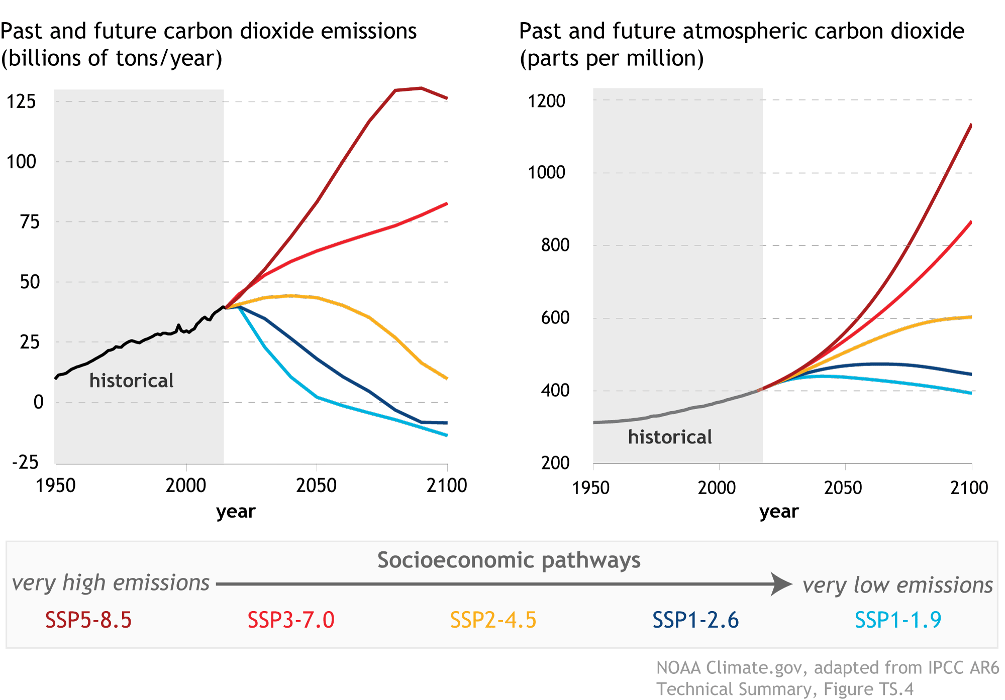
Figure \(\PageIndex{6}\): IPCC, 2021: Summary for Policymakers. In: Climate Change 2021: The Physical Science Basis. Contribution of Working Group I
to the Sixth Assessment Report of the Intergovernmental Panel on Climate Change [Masson-Delmotte, V., P. Zhai, A. Pirani, S.L.
Connors, C. Péan, S. Berger, N. Caud, Y. Chen, L. Goldfarb, M.I. Gomis, M. Huang, K. Leitzell, E. Lonnoy, J.B.R. Matthews, T.K.
Maycock, T. Waterfield, O. Yelekçi, R. Yu, and B. Zhou (eds.)].
Again, remember that the model is based on a ten-year average of CO2 emissions. Think of all the other assumptions in this model (other than the stock reserves and fluxes) that would give higher or lower values of future CO2 levels. One major one is that flux values are all held constant to allow calculations of the apparent rate constants for Vcell use. The model depletes much of the fossil fuel reserves. In addition, CO2 emissions in 2021 were 9.9 GtC/yr and are going up!
In addition, a change in one parameter can affect the others. For example, the net uptake of atmospheric CO2 by the land and oceans increased from 1960 to 2010, which makes sense given that higher atmospheric CO2 levels are forcing greater uptake (think Le Châtelier's Principle). Since the Industrial Revolution, the oceans have absorbed nearly 40% of the CO2 emitted by burning fossil fuels. If the uptake rate decreases (i.e., if we start to saturate oceanic uptake), CO2 accumulation in the atmosphere will accelerate. Data also suggest that if we successfully decrease CO2 in the atmosphere, the oceans would respond by decreasing their uptake, slowing the rate of temperature reduction.
An interesting example relating atmospheric and ocean CO2 occurred from 1990 to 2000, when it was shown that the sea acted as a weaker sink. This occurred because of a decreasing gradient (the Δ or"effective concentration differences") between atmospheric CO2 and ocean CO2, which decreased the ocean's ability to act as a sink for CO2. You can decrease the Δ in two ways:
- decreasing the rate of CO2 entry into the atmosphere from fossil fuel use. There was, indeed, a temporary slowdown in this decade.
- by temporarily making the ocean a better sink. This happened in 1991 after the eruption of Mt. Pinatubo, which led to decreased air and ocean temperatures. CO2 is a nonpolar gas with higher solubility in water at lower temperatures (think about soda). This was a short-term, minor effect compared to the reduced rate of fossil fuel emissions.
More complex models with additional terms for CO2 emissions and absorption can be developed. One is shown in Figure \(\PageIndex{7}\). This model adds CO2 release from the soil through microorganisms and plant respiration (CHO to CO2 atm). Another term has been added for release by the oceans.
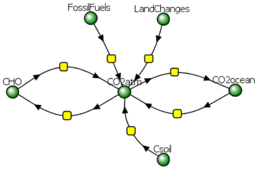
Figure \(\PageIndex{7}\): More complicated Vcell climate model.
Fortunately, we don't have to rely on these simple models to predict future trends in temperature and CO2. A complex dynamic model simulator in accordance with many different climate models is available at your fingertips. Developed at MIT and Climate Interactive, and available in any web browser, the EN-ROADS program allows users to adjust sliders for key inputs and view forecasted future temperatures and CO2 levels. In line with RCP and IPCC SSP pathways that link future emissions to socio-economic policies (discussed in Chapter 31.1), the program allows users to adjust variables such as carbon pricing and incentives to transition to clean energy across the transportation, building, and energy supply sectors. Access the program directly from this page by clicking the Close icon in the program window in Figure \(\PageIndex{8}\) below.
Figure \(\PageIndex{8}\): EN-ROADS global climate simulator
Here is also an external link to the En-Roads global climate simulator (Developed by Climate Interactive, the MIT Sloan Sustainability Initiative, and Ventana Systems).
Move the interactive sliders to see how they affect greenhouse gas emissions and global temperatures. Here is a link to a one-page tutorial on how to use them.
At this climate meeting in Dubai, delegates agreed to "the need for deep, rapid and sustained reductions in greenhouse gas emissions in line with 1.5 °C pathways and called on Parties to contribute to the following global efforts, in a nationally determined manner, taking into account the Paris Agreement and their different national circumstances, pathways and approaches". These included:
(a) Tripling renewable energy capacity globally and doubling the global average annual rate of energy efficiency improvements by 2030;
(b) Accelerating efforts towards the phase-down of unabated coal power;
(c) Accelerating efforts globally towards net-zero emission energy systems, utilizing zero- and low-carbon fuels well before or by around mid-century;
(d) Transitioning away from fossil fuels in energy systems in a just, orderly, and equitable manner, accelerating action in this critical decade to achieve net zero by 2050 in keeping with the science;
(e) Accelerating zero- and low-emission technologies, including, inter alia, renewables, nuclear, abatement and removal technologies such as carbon capture and utilization and storage, particularly in hard-to-abate sectors, and low-carbon hydrogen production;
(f) Accelerating and substantially reducing non-carbon-dioxide emissions globally, including in particular methane emissions, by 2030;
(g) Accelerating the reduction of emissions from road transport on a range of pathways, including through the development of infrastructure and rapid deployment of zero- and low-emission vehicles;
(h) As soon as possible, phase out inefficient fossil fuel subsidies that do not address energy poverty or just transition.
Here is a link to an EN-ROADS climate model that shows the effects of the actions recommended at COP28. Explore the model by moving sliders and returning them to the preset positions. These models show that aggressive action in all sectors contributing to climate change would bring down projected temperature increases to 1.7 0C (3 0F), still above the 1.5 0C limit. Of course, this assumes that the world has the political will to carry them out.
COP28 was held in a "petrostate" whose main source of revenue is fossil fuels (30% of its GDP comes from them). At the start of the meeting, it was unclear if any strides could be made to reduce fossil fuel production and use. The fossil fuel industry has been (and likely still is) a main source of misinformation on climate change. One example is documented below.
We should all be skeptical of models, especially ones that predict changes 80 or more years into the future. We gain confidence in a model if it accurately fits data from the past and the future. We mentioned in Chapter 31.1 that oil company scientists knew of the likely climatic effects of fossil fuel emissions, but the company executives did not act on their models. Their models were startlingly accurate, as shown in Figure \(\PageIndex{9}\) below, which shows their predictions for both CO2 levels and the associated increases in temperature caused by them.
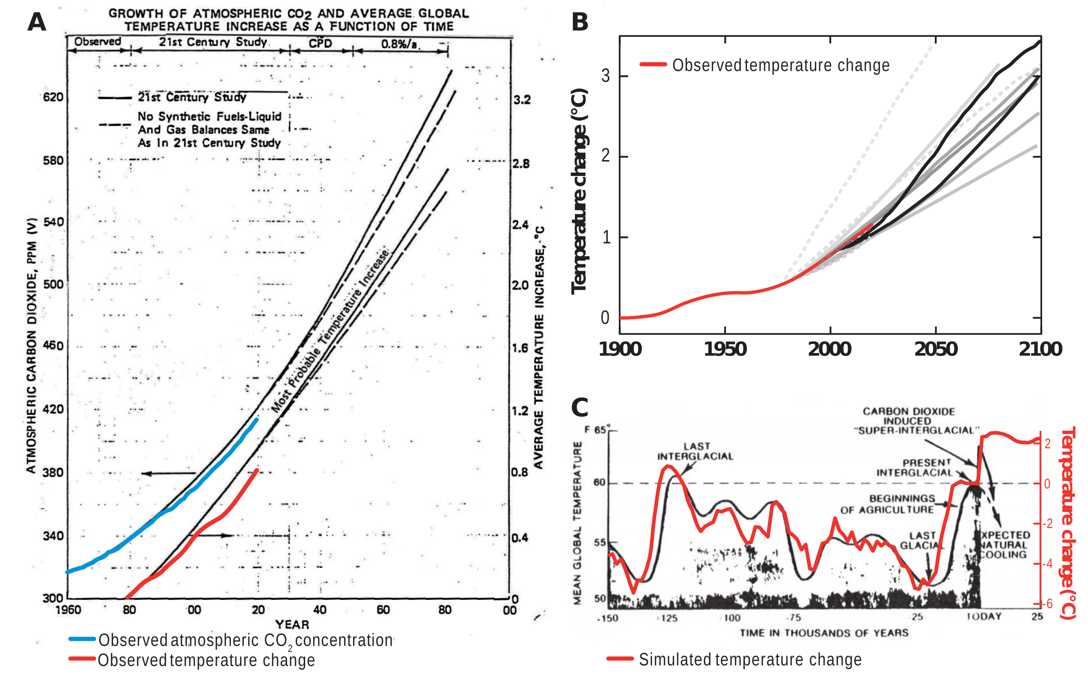
Figure \(\PageIndex{9}\): Historically observed temperature change (red) and atmospheric carbon dioxide concentration (blue) over time, compared against global warming projections reported by ExxonMobil scientists. Supran, G., Rahmstorf, S., and Oreskes, N. Assessing ExxonMobil's global warming projections. Science (2023). https://www.science.org/doi/abs/10.1...cience.abk0063. Reprinted with permission from AAAS. Not for reuse.
Panel (A) shows “Proprietary” 1982 Exxon-modeled projections.
Panel (B) summarizes projections in seven internal company memos and five peer-reviewed publications between 1977 and 2003 (gray lines).
Panel (C) shows a 1977 internally reported graph of the global warming “effect of CO2 on an interglacial scale.” (A) and (B) display averaged historical temperature observations. In contrast, the historical temperature record in (C) is a smoothed Earth system model simulation of the last 150,000 years.
As these graphs clearly show, oil companies have known for over 40 years, since the late 1970s, of the climatic effects of CO2 emissions. They could even predict the temperatures since the last ice age. In the 70s, solar and wind energy were much more expensive to produce and use than they are now. Still, if we had subsidized their development back then, as we have done for decades for the fossil fuel industry, our current climate situation would be much less precarious.
"Company executives chose to publicly denigrate climate models, insist there was no scientific consensus on anthropogenic climate change, and claim the science was highly uncertain when their own scientists were telling them the opposite" (ref). They also propagated the myth that the global climate was actually cooling. This is a powerful and unsettling example of disinformation with enormous consequences.
For more information on subsidies, visit the link below.
Click below.
- Answer
-
The figure below shows worldwide fossil fuel subsidies in US$ billion and as a percentage of global GDP from 2015 to 2025.
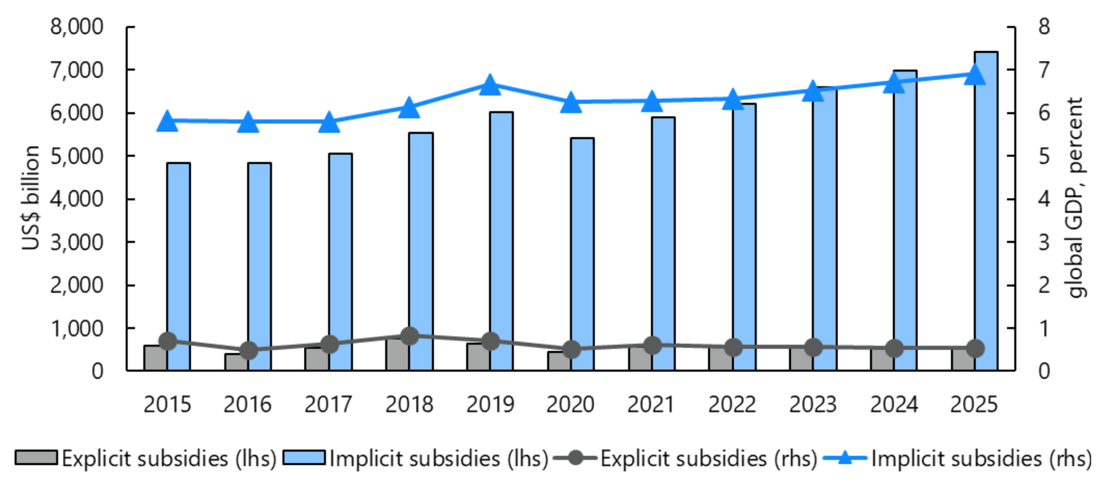
Worldwide subsidies in US $billion and in % global GDP. The bar graphs are for US$biillons, and the circles and triangles are for % global GDP. IMF. https://www.imf.org/en/Publications/W...bsidies-466004
The subsidies are broken down into explicit subsidies (tax breaks or direct payments to help fossil fuel companies cover their uncompensated costs) and implicit subsidies (undercharging for the environmental costs of fossil fuel use that oil companies don't pay). These latter "hidden" costs are passed down to countries, states, and individuals. In 2020, global subsidies totaled $5.9 trillion, or 6.8% of global GDP. The explicit subsidies given to fossil fuel companies, about 8% of the total, amounted to $472 billion just in 2020!
The figure below shows just explicit subsidies (data from the IEA and graphs from Our World in Data).
Explicit subsidies make fossil fuels cheaper, which certainly helps people with limited resources. In 2022, the world increased explicit subsidies to help defray increased consumer energy costs arising from the war in Ukraine. Explicit subsidies hide the true cost of fuel and energy.
The fossil fuel industry is mature and has benefited from explicit subsidies (dating back to 1916, with the Intangible Drilling Costs subsidy for drilling and well-preparation expenses). Back then, subsidies were needed to promote this industry, which helped many out of poverty and provided cheap energy for economic development and people's welfare. We didn't know the actual cost to biosphere health and a stable climate. Clean energy is not a mature industry and needs subsidies to grow. The IEA Government Energy Spending Tracker documents governmental spending on all types of energy, including clean energy and short-term support, to help industry and people pay energy costs. The IEA shows that from 2020 to 2023, governments worldwide spent about $1.34 trillion on clean energy investment, exceeding subsidies for fossil fuels (which are necessary to grow the clean energy sector). Short-term energy affordability measures aim to help shield consumers and industries facing soaring energy prices. Likewise, they have spent $900 billion (over and above existing dollars) to assist consumers with higher energy costs.
Now that we have seen the big picture, let's look at how carbon moves through various pools of carbon-containing molecules. We have discussed photosynthesis in detail in Chapter 20, so we will focus more on dissolved inorganic carbon (DIC), including species such as HCO3- and CO32-. Another view of the carbon cycle that includes the weathering of rocks to produce silicates and bicarbonates, along with the formation of shells in the ocean from HCO3-, CO32-, and silicates, is shown in Figure \(\PageIndex{10}\).
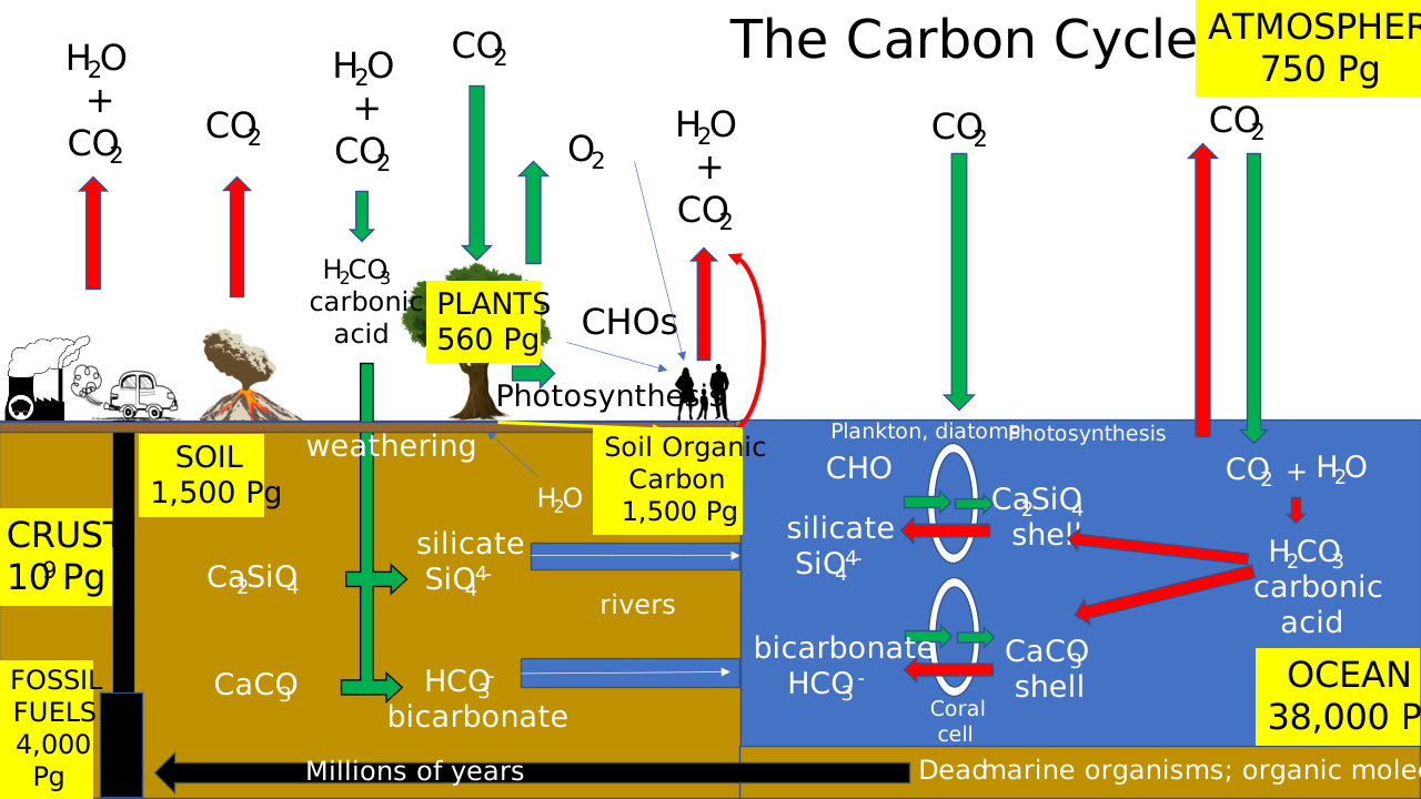
Figure \(\PageIndex{10}\): Another view of the carbon cycle
Let's focus on the oceans first. The reversible movement of CO2 from the atmosphere to the oceans, CO2 atm ↔ CO2 ocean, depends on the difference in the partial pressures of CO2 (ΔpCO2) in the atmosphere and surface waters. The reaction is also driven to the right by the removal of CO2 (aq), which forms carbonic acid (H2CO3), which then reacts to form bicarbonate (HCO3–) and carbonate (CO32–). These coupled reactions chemically buffer ocean water, thus regulating ocean pCO2 and pH.
pCO2 is not homogeneous in ocean surface waters and varies with current and temperature conditions. CO2 can be more readily released from upwellings of nutrient-rich and warm waters, especially in the tropics. In cold Northern waters and the Southern Ocean, where water sinks, it is taken up from the atmosphere (again, CO2 is more soluble in cold water).
As we discussed in Chapter 31.1, ocean chemistry of CO2 largely determines atmospheric CO2 levels. The coupled reactions of CO2 in the oceans are shown below.
\begin{equation}
\mathrm{CO}_2(\mathrm{~g}, \mathrm{~atm}) \leftrightarrow \mathrm{CO}_2(\mathrm{aq}, \text { ocean) }
\end{equation}
\begin{equation}
\mathrm{CO}_2(\mathrm{aq} \text {, ocean })+\mathrm{H}_2 \mathrm{O}(\mathrm{I} \text {, ocean }) \leftrightarrow \mathrm{H}_3 \mathrm{O}^{+}(\mathrm{aq})+\mathrm{HCO}_3^{-}(\mathrm{aq})
\end{equation}
\begin{equation}
\mathrm{H}_2 \mathrm{O}(\mathrm{I})+\mathrm{HCO}_3^{-}(\mathrm{aq}) \leftrightarrow \mathrm{H}_3 \mathrm{O}^{+}(\mathrm{aq})+\mathrm{CO}_3{ }^{2-}(\mathrm{aq} \text {, sparingly soluble })
\end{equation}
These reactions should be familiar to all chemistry students and were presented previously in Chapter 31.1 and in Chapter 2. A significant source of oceanic bicarbonate is the weathering of rocks such as limestone and marble, both of which are forms of CaCO3. The relevant reactions are shown below.
\begin{equation}
\begin{aligned}
&\mathrm{CaCO}_3(\mathrm{~s})+\mathrm{H}_2 \mathrm{O} \leftrightarrow \mathrm{Ca}^{2+}(\mathrm{aq})+\mathrm{CO}_3{ }^{2-}(\mathrm{aq}) \\
&\mathrm{CO}_3{ }^{2-}(\mathrm{aq})+\mathrm{H}_2 \mathrm{O} \leftrightarrow \mathrm{HCO}_3{ }^{-}(\mathrm{aq})+\mathrm{OH}^{-}(\mathrm{aq})
\end{aligned}
\end{equation}
CO2 is nonpolar and not very soluble in water. Either is CO32- in the presence of divalent cations like Ca2+. However, HCO3- is and can be considered a "soluble" form of carbon. This soluble form from terrestrial weathering enters rivers and eventually reaches the ocean. It is also the form of carbonate that is transferred into cells by anion transporters for eventual shell formation. HCO3- is also a chief regulator of both blood and ocean pH. Weathering is slow compared to anthropogenic CO2 emissions from fossil fuel use, but it is nevertheless a key player in the carbon cycle and in regulating ocean pH.
The same weathering reactions on silicate rocks lead to the transfer of silicate ions into rivers and the ocean, where diatoms use them to form CaSiO4 shells. As oceans absorb more CO2, they become more acidic, mimicking the effects of "weathering" on the shells of living organisms, potentially leading to their death. Silicon is directly underneath carbon in the periodic table, so the simplified reaction is analogous to those we see with CO2 and its inorganic ions.
\begin{equation}
\mathrm{H}_4 \mathrm{SiO}_4=\mathrm{SiO}_2+2 \mathrm{H}_2 \mathrm{O}
\end{equation}
H4SiO4 is silicic acid.
13C/12C ratios in ice core and ocean sediments
We can now explore how carbon isotopes can be used for more than radio-14C dating, which is quite limited in climate studies. However, 13C, a stable isotope of carbon, is extremely useful because C-13C bond dynamics are influenced by it. Reaction rates are affected by the presence of 13C when C-C bonds are made or cleaved. This isotope effect leads to different 13C/12C ratios in reactants and products, resulting in different δ13C values.
Isotopes have a long history in the study of biochemical reactions. The kcat and kcat/KM values for enzyme-catalyzed reactions can be affected if the rate-limiting step involves cleavage or the creation of a C-13C, C-D (deuterium), or C-T (tritium) bond. Substrates labeled with the isotopes have similar transition state energies for the formation/cleavage of a bond involving an isotope. Still, the ground state vibrational energy for the isotope-substituted atom is proportionately lower, as illustrated in Figure \(\PageIndex{11}\).
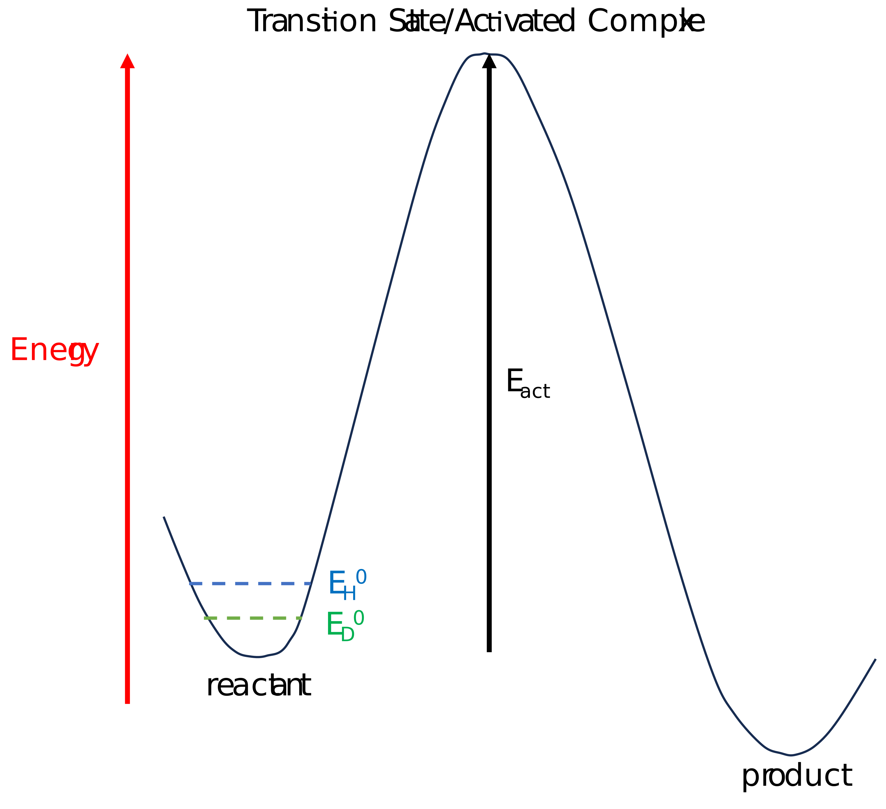
Figure \(\PageIndex{11}\): Kinetic Isotope Effects.
This primary kinetic isotope effect leads to a higher activation energy for bond formation or cleavage involving the isotope. For C-D and C-T bond cleavages that are rate-limiting, the rates are 7X and 16X slower than the cleavage of a C-H bond, respectively. Cleavage or formation of bonds to heavy isotopes of carbon, oxygen, nitrogen, sulfur, and bromine has much smaller isotope effects (ranging from 1.02 to 1.10). The difference in the magnitude of the kinetic isotope effect is directly related to the percentage change in mass. Large effects are observed when hydrogen is replaced with deuterium because the mass difference is very large (mass is doubled).
Hence, the kinetic isotope effect is at play in carbon fixation in photosynthesis. This is evidenced by the observation that 13C/12C ratios are lower in plants than in the atmosphere, showing that 12CO2 is preferentially "fixed" in the ribulose bisphosphate carboxylase/oxygenase reaction in plants and other photosynthetic organisms. Also, 12CO2, a lighter molecule, diffuses more rapidly through the stomata, which are regulated pores in leaves that facilitate the passage of CO2, O2, and H2O.
Chapter 31.2 discussed using δ18O values in ice and ocean core sediments to measure past CO2 and temperatures.
\[\delta^{18} O=\left[ \dfrac{\left(\dfrac{^{18} O}{^{16} O}\right)_{\text {sample }}}{\left(\dfrac{^{18} O}{^{16} O}\right)_{\text {reference }}}-1\right] * 1000 \nonumber \]
δ18O values for ice core water samples were easier to interpret than δ18O values for CaCO3 samples since the deposition of ice is a simple physical process compared to the complexity of the deposition of CaCO3 in ocean sediments, which depends on chemical reactions and nonequilibrium processes (as described in Chapter 31).
Climate scientists can determine and use δ13C values as well. An analogous equation for it is shown below.
\(
\delta^{13} C=\left[\dfrac{\left(\frac{13}{12} C\right)_{\text {sample }}}{\left(\frac{13}{12} \mathrm{C}\right)_{\text {reference }}}-1\right] * 1000
\)
Compared to using δ18O in carbonate samples, using δ13C is also more difficult. The shells of ocean sediment foraminifera were made from dissolved inorganic carbon (DIC) in the ocean at the time, so their δ13C values reflect that. However, shell formation is not a simple equilibrium process, since biological shells form rapidly; hence, kinetic effects in carbonate and, by extension, isotope fractionation are important. In addition, the biochemistry of shell formation is complicated.
In the open ocean, planktic foraminifera are perhaps the most important marine organisms that form shells, given that they produce and export about 2.9 Gt CaCO3/yr into the sea. Their shells form in a process involving many metastable calcite phases. It starts with a soft template that contains Mg2+ and Na+ ions, which play a key role in crystallization. Growth occurs by successive additions of "chambers" to the shell. An F-actin mesh that forms microtubular structures leads to the formation of protective envelopes during chamber formation. The layered templates sequester and help control shell mineralization, separate bulk seawater, and favor an intracellular vs. extracellular process for biomineralization. Seawater containing minerals becomes vacuolized in a process that excludes a competing cation, Mg2+, for some foraminifera. In addition, both Ca2+ and HCO3- transporters are required. This combination forms an environment low in Mg2+ and supersaturated in Ca2+ and CO32- for calcite formation. The kinetic fractionation of 13C isotopes into shells is also different from that for 18O isotopes since the "pool" of oxygen in the oceans is much greater than that of carbon. Likewise, the δ13C is more location-dependent than the δ18O.
Buried organic matter can also be studied. The δ13C value for buried organic matter depends on primary land and ocean productivity. As mentioned above, autotrophs preferentially take up 12CO2. Heterotrophs that eat them also become enriched in 12C. Hence, organisms have negative δ13C values, typically around −25‰, which depend on the pathways of incorporation and metabolism. Methane in oceanic hydrates can be either biogenic, produced by methanogens at low temperatures, or thermogenic, produced during high-temperature reactions. Biogenic methane has a δ13C of around -60‰, while thermogenic methane has a value of around −40‰. Terrestrial plants have different δ13 values. δ13C in C4 plants range from -16 to −10‰ while for C3 plants they range from −33 to −24‰.
Correction: 5/2/26)
Changes in δ¹³C in ocean sediments and ice cores are used in climate studies (just as are δ18O values in ice cores and deposited shells in ocean sediments). The following explanation of changes in δ¹³C values may help those with a chemistry-centric view of biochemistry who struggle with mass balance across the whole biosphere.
Photosynthesis strongly favors ¹²CO₂ over ¹³CO₂ in both land plants and marine phytoplankton, as described above. Hence, living organic matter is depleted in ¹³C relative to the inorganic carbon reservoir. When photosynthesis (primary production) is high, the organic material on death is buried in sediments before entering the inorganic pool. Hence ¹²C is effectively removed from the ocean's dissolved inorganic carbon (DIC) pool. The residual DIC becomes increasingly enriched in ¹³C, and carbonate minerals (including the calcite shells of foraminifera) precipitated from the DIC pools are correspondingly higher (more positive δ¹³C values). This rise is called a positive δ¹³C excursion, and it signals periods when life was productive and carbon burial was robust.
During mass extinction events, when both terrestrial and marine primary production drop precipitously, organic carbon burial slows dramatically. ¹²C that would otherwise have been sequestered in sediments instead accumulates in the ocean-atmosphere carbon pool, driving DIC, and carbonate δ¹³C toward more negative values. This is called a negative δ¹³C excursion and is a characteristicsignature in the sedimentary recordat major extinction events, such as the Permian–Triassic and Cretaceous–Paleogene boundaries.
What is tricky to understand is the difference between sedimentary carbonate δ¹³C values and ice-core δ¹³C values in sequestered CO2. These are related yet distinct.
- Ocean core carbonate δ¹³C reflects past ocean DIC reservoirs and is the primary source of positive and negative δ¹³C excursions over geological time frames of millions of years.
- Ice-core δ¹³C of trapped CO₂ directly reflects past atmospheric composition, but extends back only ~800,000 years, so it can't capture mass extinctions.
Examples of climatic events accompanied by changes in δ13C.
Negative excursions
Extrinction events are best seen in negative δ¹³C excursionin ocean sediments, although one, the PETM (below) is particularly clear in the sedimentary record. The most dramatic negative excursions are associated with mass extinctions and rapid disruptions of the carbon cycle.
- The Permian–Triassic boundary (~252 Ma) records a drop of 3–8‰ in marine carbonate sections worldwide — one of the largest and most abrupt negative excursions in the Phanerozoic, coinciding with the largest mass extinction in Earth history and likely reflecting a catastrophic collapse of marine productivity combined with massive volcanic CO₂ injection from the Siberian Traps.
- The Cretaceous–Paleogene boundary (~66 Ma) shows a sharp negative excursion of 2–3‰ in both planktonic foram carbonates in ocean sediment cores and in bulk carbonate from terrestrial and marine sections, reflecting the productivity collapse following the Chicxulub impact.
- The Paleocene–Eocene Thermal Maximum (PETM, ~56 Ma) is characterized by a negative carbon isotope excursion of 3–5‰ recorded globally in marine sediments, soil carbonates, and terrestrial organic matter — caused by a massive injection of isotopically light carbon into the ocean-atmosphere system, the source of which is still debated (methane hydrates, volcanic carbon, or a combination).
Positive excursions
- The Lomagundi–Jatuli event (~2.2–2.1 GYa) is the largest known positive δ¹³C excursion in Earth history — carbonate rocks from this period record values of +8 to +12‰, far above the typical marine carbonate value of ~0‰, suggesting a huge burial of organic carbon possibly in the Great Oxidation Event (when atmospheric O2 dramatically increased from near zero to 0.1-2%).
- The Neoproterozoic (1,000 MYA to 541 MYA) time frame is the final era of the Precambrian. During this time, Earth faced t extreme climate changes (Snowball Earth), supercontinent fragmentation, and the rise of complex, multicellular life. This era had many large positive excursions (with a few interspersed negative ones). The early Cambrian also records a large positive excursion coinciding with the diversification of animal life and increased burial of organic carbon.
More Recent changes in δ13C
1500-1650 CE
We examined δ18O values during the Little Ice Ages in Chapter 31.2. What about δ13C values? CO2 and δ13C values from 1000 to 1900 are shown in Figure \(\PageIndex{12}\).
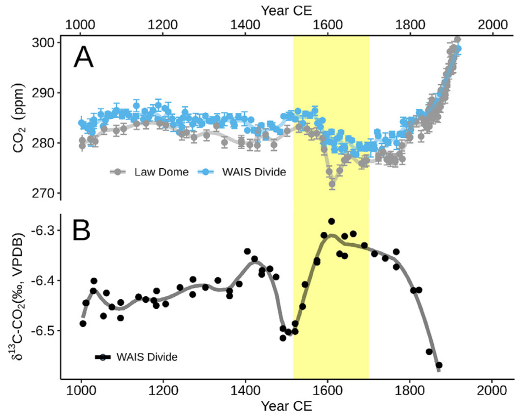
Figure \(\PageIndex{12}\): CO2 and δ13C values from 1000 to 1900. Koch et al. Quaternary Science Reviews, 207, 2019, 13-36. https://doi.org/10.1016/j.quascirev.2018.12.004. CC BY license (http://creativecommons.org/licenses/by/4.0/).
Panel (A) shows the CO2 concentrations recorded in two Antarctic ice cores: Law Dome (grey, MacFarling Meure et al., 2006) and West Antarctic Ice Sheet (WAIS) Divide (blue, Ahn et al., 2012).
Panel (B) shows the carbon isotopic ratios recorded in CO2 from the WAIS Divide ice core (black, Bauska et al., 2015), showing an increased terrestrial carbon uptake over the 16th century (B). The yellow box spans the major indigenous depopulation event (1520 - 1700 CE). Loess smoothed lines for visual aid.
Koch et al have strong evidence to suggest that the cooling after 1510 (area in the yellow box in the above figure) was associated with a dip in CO2 caused by the reforestation of Indigenous peoples' land in Meso and South America after epidemics of European disease killed upwards of 90% (around 55 million) of the indigenous peoples. The open and agricultural land reverted to forests. The diseases included smallpox, measles, influenza, the bubonic plague, malaria, diphtheria, typhus, and cholera. Domesticated farm animals introduced from Europe to the Americas were responsible for most of the disease. Along with the deaths of so many people came a concomitant return of cleared and agricultural lands (about 56 million hectares, or 212,000 mi2) to forest and plant growth. This may have led to a 7-10 ppm drop in CO2 in the late 1500s and early 1600s, peaking in 1601 (middle of the yellow box). This decrease in temperature was associated with a small rise (small positive excursion) in the δ13C values, as 12CO2 was preferentially removed from the atmosphere. Global surface air temperatures decreased by around 0.15 oC. This "Great Dying" of Indigenous peoples shows the power of humankind to globally alter the climate in calamitous ways, even before the use of fossil fuels. The decrease in δ13C values before 1500 was unexplained.
1800 to the present
δ13C values can also be used to show that the increase in CO2 since the industrial revolution is due to the burning of fossil fuels, which is of biogenic origin and hence has more negative δ13C values. Figure \(\PageIndex{13}\) shows atmospheric CO2 levels in ppm plotted along with δ13C values. There is a perfect correlation between the rise in atmospheric CO2 from the Industrial Revolution onward and the decrease in δ13C values.
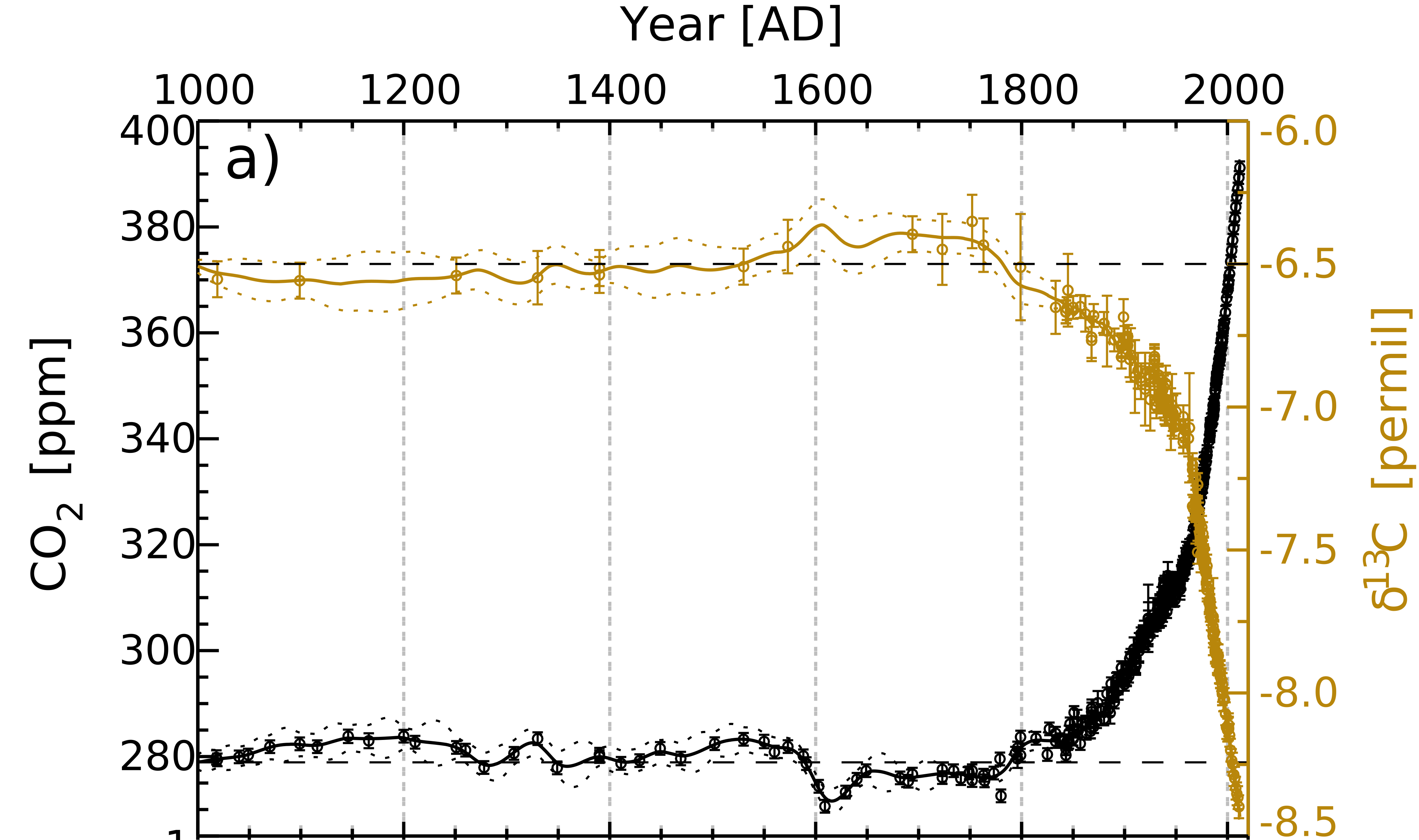
Figure \(\PageIndex{13}\): CO2 concentration (black circles) and the δ13C (brown circles) from 1000 to 2010. Rubino et al. Journal of Geophysical Research: Atmospheres. https://doi.org/10.1002/jgrd.50668. With permission (Copyright Clearance Center). another link: https://www.researchgate.net/figure/...fig1_393188182
Figure \(\PageIndex{14}\) below summarizes theδ13C values in four carbon reservoirs (atmosphere, terrestrial, ocean, and buried sediments).
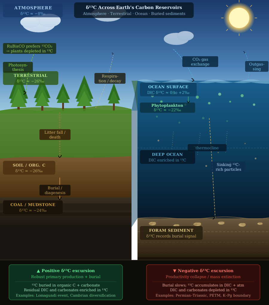
Figure \(\PageIndex{14}\): δ13C values in four carbon reservoirs (atmosphere, terrestrial, ocean, and buried sediments). Anthropic. (2025). Claude (Claude Sonnet 4.6) [Large language model]. Retrieved May 2, 2025, from https://claude.ai
The Methane Cycle
CH4 is mentioned only indirectly above as it contributes to CO2 "equivalent" emissions. As mentioned in Chapter 32.01a, methane is a much more potent greenhouse gas, with a global warming potential (GWP) 30x that of CO2 in the first 20 years of its release. It has a much shorter lifetime in the atmosphere due to chemical reactions that destroy it, so a given amount of released methane contributes to warming only over decades. However, of the total warming observed over the last 100 years, if CO2 has contributed 1 unit of warming, CH4 has contributed 0.6 units. Its concentration has increased 2.6x since the Industrial Revolution, and its rise is accelerating. Hence, we must move to limit the rise in anthropogenic CH4, mainly from fossil fuel production (leakage during production, transport, and storage) and agricultural practices. Figure \(\PageIndex{15}\) below shows sources and sinks for CH4, with orange showing anthropogenic contributions, green natural ones, and hatched a combination. 2/3 of the release is anthropogenic.

Figure \(\PageIndex{15}\): The global methane budget (Tg CH4 yr−1) for the year 2020 based on top-down methods for natural sources and sinks (green), anthropogenic sources (orange), and mixed natural and anthropogenic sources (hatched orange-green for 'Biomass and biofuel burning' and 'Combined wetland & inland freshwaters'). R B Jackson et al 2024 Environ. Res. Lett. 19 101002. DOI 10.1088/1748-9326/ad6463. Creative Commons Attribution 4.0 license.
There was a sharp spike in atmospheric methane in 2020 and 2021, but the source was unclear. δ13CCH4 measurement (which gives a measure of 13C/12C ratio of CH4) for samples from around the world over time significantly decreased in those years. This suggests that the likely source of increased emissions was microbes from wetlands, waste storage, and livestock, characterized by δ13CCH4= –62‰. Burning of biomass and biofuel is characterized by δ13CCH4 values of –24‰, while fossil fuel CH4 emissions are about –45‰.
Figure \(\PageIndex{16}\) below shows the result of computer simulations (solid, dashed, and dotted lines) that attempt to partition the increases in CH4 atm into contributions from fossil fuels (FF) and microbes (MICR). The actual values are shown as green diamonds. OH represents the hydroxyl radical, which helps scrub the atmosphere of methane; we will ignore this for this discussion. The top part shows the increase in CH4 concentrations. In 2008, the slope increased, then again in 2014, and yet again in 2021. (The bottom part of the graph shows that the overall δ13CCH4 becomes increasingly negative starting around 2008 in ways that paralleled the increases in CH4 atm.

Figure \(\PageIndex{16}\): (A) Modeled response of CH4 mole fraction and δ13CCH4 due to different CH4 growth drivers. Fossil-fuel emissions (FF), microbial emissions (MICR), hydroxide (OH). Modified from S.E. Michel, X. Lan, J. Miller, P. Tans, J.R. Clark, H. Schaefer, P. Sperlich, G. Brailsford, S. Morimoto, H. Moossen, J. Li, Rapid shift in methane carbon isotopes suggests microbial emissions drove record high atmospheric methane growth in 2020–2022, Proc. Natl. Acad. Sci. U.S.A. 121 (44) . e2411212121, https://doi.org/10.1073/pnas.2411212121 (2024). Creative Commons Attribution License 4.0 (CC BY).
The decrease in δ13CCH4 best be accounted for by increasing microbial emissions, but if emission increases were only from MICR, the observed δ13CCH4 would be even more negative. To make the decrease less negative, the best-fit model required increases in FF emission. Further increases in both (but mostly MICR) occurred in 2014. The final increase in 2021 and 2022 was from only MICR. Hence, it is likely that 85% of CH4 growth from 2007 to 2020 was due to increased microbial emissions. This is very worrisome, as it implies that global warming and climate change drive greater microbial methane production, amplifying greenhouse warming in a positive and deleterious feedback loop. What's worse, it is happening now! Here is a link to the NOAA site on atmospheric CH4 levels.
 A paper published in February 2026 showed that the sharper rise in atmospheric methane in the period 2020-2023 was likely caused by reductions in the atmosphere's scrubber for CH4, the hydroxyl free radical (OH.), along with increasing emissions of biological methane. (P. Ciais et al., Why methane surged in the atmosphere during the early 2020s. Science 391, eadx8262(2026). DOI:10.1126/science.adx8262.)
Carbon Tracker is a website that tracks methane emissions detected by satellites. In the upper-left corner, click Show Filters, then check only CH4 to track emissions. Expand the map to see individual contributors to emissions.
There are no "chemical" scrubbers for emitted CO2 in the atmosphere. Fortunately, there is for CH4, which accounts for the much shorter lifetime of atmospheric methane. The scrubber is the atmospheric hydroxyl radical, •OH, which is formed photochemically continuously during daylight hours. Its formation during daylight hours is shown in Figure \(\PageIndex{17}\) below.

Figure \(\PageIndex{17}\): The hydroxyl free radical concentration in the atmosphere. Detergent-like Molecule Recycles Itself in the Atmosphere. https://science.nasa.gov/earth/earth...sphere-144358/
You can see the hydroxyl radical is formed in daylight hours, suggesting a photocatalytic cycle. It is produced by this reaction of ozone:
O3 + hν (λ < 320 nm) → O(¹D) + O2, where O(¹D) is single oxygen, more reactive than triplet oxidation as we discussed in 12.3: The Chemistry and Biochemistry of Dioxygen
Then the singlet O reacts with water vapor:
O(¹D) + H₂O → 2 •OH
The free radical then abstracts, in a rate-limiting step, a hydrogen atom from CH4 to form the methyl free radical, •CH3.
CH4 + •OH → •CH3 + H₂O
This reaction is slow, giving methane a half-life of 9-10 years in the atmosphere. The •CH3 reacts in a series of steps to form CO2.
The net photoreaction of the carbon in CH4 is:
CH4 + 2O2 → CO2 + 2 H2O
Click below.
- Answer
-
A series of other radical propagating and terminating reactions with O2 and nitric oxide in the air then occur on a faster time scale:
•CH3 + O2 → CH3OO• (methylperoxy radical)
CH3OO• + NO → CH3O• + NO2
CH3O• + O2 → HCHO (formaldehyde) + HO2
HCHO + hν → H• + HCO•
HCO• + O2 → CO + HO2
CO + •OH → CO2 + H•
H• + O2 → HO2
HO2 + NO → •OH + NO2
Summary
(Summary written by Claude, Anthropic)
This chapter develops a quantitative understanding of the global carbon cycle — its major reservoirs, the fluxes connecting them, and the chemical and isotopic tools used to track carbon movement through the biosphere — building the foundation needed to understand both past climate change and future projections.
Stocks, fluxes, and mass balance. Carbon exists in four major reservoirs: the atmosphere (~875 GtC), the terrestrial biosphere (~3,550 GtC, including permafrost, soil, and vegetation), the oceans (~39,500 GtC, dominated by dissolved inorganic carbon), and buried fossil fuels (~905 GtC). Carbon fluxes — transfers between reservoirs in GtC/yr — operate on fast timescales (ocean/atmosphere/land exchange, up to thousands of years) and slow timescales (deep sediment and rock cycling, millions of years). Before the Industrial Revolution, these fluxes were approximately balanced. Since then, fossil fuel combustion (~9.6 GtC/yr averaged over 2012–2021, rising to 9.9 GtC/yr in 2021), combined with land-use change (~1.2 GtC/yr), has overwhelmed natural sinks — land uptake (~3.1 GtC/yr) and ocean uptake (~2.9 GtC/yr) — leaving a net atmospheric accumulation of ~5.2 GtC/yr. The cumulative fossil fuel contribution since 1850 (~275 GtC) translates to a ~129 ppm rise in atmospheric CO₂, matching independent measurements precisely. Humans are now the dominant force in the global carbon cycle.
Climate modeling. Simple kinetic models of the carbon cycle — treating each reservoir's stock as a concentration and each flux as proportional to stock size via an apparent rate constant — can reproduce observed CO₂ trends and project future concentrations. Despite many simplifying assumptions, a four-term VCell model predicts atmospheric CO₂ peaking near 982 GtC (~463 ppm) around 2073 under current emissions trajectories, closely tracking the IPCC SSP1-2.6 scenario. More sophisticated models, such as the EN-ROADS simulator developed at MIT and Climate Interactive, incorporate socioeconomic pathways, policy levers, and feedback mechanisms. ExxonMobil's internal climate models from 1977–2003 — kept from the public while executives promoted disinformation — accurately predicted both CO₂ levels and temperature increases to the present day, demonstrating that the science was settled decades ago and that delay was a deliberate choice.
Ocean carbon chemistry. CO₂ partitions between the atmosphere and ocean according to the partial pressure difference (ΔpCO₂), and is drawn into solution by its conversion to carbonic acid, bicarbonate (HCO₃⁻), and carbonate (CO₃²⁻). These coupled equilibria buffer ocean pH and regulate atmospheric CO₂ levels. Rock weathering — of limestone, marble, and silicate rocks — delivers additional HCO₃⁻ and silicate ions to the ocean, supporting shell formation by foraminifera and diatoms respectively. As ocean CO₂ uptake increases with rising atmospheric concentrations (consistent with Le Châtelier's principle), ocean acidification threatens these calcifying organisms. If oceanic uptake saturates, atmospheric CO₂ accumulation will accelerate.
Carbon isotopes and δ¹³C. Stable carbon isotope ratios (¹³C/¹²C) expressed as δ¹³C values provide powerful tools for tracking carbon through the biosphere. Kinetic isotope effects — arising from the lower ground-state vibrational energy of bonds to heavier isotopes — cause photosynthesis to preferentially fix ¹²CO₂, making organic matter and fossil fuels depleted in ¹³C (δ¹³C ≈ −25‰ for C3 plants; ≈ −60‰ for biogenic methane). In ocean sediment records, high primary productivity and organic carbon burial remove ¹²C from the dissolved inorganic carbon (DIC) pool, enriching it in ¹³C and producing positive δ¹³C excursions in carbonate shells — as seen during the Lomagundi–Jatuli event (~2.2–2.1 GYa, +8 to +12‰) and the Neoproterozoic. Conversely, mass extinctions, volcanic CO₂ injection, or rapid release of isotopically light carbon drive negative δ¹³C excursions — seen at the Permian–Triassic boundary (−3 to −8‰), the Cretaceous–Paleogene boundary (−2 to −3‰), and the PETM (−3 to −5‰). In ice cores, the decline in atmospheric δ¹³C since 1800 — perfectly correlated with rising CO₂ — provides independent confirmation that the source is fossil fuel combustion. A smaller positive δ¹³C excursion in the late 1500s to early 1600s reflects the reforestation of ~56 million hectares of Indigenous land in the Americas following the Great Dying (1520–1700 CE), which killed an estimated 55 million people through European diseases and caused a measurable ~7–10 ppm dip in atmospheric CO₂ and ~0.15°C of global cooling.
The methane cycle. Atmospheric methane has increased 2.6-fold since the Industrial Revolution and contributes approximately 0.6 units of warming for every 1 unit from CO₂ over the past 100 years. Roughly two-thirds of present methane emissions are anthropogenic, from fossil fuel production and leakage, livestock, and waste. δ¹³C_CH4 analysis — exploiting the distinct isotopic signatures of microbial (≈ −62‰), fossil fuel (≈ −45‰), and biomass combustion (≈ −24‰) sources — reveals that ~85% of methane growth from 2007 to 2020 came from microbial sources, primarily wetlands and livestock, with the 2020–2022 spike driven almost entirely by microbial emissions. This is deeply alarming because it implies a positive feedback loop: global warming stimulates microbial methane production, which drives further warming. The atmosphere does possess a chemical scrubber for methane — the hydroxyl radical (•OH), produced photochemically from ozone and water vapor — which abstracts a hydrogen atom from CH₄ in the rate-limiting step, giving methane an atmospheric half-life of ~9–10 years and ultimately converting it to CO₂. No equivalent scrubber exists for CO₂, explaining the profound difference in their atmospheric lifetimes and long-term climate impacts.