Course Introduction
- Page ID
- 1341
This page is a draft and is under active development.
\( \newcommand{\vecs}[1]{\overset { \scriptstyle \rightharpoonup} {\mathbf{#1}} } \)
\( \newcommand{\vecd}[1]{\overset{-\!-\!\rightharpoonup}{\vphantom{a}\smash {#1}}} \)
\( \newcommand{\dsum}{\displaystyle\sum\limits} \)
\( \newcommand{\dint}{\displaystyle\int\limits} \)
\( \newcommand{\dlim}{\displaystyle\lim\limits} \)
\( \newcommand{\id}{\mathrm{id}}\) \( \newcommand{\Span}{\mathrm{span}}\)
( \newcommand{\kernel}{\mathrm{null}\,}\) \( \newcommand{\range}{\mathrm{range}\,}\)
\( \newcommand{\RealPart}{\mathrm{Re}}\) \( \newcommand{\ImaginaryPart}{\mathrm{Im}}\)
\( \newcommand{\Argument}{\mathrm{Arg}}\) \( \newcommand{\norm}[1]{\| #1 \|}\)
\( \newcommand{\inner}[2]{\langle #1, #2 \rangle}\)
\( \newcommand{\Span}{\mathrm{span}}\)
\( \newcommand{\id}{\mathrm{id}}\)
\( \newcommand{\Span}{\mathrm{span}}\)
\( \newcommand{\kernel}{\mathrm{null}\,}\)
\( \newcommand{\range}{\mathrm{range}\,}\)
\( \newcommand{\RealPart}{\mathrm{Re}}\)
\( \newcommand{\ImaginaryPart}{\mathrm{Im}}\)
\( \newcommand{\Argument}{\mathrm{Arg}}\)
\( \newcommand{\norm}[1]{\| #1 \|}\)
\( \newcommand{\inner}[2]{\langle #1, #2 \rangle}\)
\( \newcommand{\Span}{\mathrm{span}}\) \( \newcommand{\AA}{\unicode[.8,0]{x212B}}\)
\( \newcommand{\vectorA}[1]{\vec{#1}} % arrow\)
\( \newcommand{\vectorAt}[1]{\vec{\text{#1}}} % arrow\)
\( \newcommand{\vectorB}[1]{\overset { \scriptstyle \rightharpoonup} {\mathbf{#1}} } \)
\( \newcommand{\vectorC}[1]{\textbf{#1}} \)
\( \newcommand{\vectorD}[1]{\overrightarrow{#1}} \)
\( \newcommand{\vectorDt}[1]{\overrightarrow{\text{#1}}} \)
\( \newcommand{\vectE}[1]{\overset{-\!-\!\rightharpoonup}{\vphantom{a}\smash{\mathbf {#1}}}} \)
\( \newcommand{\vecs}[1]{\overset { \scriptstyle \rightharpoonup} {\mathbf{#1}} } \)
\(\newcommand{\longvect}{\overrightarrow}\)
\( \newcommand{\vecd}[1]{\overset{-\!-\!\rightharpoonup}{\vphantom{a}\smash {#1}}} \)
\(\newcommand{\avec}{\mathbf a}\) \(\newcommand{\bvec}{\mathbf b}\) \(\newcommand{\cvec}{\mathbf c}\) \(\newcommand{\dvec}{\mathbf d}\) \(\newcommand{\dtil}{\widetilde{\mathbf d}}\) \(\newcommand{\evec}{\mathbf e}\) \(\newcommand{\fvec}{\mathbf f}\) \(\newcommand{\nvec}{\mathbf n}\) \(\newcommand{\pvec}{\mathbf p}\) \(\newcommand{\qvec}{\mathbf q}\) \(\newcommand{\svec}{\mathbf s}\) \(\newcommand{\tvec}{\mathbf t}\) \(\newcommand{\uvec}{\mathbf u}\) \(\newcommand{\vvec}{\mathbf v}\) \(\newcommand{\wvec}{\mathbf w}\) \(\newcommand{\xvec}{\mathbf x}\) \(\newcommand{\yvec}{\mathbf y}\) \(\newcommand{\zvec}{\mathbf z}\) \(\newcommand{\rvec}{\mathbf r}\) \(\newcommand{\mvec}{\mathbf m}\) \(\newcommand{\zerovec}{\mathbf 0}\) \(\newcommand{\onevec}{\mathbf 1}\) \(\newcommand{\real}{\mathbb R}\) \(\newcommand{\twovec}[2]{\left[\begin{array}{r}#1 \\ #2 \end{array}\right]}\) \(\newcommand{\ctwovec}[2]{\left[\begin{array}{c}#1 \\ #2 \end{array}\right]}\) \(\newcommand{\threevec}[3]{\left[\begin{array}{r}#1 \\ #2 \\ #3 \end{array}\right]}\) \(\newcommand{\cthreevec}[3]{\left[\begin{array}{c}#1 \\ #2 \\ #3 \end{array}\right]}\) \(\newcommand{\fourvec}[4]{\left[\begin{array}{r}#1 \\ #2 \\ #3 \\ #4 \end{array}\right]}\) \(\newcommand{\cfourvec}[4]{\left[\begin{array}{c}#1 \\ #2 \\ #3 \\ #4 \end{array}\right]}\) \(\newcommand{\fivevec}[5]{\left[\begin{array}{r}#1 \\ #2 \\ #3 \\ #4 \\ #5 \\ \end{array}\right]}\) \(\newcommand{\cfivevec}[5]{\left[\begin{array}{c}#1 \\ #2 \\ #3 \\ #4 \\ #5 \\ \end{array}\right]}\) \(\newcommand{\mattwo}[4]{\left[\begin{array}{rr}#1 \amp #2 \\ #3 \amp #4 \\ \end{array}\right]}\) \(\newcommand{\laspan}[1]{\text{Span}\{#1\}}\) \(\newcommand{\bcal}{\cal B}\) \(\newcommand{\ccal}{\cal C}\) \(\newcommand{\scal}{\cal S}\) \(\newcommand{\wcal}{\cal W}\) \(\newcommand{\ecal}{\cal E}\) \(\newcommand{\coords}[2]{\left\{#1\right\}_{#2}}\) \(\newcommand{\gray}[1]{\color{gray}{#1}}\) \(\newcommand{\lgray}[1]{\color{lightgray}{#1}}\) \(\newcommand{\rank}{\operatorname{rank}}\) \(\newcommand{\row}{\text{Row}}\) \(\newcommand{\col}{\text{Col}}\) \(\renewcommand{\row}{\text{Row}}\) \(\newcommand{\nul}{\text{Nul}}\) \(\newcommand{\var}{\text{Var}}\) \(\newcommand{\corr}{\text{corr}}\) \(\newcommand{\len}[1]{\left|#1\right|}\) \(\newcommand{\bbar}{\overline{\bvec}}\) \(\newcommand{\bhat}{\widehat{\bvec}}\) \(\newcommand{\bperp}{\bvec^\perp}\) \(\newcommand{\xhat}{\widehat{\xvec}}\) \(\newcommand{\vhat}{\widehat{\vvec}}\) \(\newcommand{\uhat}{\widehat{\uvec}}\) \(\newcommand{\what}{\widehat{\wvec}}\) \(\newcommand{\Sighat}{\widehat{\Sigma}}\) \(\newcommand{\lt}{<}\) \(\newcommand{\gt}{>}\) \(\newcommand{\amp}{&}\) \(\definecolor{fillinmathshade}{gray}{0.9}\)Importance of Structural Geology
Structural geology allows us to unravel deformational histories and their relationships to the Earth system as a whole, helping us to understand the mechanisms of plate tectonics and its expression as fault slip in the upper crust and as plastic flow at depth. It is used in quantifying hazards related to earthquake probability and concepts such as slope stability, and involves investigation of applied mechanics of natural materials, helping us understand rock strength and hydraulic fracture (fracking). Structural geology also has economic uses, helping to find resources deformed or created by geologic structures.
Course Goals
The goals of the course are to develop your skills as a structural geologist by teaching you to visualize and interpret structural geometries and their kinematic evolution during progressive deformation and applying the principles of continuum mechanics to quantitatively relate the distribution of forces (stress) to deformation (strain) within the lithosphere. Lab work will help you to understand and apply key concepts in structural data collection and analysis, learn to generate and record structural observations to generate geologic maps and cross-sections, and write a consulting-style geologic report.
Course Overview
This course has two parts. Part 1, Brittle Deformation and Mechanics, covers faulting of various styles and introduces continuum mechanics of fault frictional strength and stability. Part 2, Strain, Rheology, and Tectonics, covers strain, analysis of folding, lineations and foliations, plastic rheology, and convergent and divergent continental tectonics.
Earth's Mechanical Layering
The outer silicate shell of the earth is divided into three mechanical layers, the lithosphere, asthenosphere, and the mesosphere.
The lithosphere is the solid, rigid outer shell that behaves in a plate-like manner. It includes all of the crust (with rare exceptions), and usually the uppermost mantle as well. The base of the crust is known as the Moho, short for Mohorovičić Discontinuity, where seismic wave velocity jumps upon entering denser mantle rocks. The thickness of the lithosphere varies dramatically with type and location. The thinnest oceanic lithosphere, found near spreading centers, can be as little as seven kilometers thick: a simple layer consisting entirely of oceanic crust. The thickest oceanic lithosphere can be up to a hundred kilometers thick, where the upper mantle has cooled underneath a comparatively thin, old layer of oceanic crust.
Continental lithosphere is thinnest where it overlies the very hot, viscous upper mantle at the thinnest fringes of active continental rifts. At these locations, the lithosphere is composed only of crust and can be less than ten kilometers thick. The thickest continental lithosphere consists of approximately 40 km of crust overlying 100 to 150 km of cold, but somewhat buoyant, upper mantle, and is found in continental cratons (interiors). The thickest continental crust, however, is approximately 70 km thick and is found beneath orogenic plateaus in the Andes and Tibet. This thick crust is underlain by very little mantle lithosphere: in general, the lithosphere is thin beneath orogens, even if the crust is thick.
The asthenosphere is the solid but viscous layer beneath the lithosphere that flows in response to density variations, driving plate tectonics. Very hot crust in rifts or thick orogens may also flow sufficiently to act as asthenosphere. (An orogen is region of continental crust undergoing deformation, usually in response to plate collision; rifting and strike-slip dominated orogens also exist.)
The mesosphere consists of the lower mantle, where mineral phases retard flow relative to the asthenosphere. Downwelling oceanic lithospheric slabs may stall at the mesosphere/asthenosphere boundary. The mesosphere still participates in mantle convection.
Structure vs. Tectonics
A geologic structure is a geometric element of rock that records displacement or deformation. Examples of geologic structures include tilted strata, faults, folds, lineations, and foliations.
Tectonics is the study of deformational history as recorded by geologic structures, and includes investigation of processes such as formation of rift basins, development of mountain ranges, and collision of continents.
In many ways, the difference is a matter of scale. Tectonic problems will often encompass numerous geologic structures and their relationships to one another, both spatially and over time; but some geologic structures are important tectonic problems in their own right, such as a plate boundary fault, or crustal-scale tilting. Structural geology alone, however, is not enough to understand the full picture of how and why continents deform: interactions with oceanic lithosphere fundamentally influence continental deformation. Until these influences -- in the form of seafloor spreading and subduction -- were discovered, many rejected Alfred Wegener's theory of continental drift due to lack of explanation of a physical mechanism to drive the proposed motions.
Plate Tectonics
Plate tectonics describes the motion of rigid plates of lithosphere around the Earth's spherical shell. This assumption that plates are rigid works for almost all oceanic lithosphere and for continental lithosphere outside of orogens, which tend to host more distributed deformation and are often poorly described by rigid plate interactions.
Interactions between lithospheric plates come in several varieties.
Divergent Margins
Divergent margins have rifted edges of continental lithosphere with adjacent oceanic lithosphere between. Continental crust becomes thinned prior to breaking and subsequent formation of oceanic lithosphere. The width and thickness of this thinned zone varies considerably from place to place, and may differ between the crust and mantle lithosphere. Volcanism often plays a major role in break-up of continents.

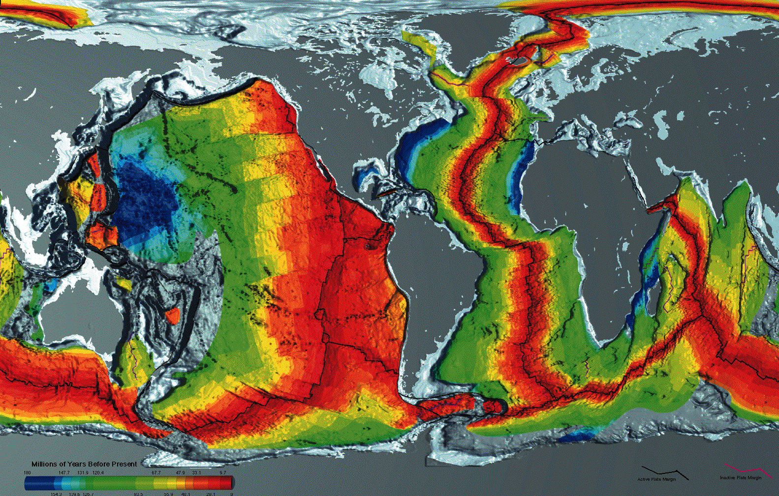
The above image is a crustal age map for the ocean floor from NOAA showing increasing age of oceanic crust away from mid-ocean ridges. Note the symmetry about mid-ocean ridges and symmetry in the Atlantic Ocean, dominated by divergent (rifted) continental margins. Most of the Pacific basin is bounded by convergent margins where oceanic crust is consumed by subduction.
Ancient rifted margins are known as passive margins because they are inactive continent edges. This contrasts with active margins, which are frequently bounded by subduction zones (though strike-slip margins, like California's, are also considered active margins).
Convergent Margin
Convergent margins come in three varieties:
- Subduction of oceanic lithosphere beneath a continent, usually with an active volcanic arc on the overriding plate.
- Subduction of oceanic lithosphere beneath oceanic lithosphere with a volcanic arc constructed on top.
- Collision of continents, with complex faulting and magmatic relationships.
Where oceanic crust is subducted beneath a continent, thick crust is found at the site of the volcanic arc. Oblique subduction may be accommodated by strike-slip faults in the overriding plate.

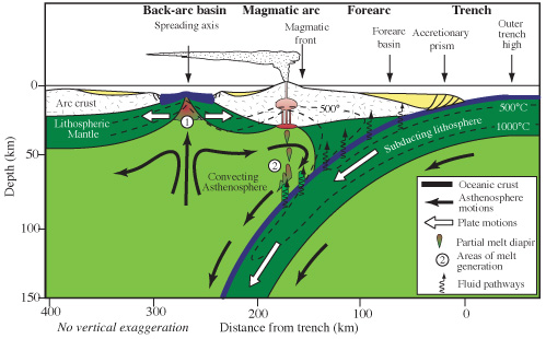
Above is a cross section of the Marianas subduction zone from the Eruptions blog (E. Klemeti). Here the Pacific plate oceanic lithosphere subducts beneath a fragment of the Philippine plate oceanic lithosphere with a volcanic arc built on top. The back-arc basin is a site of rifting and sea floor spreading in response to rollback of the Marianas subduction zone. Note the location and thickness of lithospheric mantle relative to crustal thicknesses.
Structural Models
Geometric Models
Geometric models describe the form of a geologic structure in the earth. These models are deduced from limited observations, usually made at the surface, and make no further assumptions about how the structure formed. Consideration of formation mechanisms may lead to refinement of the geometric model.
The following example of a set of observations leading to a geometric model:
- Dips of rocks change
- Age of strata first increases, then decreases across the change in dip
- Conclusion: an anticline is present
Kinematic Models
A kinematic model considers the pathway through which rocks were deformed to create the present shape of a structure. This could be as simple as the relationships between cross-cutting faults, or more elaborate relationships between folding and faulting. Both geometric and kinematic models predict displacement, the relative motion of rocks via formation of structures, but kinematic models do a better job at testing this.
The goal of a kinematic model is a cross-section that is balanced and internally consistent. When a cross-section is balanced, no holes or overlaps occur when fault slip and folding are restored; when internally consistent, fault motions are consistent with folding and cross-cutting relationships.
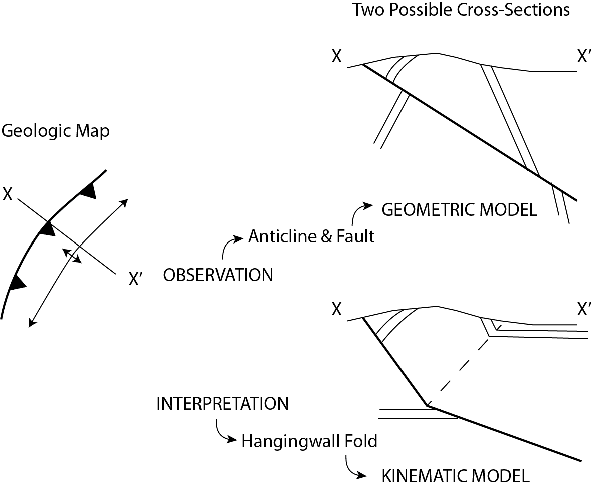
Even if structure is well understood geometrically, there may be more than one viable kinematic model to produce it. The illustration below shows two different cross-section interpretations of a geologic map.

The upper section is a simple geometric model, showing the fault cutting the adjacent anticline. The lower section is a kinematic model that interprets the folding as related to fault slip, and uses fault-bend-fold theory approach to generate a balanced cross-section.
Fault-Bend-Folding
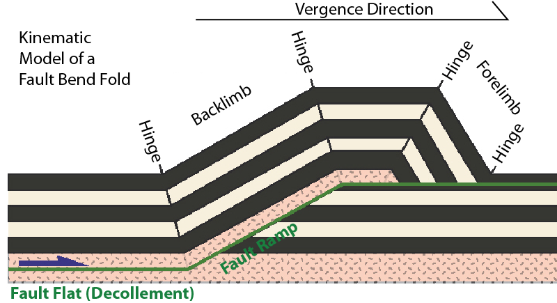
A fault-bend-fold is created as a fault ramp gives rise to a fold, developing as the hanging wall slips over the footwall. These folds have predictable geometries. The figure below illustrates some of the geometric features of this fold geometry.

Mechanical Models
A mechanical model uses forces and rock properties to deduce how a structure was formed. Like a kinematic model, mechanical models may also be non-unique, as more than one relationship affects rock deformation.
Stresses and Sign Conventions
Forces in the earth are usually termed as stresses. A stress is like a force, but there are several important differences. Stresses have units of force per area, like pressures do. Stresses are also defined to be at mechanical equilibrium, meaning all forces are balanced: thus, stress is always represented as a pair of opposing vectors. A single vector is called a traction. Finally, stresses are generally not perpendicular to a plane in the earth, so they are considered in terms of two components: normal stress and shear stress. Normal stresses are positive when compressional and negative when extensional; shear stresses are positive when sinistral (counterclockwise) and negative when dextral (clockwise). General stress is a summation of a normal stress and a shear stress.
Strain
Deformation in the earth is formally described as strain. Strain is expressed as a ratio, such as the change in length over the original length, rather than just a measurement of displacement. Like stress, there are multiple components: extension (normal) strain and shear strain.
Elongation strain, \(e= \frac{\Delta L}{L_{0}}\), is the change in length divided by the original length. Elongation strain is positive for elongation and negative for shortening.
Summary
List of Terms
- Brittle deformation
- Ductile (plastic) deformation
- Lithosphere
- Moho (Mohorovičić discontinuity)
- Craton
- Asthenosphere
- Orogen
- Mesosphere
- Geologic structure
- Structure vs. tectonics
- Plate tectonics
- Divergent (rifted) margin
- Mid-ocean ridge
- Active margin
- Passive margin
- Convergent margin
- Geometric model
- Kinematic model
- Displacement
- Fault-bend-fold
- Mechanical model
- Stress
- Traction
- Normal stress
- Shear stress
- Strain
Contributors
Michael E. Oskin (Department of Earth and Planetary Sciences, UC Davis)

