
1.4.3: Morphological development in vicinity of a port
- Page ID
- 16260

\( \newcommand{\vecs}[1]{\overset { \scriptstyle \rightharpoonup} {\mathbf{#1}} } \)
\( \newcommand{\vecd}[1]{\overset{-\!-\!\rightharpoonup}{\vphantom{a}\smash {#1}}} \)
\( \newcommand{\id}{\mathrm{id}}\) \( \newcommand{\Span}{\mathrm{span}}\)
( \newcommand{\kernel}{\mathrm{null}\,}\) \( \newcommand{\range}{\mathrm{range}\,}\)
\( \newcommand{\RealPart}{\mathrm{Re}}\) \( \newcommand{\ImaginaryPart}{\mathrm{Im}}\)
\( \newcommand{\Argument}{\mathrm{Arg}}\) \( \newcommand{\norm}[1]{\| #1 \|}\)
\( \newcommand{\inner}[2]{\langle #1, #2 \rangle}\)
\( \newcommand{\Span}{\mathrm{span}}\)
\( \newcommand{\id}{\mathrm{id}}\)
\( \newcommand{\Span}{\mathrm{span}}\)
\( \newcommand{\kernel}{\mathrm{null}\,}\)
\( \newcommand{\range}{\mathrm{range}\,}\)
\( \newcommand{\RealPart}{\mathrm{Re}}\)
\( \newcommand{\ImaginaryPart}{\mathrm{Im}}\)
\( \newcommand{\Argument}{\mathrm{Arg}}\)
\( \newcommand{\norm}[1]{\| #1 \|}\)
\( \newcommand{\inner}[2]{\langle #1, #2 \rangle}\)
\( \newcommand{\Span}{\mathrm{span}}\) \( \newcommand{\AA}{\unicode[.8,0]{x212B}}\)
\( \newcommand{\vectorA}[1]{\vec{#1}} % arrow\)
\( \newcommand{\vectorAt}[1]{\vec{\text{#1}}} % arrow\)
\( \newcommand{\vectorB}[1]{\overset { \scriptstyle \rightharpoonup} {\mathbf{#1}} } \)
\( \newcommand{\vectorC}[1]{\textbf{#1}} \)
\( \newcommand{\vectorD}[1]{\overrightarrow{#1}} \)
\( \newcommand{\vectorDt}[1]{\overrightarrow{\text{#1}}} \)
\( \newcommand{\vectE}[1]{\overset{-\!-\!\rightharpoonup}{\vphantom{a}\smash{\mathbf {#1}}}} \)
\( \newcommand{\vecs}[1]{\overset { \scriptstyle \rightharpoonup} {\mathbf{#1}} } \)
\( \newcommand{\vecd}[1]{\overset{-\!-\!\rightharpoonup}{\vphantom{a}\smash {#1}}} \)
\(\newcommand{\avec}{\mathbf a}\) \(\newcommand{\bvec}{\mathbf b}\) \(\newcommand{\cvec}{\mathbf c}\) \(\newcommand{\dvec}{\mathbf d}\) \(\newcommand{\dtil}{\widetilde{\mathbf d}}\) \(\newcommand{\evec}{\mathbf e}\) \(\newcommand{\fvec}{\mathbf f}\) \(\newcommand{\nvec}{\mathbf n}\) \(\newcommand{\pvec}{\mathbf p}\) \(\newcommand{\qvec}{\mathbf q}\) \(\newcommand{\svec}{\mathbf s}\) \(\newcommand{\tvec}{\mathbf t}\) \(\newcommand{\uvec}{\mathbf u}\) \(\newcommand{\vvec}{\mathbf v}\) \(\newcommand{\wvec}{\mathbf w}\) \(\newcommand{\xvec}{\mathbf x}\) \(\newcommand{\yvec}{\mathbf y}\) \(\newcommand{\zvec}{\mathbf z}\) \(\newcommand{\rvec}{\mathbf r}\) \(\newcommand{\mvec}{\mathbf m}\) \(\newcommand{\zerovec}{\mathbf 0}\) \(\newcommand{\onevec}{\mathbf 1}\) \(\newcommand{\real}{\mathbb R}\) \(\newcommand{\twovec}[2]{\left[\begin{array}{r}#1 \\ #2 \end{array}\right]}\) \(\newcommand{\ctwovec}[2]{\left[\begin{array}{c}#1 \\ #2 \end{array}\right]}\) \(\newcommand{\threevec}[3]{\left[\begin{array}{r}#1 \\ #2 \\ #3 \end{array}\right]}\) \(\newcommand{\cthreevec}[3]{\left[\begin{array}{c}#1 \\ #2 \\ #3 \end{array}\right]}\) \(\newcommand{\fourvec}[4]{\left[\begin{array}{r}#1 \\ #2 \\ #3 \\ #4 \end{array}\right]}\) \(\newcommand{\cfourvec}[4]{\left[\begin{array}{c}#1 \\ #2 \\ #3 \\ #4 \end{array}\right]}\) \(\newcommand{\fivevec}[5]{\left[\begin{array}{r}#1 \\ #2 \\ #3 \\ #4 \\ #5 \\ \end{array}\right]}\) \(\newcommand{\cfivevec}[5]{\left[\begin{array}{c}#1 \\ #2 \\ #3 \\ #4 \\ #5 \\ \end{array}\right]}\) \(\newcommand{\mattwo}[4]{\left[\begin{array}{rr}#1 \amp #2 \\ #3 \amp #4 \\ \end{array}\right]}\) \(\newcommand{\laspan}[1]{\text{Span}\{#1\}}\) \(\newcommand{\bcal}{\cal B}\) \(\newcommand{\ccal}{\cal C}\) \(\newcommand{\scal}{\cal S}\) \(\newcommand{\wcal}{\cal W}\) \(\newcommand{\ecal}{\cal E}\) \(\newcommand{\coords}[2]{\left\{#1\right\}_{#2}}\) \(\newcommand{\gray}[1]{\color{gray}{#1}}\) \(\newcommand{\lgray}[1]{\color{lightgray}{#1}}\) \(\newcommand{\rank}{\operatorname{rank}}\) \(\newcommand{\row}{\text{Row}}\) \(\newcommand{\col}{\text{Col}}\) \(\renewcommand{\row}{\text{Row}}\) \(\newcommand{\nul}{\text{Nul}}\) \(\newcommand{\var}{\text{Var}}\) \(\newcommand{\corr}{\text{corr}}\) \(\newcommand{\len}[1]{\left|#1\right|}\) \(\newcommand{\bbar}{\overline{\bvec}}\) \(\newcommand{\bhat}{\widehat{\bvec}}\) \(\newcommand{\bperp}{\bvec^\perp}\) \(\newcommand{\xhat}{\widehat{\xvec}}\) \(\newcommand{\vhat}{\widehat{\vvec}}\) \(\newcommand{\uhat}{\widehat{\uvec}}\) \(\newcommand{\what}{\widehat{\wvec}}\) \(\newcommand{\Sighat}{\widehat{\Sigma}}\) \(\newcommand{\lt}{<}\) \(\newcommand{\gt}{>}\) \(\newcommand{\amp}{&}\) \(\definecolor{fillinmathshade}{gray}{0.9}\)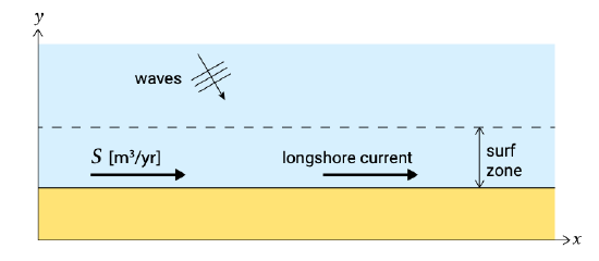
Figure 1.5 shows in plan view a part of a uniform sandy coast. Uniform means that the depth contours are assumed to be straight and parallel. Waves obliquely approach the coast, viz. there is a non-zero angle \(\varphi\) between the wave crests and the depth contours (or equivalently between a wave ray and the shore normal). As the waves approach the shore the angle becomes smaller due to refraction (Sect. 5.2.3).
Inside (and a little bit outside) the surf zone, sediment is transported along the coast, the so-called longshore transport (Ch. 8). Waves continuously stir up material from the bed. This sediment is then transported by the longshore current. This current is generated by the breaking of obliquely incident waves in the surf zone, see Sect. 5.5.5. Due to the wave action in stirring up the material, a longshore current of \(1\ m/s\) is much more effective in transporting sand than a river flow with the same magnitude.
If the coast is uniform indeed, the sediment transport \(S\) is constant along the coast and the coast remains stable. The coastal section under consideration will only change when the amount of sediment transported into the section is different than the sediment leaving the section; or in other words: when there is a gradient in longshore transport rates. Erosion will occur in the case of a positive gradient in the transport direction (the sediment transport is increasing along the shore, and hence more sediment is leaving than entering the section). Accretion occurs in the case of a negative gradient in the drift direction. A uniform sediment transport along the coast (no gradient) does not change the coast. This leads to one of the most important notions of these lecture notes:
Coastal changes occur in the case of transport gradients. A positive gradient (an increase in the sediment transport in the transport direction) leads to erosion. A negative gradient (a decrease in sediment transport in the transport direction) creates accretion. If the gradient is zero there are no changes in morphology.
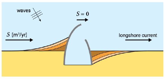
If along the uniform sandy coast a port is built with the help of two rather long break- waters, much longer than the width of the surf zone (see Fig. 1.6), the longshore sediment transport will be interrupted. Seaward of the breakwaters no sediment transport is assumed to occur. On the updrift side of the port, accumulation of sand will occur (negative transport gradient); at the downdrift side (lee side) erosion will take place (due to a positive transport gradient). In Fig. 1.6 some coastline positions have been sketched as a function of time.
After having studied these lecture notes, you should be able to understand and describe the shapes of the coastline at updrift and downdrift sides as a function of time. It is to be expected that sooner or later the accreting coastline on the updrift side reaches the end of the updrift breakwater; you should be able to say at what time after the construction of the port this will happen. For the time being it will be clear that as long as no sediment will pass the breakwaters (\(S = 0\ m^3/yr\) seaward of the breakwaters) the total accumulation of sand in \(t\) years after completion of the port on the updrift side will be \(t \times S\ m^3\) (with \(S\) the undisturbed transport rate). That is, when we assume that \(S\) in \(m^3/yr\) is expressed including pores between the grains, so that the volumes represent deposited volumes. (In Sect. 6.4 other units of sediment transport are discussed). The total erosion on the lee side will be \(t \times S\ m^3\) as well.
In most cases accumulation will not be considered problematic by the coastal zone manager involved; valuable new land has been gained (unless sediment is deposited in navigation channels). However, the erosion on the lee side of the port will sooner or later cause serious problems. How to resolve such types of erosion problems will be discussed in Ch. 10. An obvious solution will be to artificially transfer volumes of sand from the one side of the port to the other (\(S\ m^3/yr\) on average; a so-called sand bypass system). Summarizing:
Engineering problems are often related to longshore transport gradients. Structural coastal problems arise when the longshore transport is changing alongshore, for instance when the longshore current is interrupted by harbour breakwaters.
In the example of Fig. 1.6, the longshore sediment transport was due to obliquely approaching waves only. If also tidal currents occur along the coast, the morphological behaviour becomes more complicated. The combination of a wave-induced and tidal longshore current is discussed in Sect. 5.7.2.