8.0: Radiative Transfer for Satellites
- Page ID
- 9575
\( \newcommand{\vecs}[1]{\overset { \scriptstyle \rightharpoonup} {\mathbf{#1}} } \)
\( \newcommand{\vecd}[1]{\overset{-\!-\!\rightharpoonup}{\vphantom{a}\smash {#1}}} \)
\( \newcommand{\dsum}{\displaystyle\sum\limits} \)
\( \newcommand{\dint}{\displaystyle\int\limits} \)
\( \newcommand{\dlim}{\displaystyle\lim\limits} \)
\( \newcommand{\id}{\mathrm{id}}\) \( \newcommand{\Span}{\mathrm{span}}\)
( \newcommand{\kernel}{\mathrm{null}\,}\) \( \newcommand{\range}{\mathrm{range}\,}\)
\( \newcommand{\RealPart}{\mathrm{Re}}\) \( \newcommand{\ImaginaryPart}{\mathrm{Im}}\)
\( \newcommand{\Argument}{\mathrm{Arg}}\) \( \newcommand{\norm}[1]{\| #1 \|}\)
\( \newcommand{\inner}[2]{\langle #1, #2 \rangle}\)
\( \newcommand{\Span}{\mathrm{span}}\)
\( \newcommand{\id}{\mathrm{id}}\)
\( \newcommand{\Span}{\mathrm{span}}\)
\( \newcommand{\kernel}{\mathrm{null}\,}\)
\( \newcommand{\range}{\mathrm{range}\,}\)
\( \newcommand{\RealPart}{\mathrm{Re}}\)
\( \newcommand{\ImaginaryPart}{\mathrm{Im}}\)
\( \newcommand{\Argument}{\mathrm{Arg}}\)
\( \newcommand{\norm}[1]{\| #1 \|}\)
\( \newcommand{\inner}[2]{\langle #1, #2 \rangle}\)
\( \newcommand{\Span}{\mathrm{span}}\) \( \newcommand{\AA}{\unicode[.8,0]{x212B}}\)
\( \newcommand{\vectorA}[1]{\vec{#1}} % arrow\)
\( \newcommand{\vectorAt}[1]{\vec{\text{#1}}} % arrow\)
\( \newcommand{\vectorB}[1]{\overset { \scriptstyle \rightharpoonup} {\mathbf{#1}} } \)
\( \newcommand{\vectorC}[1]{\textbf{#1}} \)
\( \newcommand{\vectorD}[1]{\overrightarrow{#1}} \)
\( \newcommand{\vectorDt}[1]{\overrightarrow{\text{#1}}} \)
\( \newcommand{\vectE}[1]{\overset{-\!-\!\rightharpoonup}{\vphantom{a}\smash{\mathbf {#1}}}} \)
\( \newcommand{\vecs}[1]{\overset { \scriptstyle \rightharpoonup} {\mathbf{#1}} } \)
\(\newcommand{\longvect}{\overrightarrow}\)
\( \newcommand{\vecd}[1]{\overset{-\!-\!\rightharpoonup}{\vphantom{a}\smash {#1}}} \)
\(\newcommand{\avec}{\mathbf a}\) \(\newcommand{\bvec}{\mathbf b}\) \(\newcommand{\cvec}{\mathbf c}\) \(\newcommand{\dvec}{\mathbf d}\) \(\newcommand{\dtil}{\widetilde{\mathbf d}}\) \(\newcommand{\evec}{\mathbf e}\) \(\newcommand{\fvec}{\mathbf f}\) \(\newcommand{\nvec}{\mathbf n}\) \(\newcommand{\pvec}{\mathbf p}\) \(\newcommand{\qvec}{\mathbf q}\) \(\newcommand{\svec}{\mathbf s}\) \(\newcommand{\tvec}{\mathbf t}\) \(\newcommand{\uvec}{\mathbf u}\) \(\newcommand{\vvec}{\mathbf v}\) \(\newcommand{\wvec}{\mathbf w}\) \(\newcommand{\xvec}{\mathbf x}\) \(\newcommand{\yvec}{\mathbf y}\) \(\newcommand{\zvec}{\mathbf z}\) \(\newcommand{\rvec}{\mathbf r}\) \(\newcommand{\mvec}{\mathbf m}\) \(\newcommand{\zerovec}{\mathbf 0}\) \(\newcommand{\onevec}{\mathbf 1}\) \(\newcommand{\real}{\mathbb R}\) \(\newcommand{\twovec}[2]{\left[\begin{array}{r}#1 \\ #2 \end{array}\right]}\) \(\newcommand{\ctwovec}[2]{\left[\begin{array}{c}#1 \\ #2 \end{array}\right]}\) \(\newcommand{\threevec}[3]{\left[\begin{array}{r}#1 \\ #2 \\ #3 \end{array}\right]}\) \(\newcommand{\cthreevec}[3]{\left[\begin{array}{c}#1 \\ #2 \\ #3 \end{array}\right]}\) \(\newcommand{\fourvec}[4]{\left[\begin{array}{r}#1 \\ #2 \\ #3 \\ #4 \end{array}\right]}\) \(\newcommand{\cfourvec}[4]{\left[\begin{array}{c}#1 \\ #2 \\ #3 \\ #4 \end{array}\right]}\) \(\newcommand{\fivevec}[5]{\left[\begin{array}{r}#1 \\ #2 \\ #3 \\ #4 \\ #5 \\ \end{array}\right]}\) \(\newcommand{\cfivevec}[5]{\left[\begin{array}{c}#1 \\ #2 \\ #3 \\ #4 \\ #5 \\ \end{array}\right]}\) \(\newcommand{\mattwo}[4]{\left[\begin{array}{rr}#1 \amp #2 \\ #3 \amp #4 \\ \end{array}\right]}\) \(\newcommand{\laspan}[1]{\text{Span}\{#1\}}\) \(\newcommand{\bcal}{\cal B}\) \(\newcommand{\ccal}{\cal C}\) \(\newcommand{\scal}{\cal S}\) \(\newcommand{\wcal}{\cal W}\) \(\newcommand{\ecal}{\cal E}\) \(\newcommand{\coords}[2]{\left\{#1\right\}_{#2}}\) \(\newcommand{\gray}[1]{\color{gray}{#1}}\) \(\newcommand{\lgray}[1]{\color{lightgray}{#1}}\) \(\newcommand{\rank}{\operatorname{rank}}\) \(\newcommand{\row}{\text{Row}}\) \(\newcommand{\col}{\text{Col}}\) \(\renewcommand{\row}{\text{Row}}\) \(\newcommand{\nul}{\text{Nul}}\) \(\newcommand{\var}{\text{Var}}\) \(\newcommand{\corr}{\text{corr}}\) \(\newcommand{\len}[1]{\left|#1\right|}\) \(\newcommand{\bbar}{\overline{\bvec}}\) \(\newcommand{\bhat}{\widehat{\bvec}}\) \(\newcommand{\bperp}{\bvec^\perp}\) \(\newcommand{\xhat}{\widehat{\xvec}}\) \(\newcommand{\vhat}{\widehat{\vvec}}\) \(\newcommand{\uhat}{\widehat{\uvec}}\) \(\newcommand{\what}{\widehat{\wvec}}\) \(\newcommand{\Sighat}{\widehat{\Sigma}}\) \(\newcommand{\lt}{<}\) \(\newcommand{\gt}{>}\) \(\newcommand{\amp}{&}\) \(\definecolor{fillinmathshade}{gray}{0.9}\)8.1.1. Signals
Weather satellites have passive sensors called radiometers that measure upwelling electromagnetic radiation from the Earth and atmosphere. Infrared (IR, long-wave) and microwave radiation are emitted by the Earth, ocean, atmosphere, clouds, and the sun (see the Radiation chapter). Visible light (short-wave or solar radiation) is emitted by the sun and reflected and absorbed by the Earth system. Additional portions of the electromagnetic spectrum are useful for remote sensing.
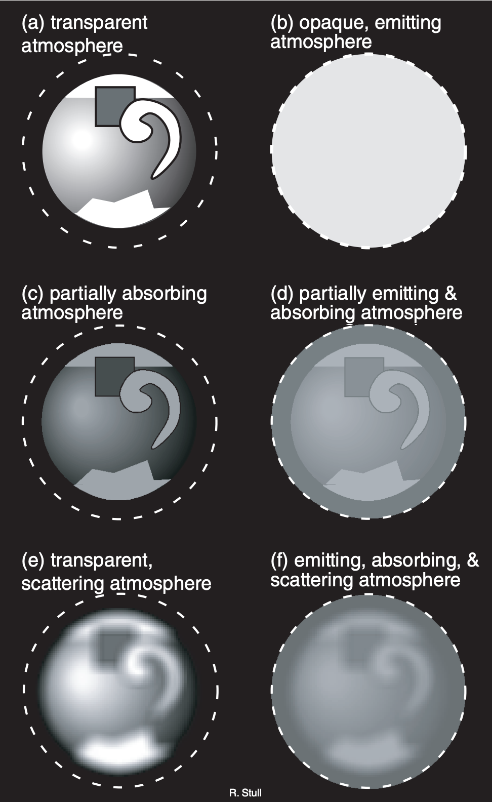
What the satellite can “see” in any one wavelength depends on the transparency of the air at that wavelength. A perfectly transparent atmosphere allows the upwelling radiation from the Earth’s surface or highest cloud top to reach the satellite. Thus, wavelengths for which the air is transparent (Fig. 8.2a) are good for observing clouds and land use.
If air molecules strongly absorb upwelling radiation at another wavelength, then none of the signal at that wavelength from the Earth and clouds will reach the satellite (i.e., an opaque atmosphere). But according to Kirchhoff’s law (see the Radiation chapter), absorptivity equals the emissivity at that wavelength. This atmosphere will emit its own spectrum of radiation according to Planck’s law, causing the atmosphere to glow like an infrared light bulb (Fig. 8.2b). Wavelengths with this characteristic are good for observing the top of the atmosphere, but are bad for remote sensing of the Earth and clouds.
For other wavelengths, the atmosphere partially absorbs the upwelling radiation, causing the Earth and clouds to look dimmer (Fig. 8.2c). But this usually never happens alone, because Kirchhoff’s law says that the atmosphere will also partially emit in the same wavelengths. The result is a dim view of the Earth, partially masked by a dimly glowing atmosphere (Fig. 8.2d).
For wavelengths scattered by air molecules, the signal from the Earth and clouds becomes blurred (Fig. 8.2e). For some wavelengths, this blurring is so extreme that no useful signal reaches the satellite, other than noise from all the scattered light rays. Finally, there are other wavelengths where all of the processes happen: atmospheric scattering, absorption, and emission (Fig. 8.2f).
8.1.2. Transmittance and Windows
Of the electromagnetic energy that is upwelling through any height, the percentage of it that comes out the top of the atmosphere is called transmittance. Transmittance varies with wavelength.
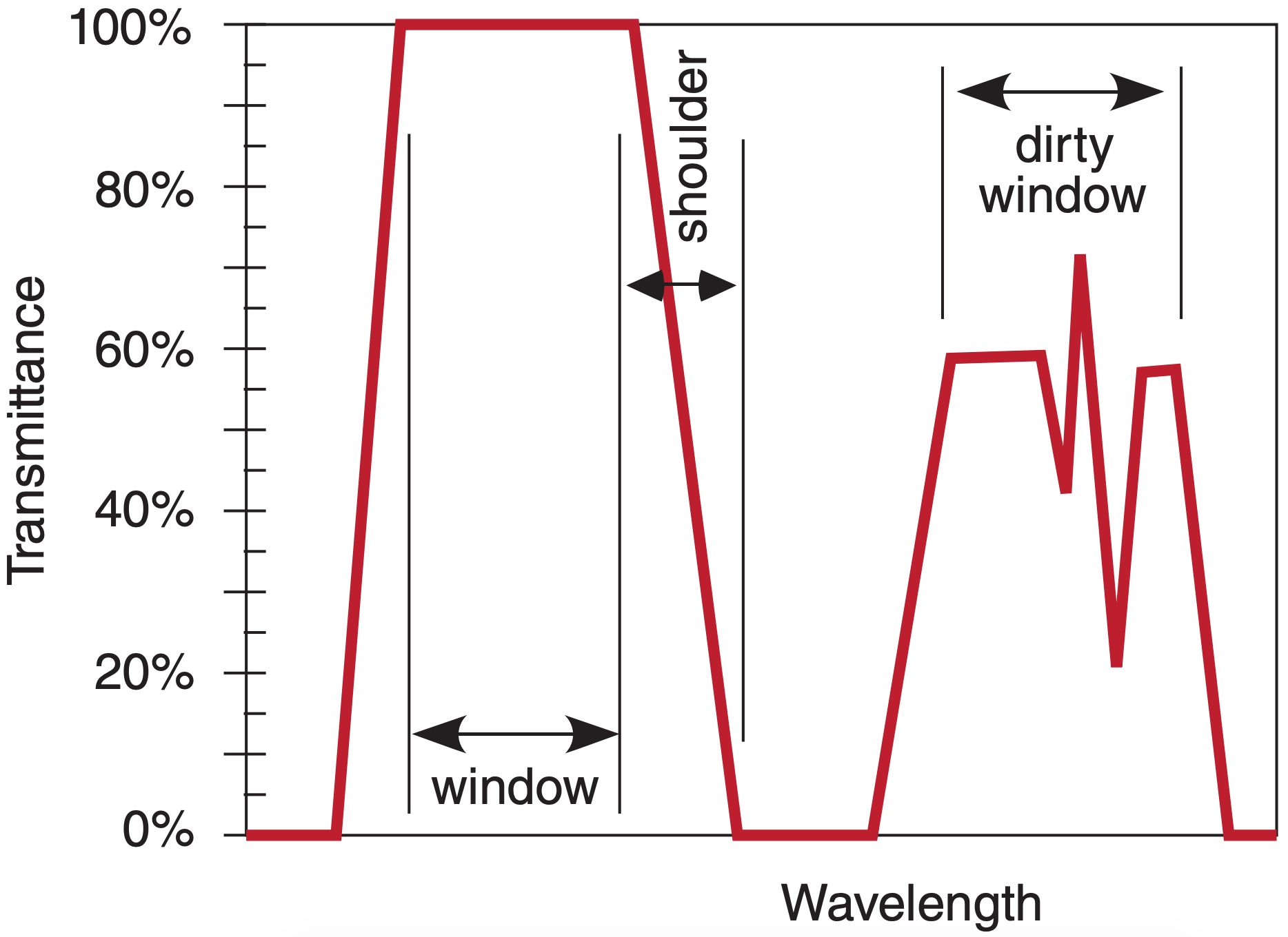
Portions of the spectrum where transmittances are large are called windows (Fig. 8.3), by analogy to visible light passing through clear glass windows. At wavelengths near the window, there can be shoulder regions where transmittance rapidly changes. Portions of the spectrum having partial transmittance are sometimes called dirty windows. By designing satellite-borne radiometers that are sensitive to different window and non-window wavelengths, you can measure different characteristics of the Earth and atmosphere.
Figures 8.4a-d (next 2 pages) show the transmittance at different wavelengths. Different gases in the atmosphere have different molecular vibration and rotation modes, causing them to absorb at discrete wavelengths called absorption lines. In Fig. 8.4, the windows are regions with transmittance of about 80% or higher.
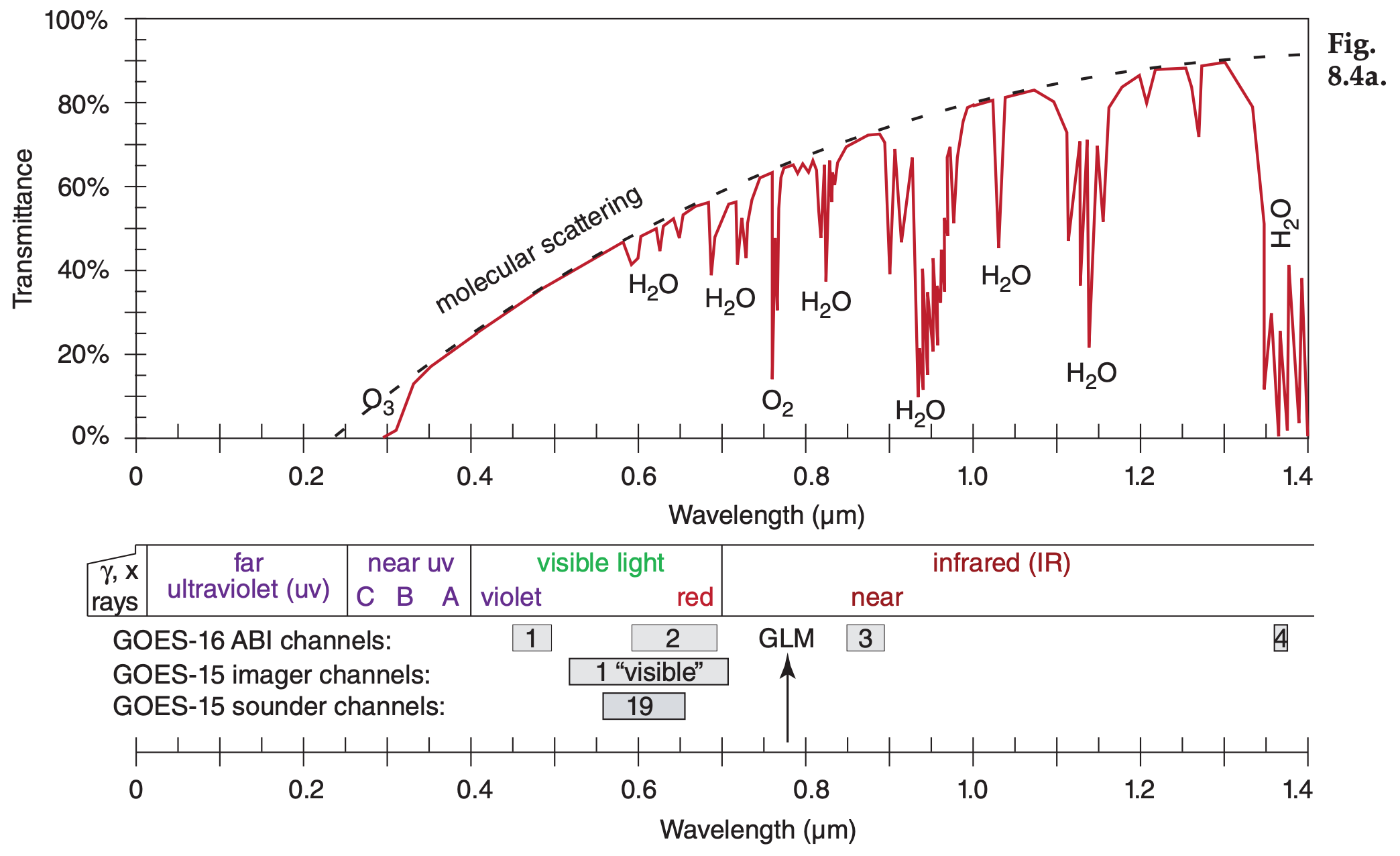
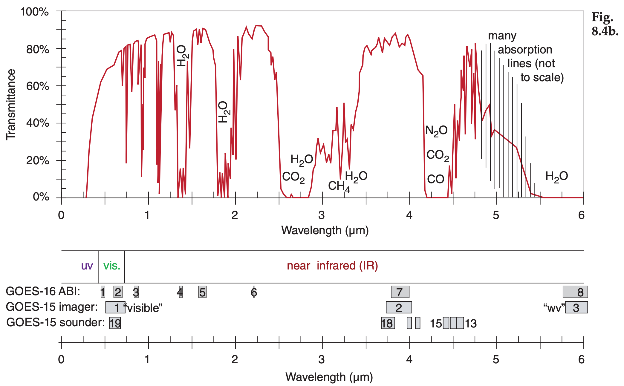
Figure 8.4 (continuation) See Chapter 2 for wavelengths emitted by sun and Earth. Upwelling radiation can be either terrestrial radiation emitted from the atmosphere, ocean and the Earth’s surface, or solar radiation reflected upward from the Earth’s surface and from within the atmosphere. The Geostationary Lightning Mapper (GLM) has an optical transient sensor sensitive to atomic oxygen emissions at 0.7774 µm — effective both day and night (Fig. 8.4a). Note the wavelength unit changes in Fig. 8.4d.
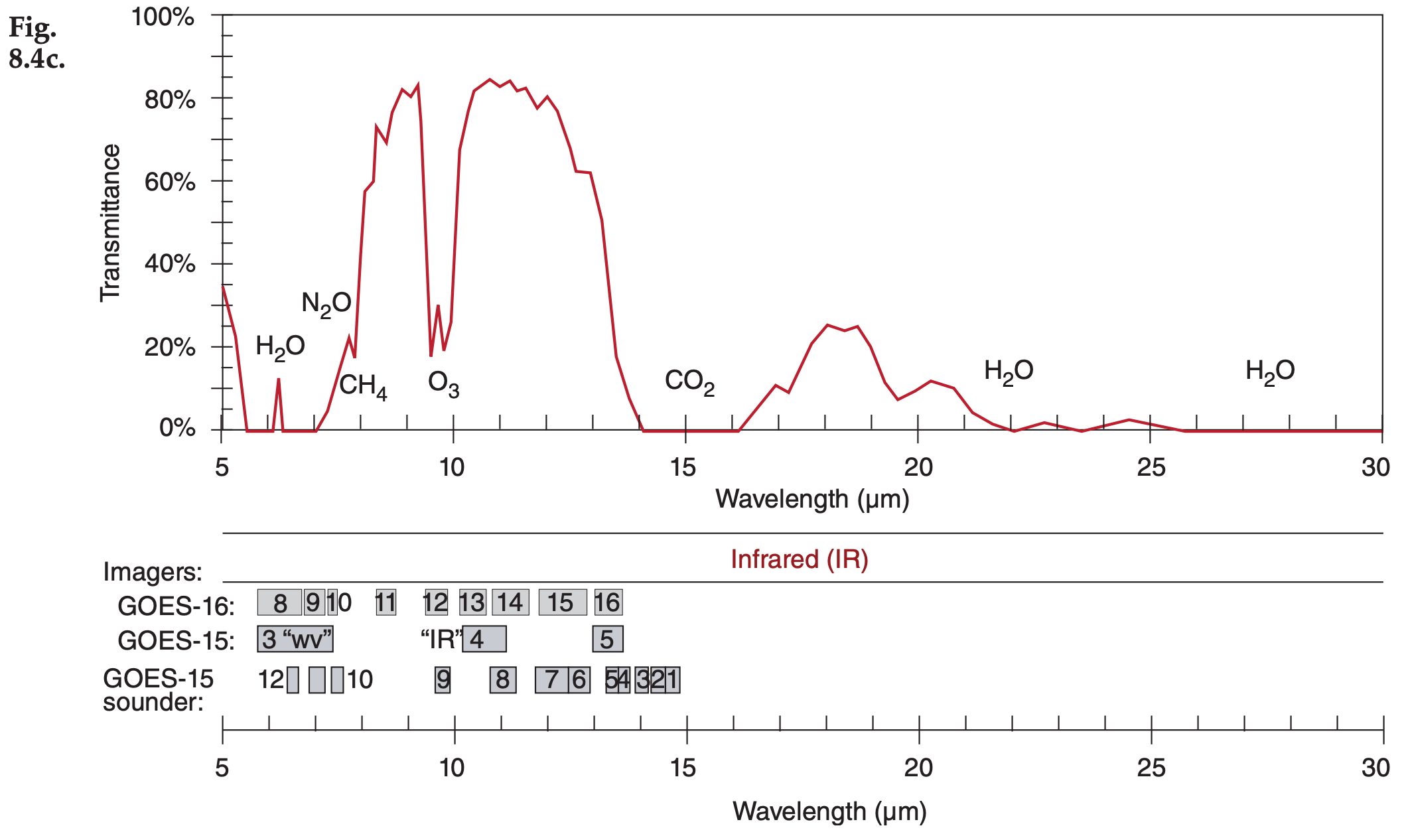
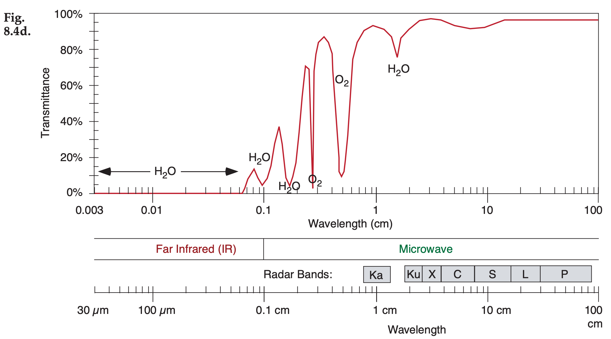
These transmittance curves are not physical laws and are not constant, but can change slightly with atmospheric conditions. The absorption bands (i.e., non-window regions) shift wavelength very slightly with temperature and pressure.
The amount of absorption and transmission depend strongly on the concentration of absorbing gas along the path length of the radiation (see Beer’s Law in the Radiation chapter). Some gas concentrations vary with season (carbon dioxide CO2), some vary hourly depending on the weather (water vapor H2O, ozone O3), while others are relatively constant. Additional gases indicated in these figures are molecular oxygen (O2), methane (CH4), carbon monoxide (CO), and nitrous oxide (N2O).
Water vapor is a major absorber, so more humid conditions and deeper moist layers cause greater absorption. Recall from Chapter 1 that most of our storms and most of the atmosphere’s humidity are trapped within the troposphere. Thus, transmittance of surface emissions is weakest in the tropics (high humidity and deep troposphere) and strongest near the poles (low absolute humidity and shallow troposphere). At mid latitudes, transmittance is greatest in winter (low humidity, shallow troposphere) and weakest in summer (higher humidity and deeper troposphere). Transmittance can easily vary by plus or minus 20% between these different locations and seasons in some portions of the spectrum, especially for wavelengths greater than 5 µm.
Another factor that reduces transmittance is scattering by air molecules and aerosols (e.g., airpollution particles). Scattering increases (causing transmittance to decrease) as wavelength gets shorter (dashed curve in Fig. 8.4a). For cleaner air, the dashed curve is higher and transmittance is greater, but the opposite occurs for heavily polluted, aerosolladen air. The visible light portion of the spectrum is a dirty window region. Fig. 8.4 shows that the atmosphere is clearer in some of the IR windows than in the visible light portion of the spectrum that you see every day with your eyes.
So far, we have examined atmospheric transmittance (the left column of images in Fig. 8.2). Next, we look at atmospheric emissions (right column of Fig. 8.2).
Sample Application
Wavelength 1.85 µm has: (a) what transmittance, and (b) corresponds to which sketch in Fig. 8.2 of Earth visibility as viewed from space?
Find the Answer
Given: λ = 1.85 µm
Find: (a) transmittance = ? % , (b) Earth visibility = ?
(a) From Fig. 8.4b, transmittance = 10% approx., mostly due to strong absorption by water vapor.
(b) It would look like Fig. 8.2b in the infrared.
Check: (no easy check for this)
Exposition: Most water vapor is in the troposphere. Satellites would see it glow like an IR light bulb.
8.1.3. Planck’s Law & Brightness Temperature
In the Radiation chapter, Planck’s law allowed computation of total energy flux radiating from a blackbody object per unit wavelength (W·m–2·µm–1) as a function of temperature. Emissions from a flat surface are in all directions, illuminating a hemisphere around the object.
But a satellite cannot measure the total radiation coming out of the Earth or atmosphere — it can measure only the portion of radiation that happens to be coming toward the satellite within the solid angle intercepted by the radiometer. Assuming the radiation is uniform in all directions (i.e., isotropic), then the portion of radiative flux per unit wavelength λ per unit steradian (sr) of solid angle is Planck’s Law equation divided by π:
\(\ \begin{align} B_{\lambda}(T)=\dfrac{c_{1 B} \cdot \lambda^{-5}}{\exp \left(\dfrac{c_{2}}{\lambda \cdot T}\right)-1}\tag{8.1}\end{align}\)
where B is the blackbody radiance in units of W·m–2·µm–1·sr–1, and
c1B = 1.191 042 82 x 108 W·m–2·µm4·sr–1
c2 = 1.438 775 2 x 104 µm·K .
Thus, c1B = c1/π , where c1 was from eq. (2.13). Don’t forget that T must be in units of Kelvin. A steradian is the solid angle with vertex at the center of a sphere (of radius r) that encompasses an area of r2 on the surface of the sphere; 4π sr cover the whole surface.
Fig. 8.5 shows Planck’s law plotted differently; namely, blackbody radiance vs. temperature. Blackbody radiance increases monotonically with increasing temperature. Hotter objects emit greater radiation (assuming a blackbody emissivity of 1.0).
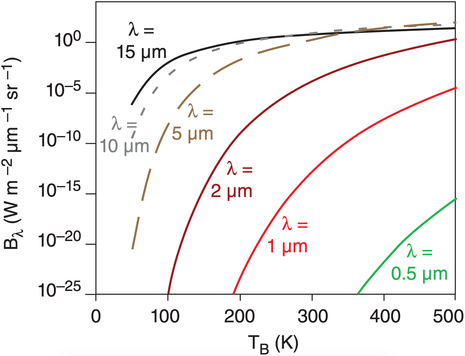
You can also use Planck’s law in reverse. Plug a measured radiance Lλ into eq. (8.1) in place of Bλ, and solve for temperature. This temperature is called the brightness temperature (TB), which is the temperature of a hypothetical blackbody that produces the same radiance as the measured radiance:
\(\ \begin{align} T_{B}=\dfrac{c_{2} / \lambda}{\ln \left(1+\dfrac{c_{1 B} \cdot \lambda^{-5}}{L_{\lambda}}\right)}\tag{8.2}\end{align}\)
Sample Application
What is the blackbody radiance at wavelength 10.9 µm from a cloud top of temperature –20°C ?
Find the Answer
Given: T = –20°C = 253 K, λ = 10.9 µm
Find: Bλ(T) = ? W·m–2·µm–1·sr–1
Use eq. (8.1):
\(\begin{aligned} B_{\lambda}(T) &=\dfrac{\left(1.191 \times 10^{8} \mathrm{W} \cdot \mathrm{m}^{-2} \mu \mathrm{m}^{4} \mathrm{s} \mathrm{r}^{-1}\right) \cdot(10.9 \mu \mathrm{m})^{-5}}{\left[\exp \left(\dfrac{1.44 \times 10^{4} \mu \mathrm{m} \cdot \mathrm{K}}{(10.9 \mu \mathrm{m}) \cdot(253 \mathrm{K})}\right)\right]-1} =4.22 \mathrm{W} \cdot \mathrm{m}^{-2} \cdot \mu \mathrm{m}^{-1} \cdot \mathrm{sr}^{-1} \end{aligned}\)
Check: Units OK. Physics OK.
Exposition: 10.9 µm is an IR wavelength in an atmospheric window region of the spectrum (Fig. 8.4). Thus, these emissions from the cloud would be absorbed very little by the intervening atmosphere, and could be observed by satellite. That is why the “IR” satellite channels are in that spectral band.
Sample Application
A satellite measures a radiance of 1.1 W·m–2·µm–1 ·sr–1 at wavelength 6.7 µm. What is the brightness temperature?
Find the Answer
Given: Lλ(T)= 1.1 W·m–2·µm–1·sr–1, λ = 6.7 µm
Find: TB = ? K
Use eq. (8.2) :
\(\ T_B=\dfrac{(1.44 \times 10^4 \mu m\cdot K)/(6.7 \mu m)}{ln(1+\dfrac{1.191 \times10^8W\cdot m^{-2}\mu m^4 sr^{-1}\cdot(6.7\mu m)^{-5}}{1.1W \cdot m^{-2}\mu m^{-1}sr^{-1}})} =239K=-34^oC\)
Check: Units OK. Physics OK.
Exposition: 6.7 µm is an IR wavelength in a water-vapor absorption (=emission) part of the spectrum (Fig. 8.4). The atmosphere is partly opaque in this region, so the radiation received at the satellite was emitted from the air. This brightness temperature is about –34°C. Such cold temperatures are typically found in the upper troposphere. Thus, we can infer from the standard atmosphere that this satellite channel is “seeing” the upper troposphere.
8.1.4. Radiative Transfer Equation
Recall from Fig. 8.2 that surface emissions might be partially or totally absorbed by the atmosphere before reaching the satellite. The atmosphere emits its own radiation, some of which might also be lost by absorption before reaching the satellite.
These effects are summarized by the radiative transfer equation:
\(\ \begin{align} L_{\lambda}=B_{\lambda}\left(T_{s k i n}\right) \cdot \hat{\tau}_{\lambda, s f c}+\sum_{j=1}^{n} e_{\lambda}\left(z_{j}\right) \cdot B_{\lambda}\left(T_{j}\right) \cdot \hat{\tau}_{\lambda, j}\tag{8.3}\end{align}\)
where Lλ is the radiance at wavelength λ that exits the top of the atmosphere and can be observed by satellite. Tskin is the temperature of the top few molecules of the Earth’s surface, NOT the standard meteorological “surface” temperature measured 2 m above ground. \(\ \hat{τ}\) is transmittance; e is emissivity. This equation is called Schwarzchild’s eq.
The first term on the right hand side (RHS) gives the blackbody emissions from the Earth’s surface, reduced by the overall transmittance \(\hat{\tau}_{ \lambda,\ sfc}\) between the surface and the top of the atmosphere (from Fig. 8.4). Namely, satellites can see the Earth’s surface at wavelengths for which the air is not totally opaque.
The second term on the RHS is a sum over all atmospheric layers ( j = 1 to n), representing the different heights zj in the atmosphere. The net emissions from any one layer j are equal to the emissivity eλ(zj ) of the air at that height for that wavelength times the blackbody emissions. However, the resulting radiance is reduced by the transmittance \(\hat{\tau}_{ \lambda,\ j}\) between that height and the top of the atmosphere.
Transmittance \(\hat{\tau}\) = 0 if all of the radiation is absorbed before reaching the top of the atmosphere. Transmittance = 1 – absorptance; namely, \(\hat{\tau}\) =1 – a.
To help understand the second term, consider a hypothetical or “toy” profile of transmittance (Fig. 8.6). For the air below 5 km altitude, \(\hat{\tau}\) = 0, thus a = (1 – \(\hat{\tau}\) ) = 1. But if a = 1, then e = 1 from Kirchhoff’s Law (see the Radiation chapter). Hence, the layers of air below 5 km are efficient emitters of radiation, but none of this radiation reaches the top of the atmosphere because it is all absorbed by other air molecules along the way, as indicated by zero transmissivity. So a satellite cannot “see” the air at this range of heights.
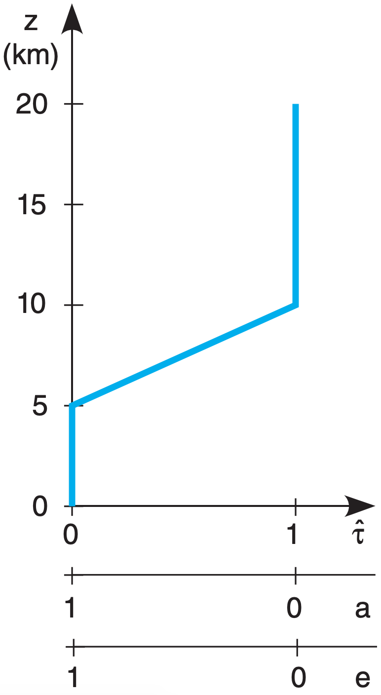
Above 10 km altitude, although the atmosphere is transparent in this toy profile, it has zero emissivity. So no radiation is produced from the air at these altitudes, and again the satellite cannot see this air.
But for heights between 5 and 10 km, the atmosphere is partially emitting (has nonzero emissivity), and the resulting upwelling radiation is not totally absorbed (as indicated by nonzero transmissivity). Thus, radiation from this layer can reach the satellite. The satellite can see through the atmosphere down to this layer, but can’t see air below this layer.
Thus, with the right wavelength, satellites can measure brightness temperature at an elevated layer of cloudless air. At other wavelengths with different transmittance profiles, satellites can measure temperature in different layers, at the top of the atmosphere, at cloud top, or at the Earth’s surface.
In general, heights where transmittance changes are heights for which the air can be remotely observed. After a bit of math, the radiative transfer equation can be rewritten in terms of transmittance change \(\Delta \hat{\tau}=\left[\hat{\tau}_{\text {top of layer } j}-\hat{\tau}_ {\text { bottom of layer } \mathrm{j}}\right]:\)
\(\ \begin{align} L_{\lambda}=B_{\lambda}\left(T_{s k i n}\right) \cdot \hat{\tau}_{\lambda, s f c}+\sum_{j=1}^{n} B_{\lambda}\left(T_{j}\right) \cdot \Delta \hat{\tau}_{\lambda, j}\tag{8.4}\end{align}\)
If the full atmospheric depth is black (i.e., no surface emissions reach outer space), then \(\sum_{j=1}^{n} \Delta \hat{\tau}_{\lambda, j}=1\).
Sample Application
Use the IR transmittance profile of Fig. 8.6, for λ = 6.7 µm. Suppose the vertical temperature profile in the atmosphere is:
| z (km) | T (°C) | 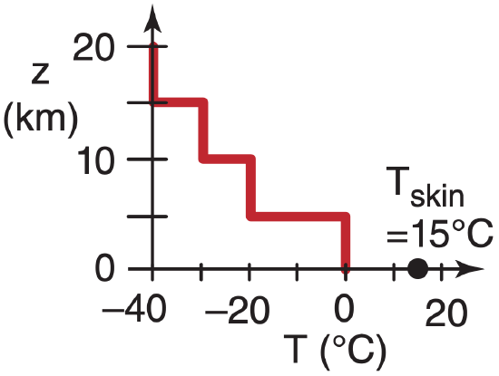 |
| 15 to 20 | –40 | |
| 10 to 15 | –30 | |
| 5 to 10 | –20 | |
| 0 to 5 | 0 |
and the Earth’s surface (skin) temperature is 15°C. Find the upwelling IR radiation at the top of the atmosphere.
Find the Answer
Given: the data above.
Find: Lλ = ? W·m–2·µm–1·sr–1 .
You can save some work by thinking about the problem first. From Fig. 8.6, the transmittance \(\hat{\tau}_{ \lambda,\ s f c}\) is 0 at the surface (z = 0). Thus, none of the surface emissions will reach the top of the atmosphere, so Tskin is irrelevant, and the first term on the RHS of eq. (8.4) is zero.
Also, as discussed, the satellite can’t see the layers between 0 to 5 km and 10 to 20 km for this toy profile, so the temperatures in these layers are also irrelevant. Thus, all terms in the sum in eq. (8.4) are zero except the one term for the one layer at 5 to 10 km.
In this layer, the absolute temperature is T = 273 – 20°C = 253 K. Across this layer, the change of transmittance is \(\Delta \hat{\tau}\) = [ 1 – 0 ]. Thus, the only nonzero part of eq. (8.4) is:
Lλ = 0 + Bλ(253 K) · [ 1 – 0 ]
where you can solve for Bλ using eq. (8.1).
Lλ = Bλ(253 K) = 1.82 W·m–2·µm–1·sr–1 .
Check: Units OK. Physics OK.
Exposition: A lot of work was saved by thinking first.
8.1.5. Weighting Functions
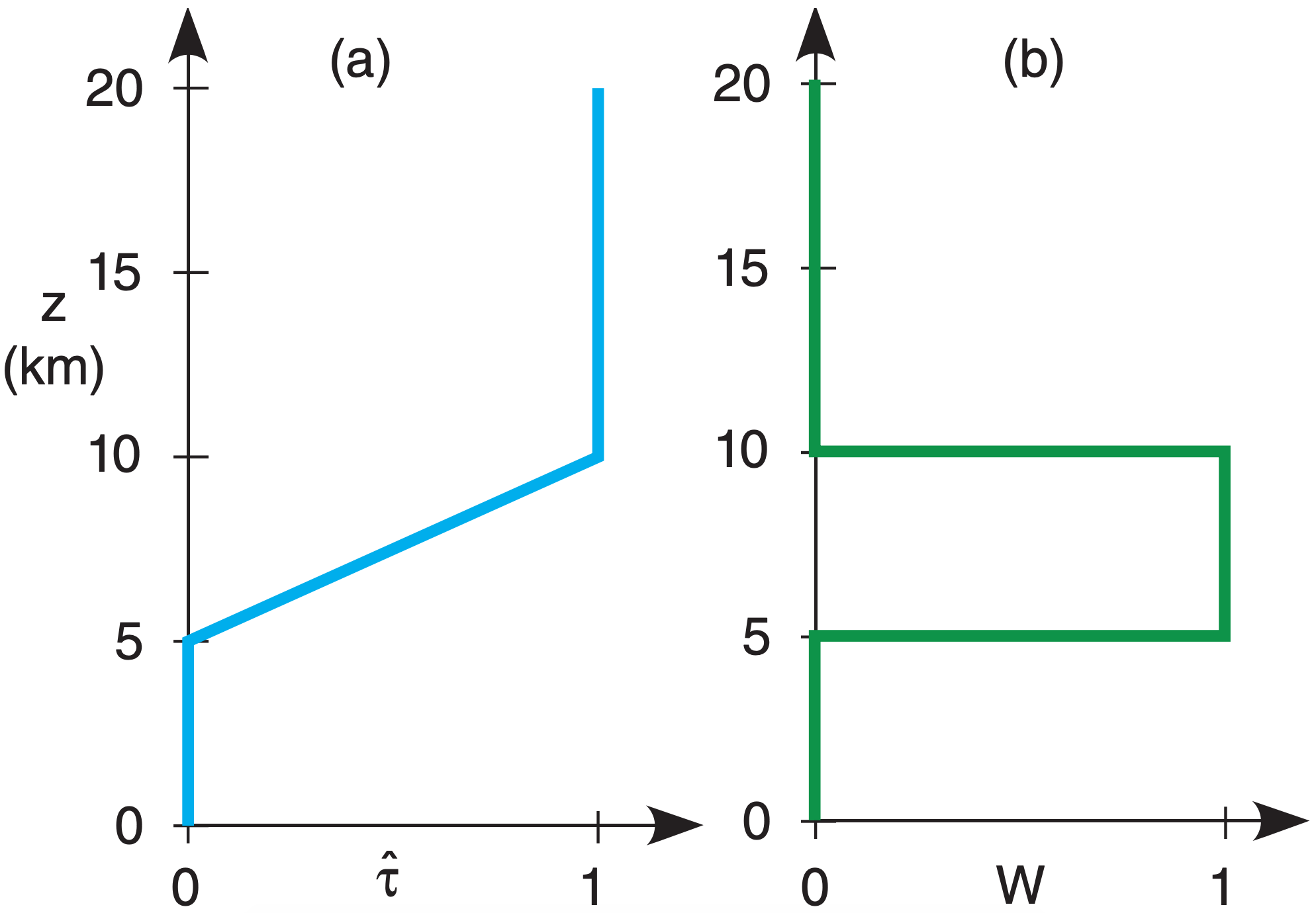
In eq. (8.4) the factor \(\Delta \hat{\tau}\) within the sum acts as a weight that determines the relative contribution of each layer to the total radiance out the top of the atmosphere at that wavelength. Use the symbol Wλ,j for these weights (i.e., \(W_{\lambda, j}=\Delta \hat{\tau}_{\lambda, j}\)). With this trivial notation change, the radiative transfer equation is:
\(\ \begin{align} L_{\lambda}=B_{\lambda}\left(T_{s k i n}\right) \cdot \hat{\tau}_{\lambda, s f c}+\sum_{j=1}^{n} B_{\lambda}\left(T_{j}\right) \cdot W_{\lambda, j}\tag{8.5}\end{align}\)
where Σj Wj = 1 for any one wavelength.
For the toy profile of Fig. 8.7a, the corresponding vertical profile of weights, called the weighting function, is shown in Fig. 8.7b. The weights are proportional to the slope of the transmittance line. (Any vertical line segment in Fig. 8.7a has zero slope, because the independent height variable is along the ordinate in this meteorological graph).
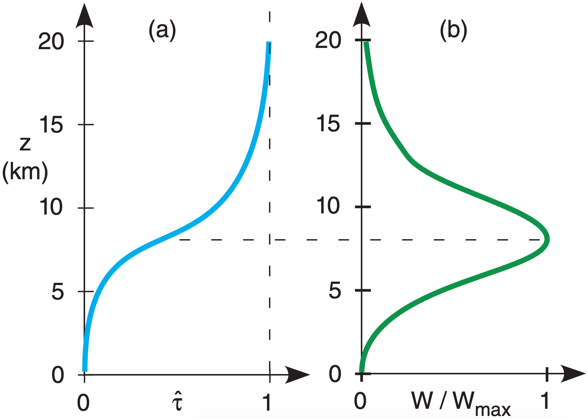
In reality, the weighting function for any wavelength is a smooth curve. Fig. 8.8 shows the curve at λ = 6.7 µm, for which water vapor is the emitter.
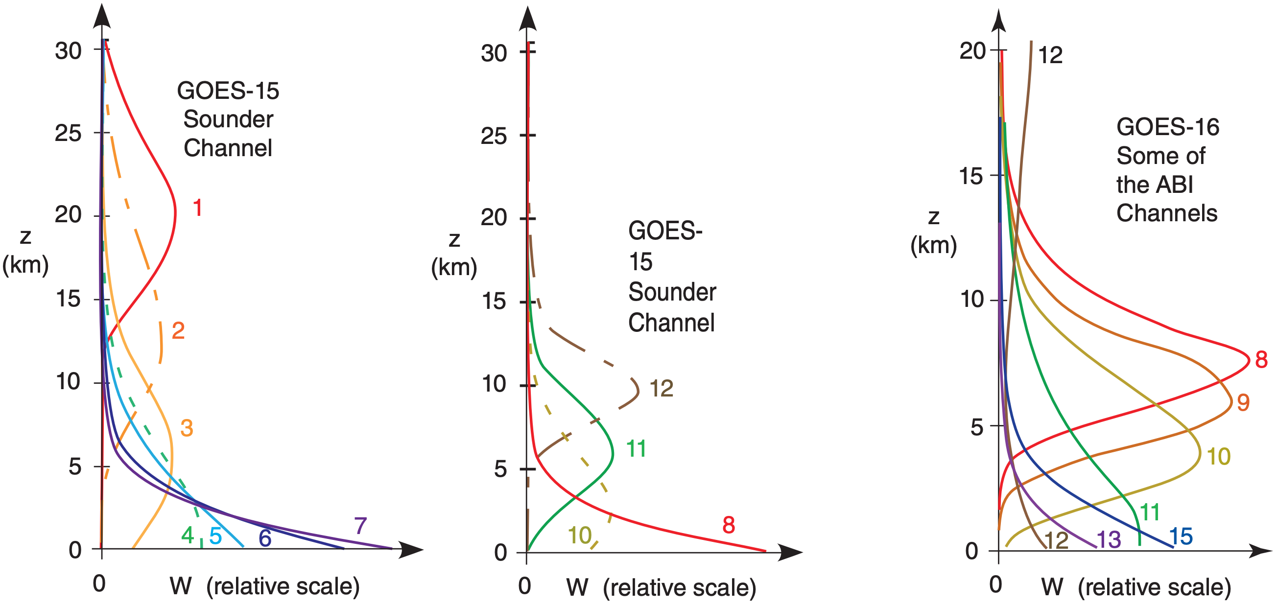
In essence, the weighting function tells you the dominant height range seen by a satellite channel. For Fig. 8.8, all moist layers in the height range of roughly 5 to 12 km (mid to upper troposphere) are blurred together to give one average moisture value. Hence, this water-vapor channel can see tops of deep thunderstorms, but not the boundary layer.
By utilizing many wavelengths with weighting functions that peak at different heights, the satellite can focus on different overlapping height ranges. Heights of peak W vary where \(\hat{\tau}\) in Fig. 8.4 varies with λ. Fig. 8.9 shows the weighting functions for some of the channels (Fig. 8.4) on the GOES satellites. Other satellites can use interferometer methods, giving a nearly infinite suite of weighting functions that peak at a wide range of different altitudes.
