
14.2: The CTSFAF model
- Page ID
- 22672

\( \newcommand{\vecs}[1]{\overset { \scriptstyle \rightharpoonup} {\mathbf{#1}} } \)
\( \newcommand{\vecd}[1]{\overset{-\!-\!\rightharpoonup}{\vphantom{a}\smash {#1}}} \)
\( \newcommand{\dsum}{\displaystyle\sum\limits} \)
\( \newcommand{\dint}{\displaystyle\int\limits} \)
\( \newcommand{\dlim}{\displaystyle\lim\limits} \)
\( \newcommand{\id}{\mathrm{id}}\) \( \newcommand{\Span}{\mathrm{span}}\)
( \newcommand{\kernel}{\mathrm{null}\,}\) \( \newcommand{\range}{\mathrm{range}\,}\)
\( \newcommand{\RealPart}{\mathrm{Re}}\) \( \newcommand{\ImaginaryPart}{\mathrm{Im}}\)
\( \newcommand{\Argument}{\mathrm{Arg}}\) \( \newcommand{\norm}[1]{\| #1 \|}\)
\( \newcommand{\inner}[2]{\langle #1, #2 \rangle}\)
\( \newcommand{\Span}{\mathrm{span}}\)
\( \newcommand{\id}{\mathrm{id}}\)
\( \newcommand{\Span}{\mathrm{span}}\)
\( \newcommand{\kernel}{\mathrm{null}\,}\)
\( \newcommand{\range}{\mathrm{range}\,}\)
\( \newcommand{\RealPart}{\mathrm{Re}}\)
\( \newcommand{\ImaginaryPart}{\mathrm{Im}}\)
\( \newcommand{\Argument}{\mathrm{Arg}}\)
\( \newcommand{\norm}[1]{\| #1 \|}\)
\( \newcommand{\inner}[2]{\langle #1, #2 \rangle}\)
\( \newcommand{\Span}{\mathrm{span}}\) \( \newcommand{\AA}{\unicode[.8,0]{x212B}}\)
\( \newcommand{\vectorA}[1]{\vec{#1}} % arrow\)
\( \newcommand{\vectorAt}[1]{\vec{\text{#1}}} % arrow\)
\( \newcommand{\vectorB}[1]{\overset { \scriptstyle \rightharpoonup} {\mathbf{#1}} } \)
\( \newcommand{\vectorC}[1]{\textbf{#1}} \)
\( \newcommand{\vectorD}[1]{\overrightarrow{#1}} \)
\( \newcommand{\vectorDt}[1]{\overrightarrow{\text{#1}}} \)
\( \newcommand{\vectE}[1]{\overset{-\!-\!\rightharpoonup}{\vphantom{a}\smash{\mathbf {#1}}}} \)
\( \newcommand{\vecs}[1]{\overset { \scriptstyle \rightharpoonup} {\mathbf{#1}} } \)
\(\newcommand{\longvect}{\overrightarrow}\)
\( \newcommand{\vecd}[1]{\overset{-\!-\!\rightharpoonup}{\vphantom{a}\smash {#1}}} \)
\(\newcommand{\avec}{\mathbf a}\) \(\newcommand{\bvec}{\mathbf b}\) \(\newcommand{\cvec}{\mathbf c}\) \(\newcommand{\dvec}{\mathbf d}\) \(\newcommand{\dtil}{\widetilde{\mathbf d}}\) \(\newcommand{\evec}{\mathbf e}\) \(\newcommand{\fvec}{\mathbf f}\) \(\newcommand{\nvec}{\mathbf n}\) \(\newcommand{\pvec}{\mathbf p}\) \(\newcommand{\qvec}{\mathbf q}\) \(\newcommand{\svec}{\mathbf s}\) \(\newcommand{\tvec}{\mathbf t}\) \(\newcommand{\uvec}{\mathbf u}\) \(\newcommand{\vvec}{\mathbf v}\) \(\newcommand{\wvec}{\mathbf w}\) \(\newcommand{\xvec}{\mathbf x}\) \(\newcommand{\yvec}{\mathbf y}\) \(\newcommand{\zvec}{\mathbf z}\) \(\newcommand{\rvec}{\mathbf r}\) \(\newcommand{\mvec}{\mathbf m}\) \(\newcommand{\zerovec}{\mathbf 0}\) \(\newcommand{\onevec}{\mathbf 1}\) \(\newcommand{\real}{\mathbb R}\) \(\newcommand{\twovec}[2]{\left[\begin{array}{r}#1 \\ #2 \end{array}\right]}\) \(\newcommand{\ctwovec}[2]{\left[\begin{array}{c}#1 \\ #2 \end{array}\right]}\) \(\newcommand{\threevec}[3]{\left[\begin{array}{r}#1 \\ #2 \\ #3 \end{array}\right]}\) \(\newcommand{\cthreevec}[3]{\left[\begin{array}{c}#1 \\ #2 \\ #3 \end{array}\right]}\) \(\newcommand{\fourvec}[4]{\left[\begin{array}{r}#1 \\ #2 \\ #3 \\ #4 \end{array}\right]}\) \(\newcommand{\cfourvec}[4]{\left[\begin{array}{c}#1 \\ #2 \\ #3 \\ #4 \end{array}\right]}\) \(\newcommand{\fivevec}[5]{\left[\begin{array}{r}#1 \\ #2 \\ #3 \\ #4 \\ #5 \\ \end{array}\right]}\) \(\newcommand{\cfivevec}[5]{\left[\begin{array}{c}#1 \\ #2 \\ #3 \\ #4 \\ #5 \\ \end{array}\right]}\) \(\newcommand{\mattwo}[4]{\left[\begin{array}{rr}#1 \amp #2 \\ #3 \amp #4 \\ \end{array}\right]}\) \(\newcommand{\laspan}[1]{\text{Span}\{#1\}}\) \(\newcommand{\bcal}{\cal B}\) \(\newcommand{\ccal}{\cal C}\) \(\newcommand{\scal}{\cal S}\) \(\newcommand{\wcal}{\cal W}\) \(\newcommand{\ecal}{\cal E}\) \(\newcommand{\coords}[2]{\left\{#1\right\}_{#2}}\) \(\newcommand{\gray}[1]{\color{gray}{#1}}\) \(\newcommand{\lgray}[1]{\color{lightgray}{#1}}\) \(\newcommand{\rank}{\operatorname{rank}}\) \(\newcommand{\row}{\text{Row}}\) \(\newcommand{\col}{\text{Col}}\) \(\renewcommand{\row}{\text{Row}}\) \(\newcommand{\nul}{\text{Nul}}\) \(\newcommand{\var}{\text{Var}}\) \(\newcommand{\corr}{\text{corr}}\) \(\newcommand{\len}[1]{\left|#1\right|}\) \(\newcommand{\bbar}{\overline{\bvec}}\) \(\newcommand{\bhat}{\widehat{\bvec}}\) \(\newcommand{\bperp}{\bvec^\perp}\) \(\newcommand{\xhat}{\widehat{\xvec}}\) \(\newcommand{\vhat}{\widehat{\vvec}}\) \(\newcommand{\uhat}{\widehat{\uvec}}\) \(\newcommand{\what}{\widehat{\wvec}}\) \(\newcommand{\Sighat}{\widehat{\Sigma}}\) \(\newcommand{\lt}{<}\) \(\newcommand{\gt}{>}\) \(\newcommand{\amp}{&}\) \(\definecolor{fillinmathshade}{gray}{0.9}\)One model for describing sedimentary facies in the lab or the field is the CTSFAF model. This model uses readily observable characteristics of the rocks and aids in the interpretation of depositional environments. The six aspects of CTSFAF are color/composition, texture, sedimentary structures, fossils, association, and form which are described in more detail below.
| Characteristic | Description | Spatial scale of observation |
|---|---|---|
| C: color and composition | Grain colors and % mineral composition | Hand sample, microscope |
| T: texture | Grain size, shape, and sorting | Hand sample, microscope |
| S: sedimentary structures | Depositional/erosion features | Outcrop, hand sample |
| F: fossils | Fossil diversity and abundance | Outcrop, hand sample, microscope |
| A: association | Geologic contacts of beds | Outcrop |
| F: form | Bedding pattern | Outcrop |
Color and composition
Color

The color of a sedimentary rock is typically derived from the minerals that make up the grains within the rock. For clastic sedimentary rocks, the cement holding the grains together may also significantly contribute to the color of the rock. For example, many of the gorgeous red and orange sandstones from the American Southwest are quartz sand cemented with hematite, a rust-colored iron oxide. Some sedimentary rocks can have a different color in a weathered state, thus when observing sedimentary rocks in the field, it is important to always conduct observations on a freshly broken surface of the rock.
Sedimentary rock composition
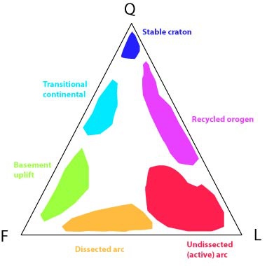
Broadly, sedimentary rocks can be classified as clastic, biochemical, or chemical. In the context of facies, it is helpful to think about clastic and biochemical sedimentary rocks as either siliciclastic or carbonate. Siliciclastic rocks are those that are made from weathered grains of pre-existing rocks made of predominantly silicate minerals. For rocks with gravel or sand-sized grains (breccia, conglomerate, sandstones) noting percentages of quartz, feldspar, and lithic fragments (pieces of rock) in the rock (QFL), clues about tectonic history can be determined. High quartz percentages suggest tectonic stability or extensive reworking of sediments as the more chemically and less physically resistant minerals have eroded away. Lots of feldspar indicates immature sediments that have recently been produced via basement uplift of continental crust (i.e., thick-skinned deformation including cratonic rifting), since otherwise feldspar quickly weathers to clay minerals. Lithic fragments are indicative of volcanic activity and/or shallow tectonic activity (i.e., thin-skinned deformation) and also indicate immature sediment. QFL ternary diagrams can be used to classify these rocks. Siltstones, claystones, and shales are composed of the weathering products of silicate minerals.
Carbonate rocks are named such because they are made of minerals with a carbonate \(\ce{(CO3)^{-2}}\) anion: usually calcite (which makes limestones) or dolomite (which makes dolostone). While there are some limestones that form in lake or hot spring environments on land, most limestones are associated with marine depositional environments, including epicontinental seas, continental shelves and slopes, and the abyssal plains. These limestones are made from clasts derived from skeletal elements (shells) or fecal pellets of organisms (peloids), chemically precipitated grains (ooids), or pieces of other carbonate material (rip-up clasts, clay-sized particles).
The Dunham classification system for carbonate rocks is useful to describe carbonates in the field and in hand samples. It compares the amount of clasts to the amount of clay-sized particles within a sample, and is analogous to the classification scheme for siliciclastic sedimentary rocks. Grain-supported grainstones and packstones have more clasts, while wackestones and mudstones have more fine grains.
Another classification system for carbonates, the Folk system, focuses on the type of clasts (allochems) and the character of binding (interstitial) material. This system is particularly useful when describing carbonates in microscopic thin section.
Texture
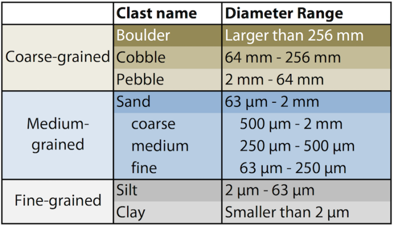
When describing sedimentary texture, three aspects must be detailed: grain size, shape, and sorting. All of these factors are dependent on the distance sediment has been transported from its source, where it was originally weathered from bedrock. As sediment is transported by currents from source to depositional environment, it becomes smaller, rounder, and more well-sorted.

Sedimentary structures

Sedimentary structures are valuable indicators for determinations of current energy, direction of flow, intervals of wetting and drying and many other subtle aspects of depositional environments. Examples include mudcracks, ripples, cross-beds, tool marks, laminations, and more. See this page for detailed discussion and examples of sedimentary structures.
Fossils

The fossil content of a sedimentary bed can provide key information regarding the depositional environment in which the layer formed. As with the sediments, observations can be made at multiple spatial scales: microscopic, hand sample, and outcrop. Both diversity and abundance should be recorded. Diversity includes a list of all types of fossils found within the sample or outcrop. Abundances can record actual counts of fossil occurrences, or relative occurrences (e.g., rare, common, abundant). Within a hand sample, qualities of fossil preservation (taphonomy) should be noted.
At an outcrop level, it is useful to consider the distribution of fossil content within individual beds to reveal any patchiness, or spatial variability, within the environment. Vertical stratigraphic changes in fossil content should also be recorded as the fossils can reveal both significant or subtle changes in water depth, temperature, salinity, and sedimentation rates.
Association
One important feature of strata at the outcrop level is how sedimentary layers, or strata, come into contact with one another. The place where one rock type touches another is known as geologic contact. Sedimentary layers exhibit depositional contacts. The contact is described as conformable when the layers pile atop one another in succession–they “conform” to expectation. Alternatively, if there is an unconformity present between layers then the contacts are unconformable. Remember an unconformity means there are missing layers due to nondeposition or erosion. Other types of geologic contacts include fault contacts where different rock layers touch on opposite sides of a fault, and intrusive contacts, where there is commonly contact metamorphism as an igneous intrusion of magma comes into contact with surrounding country rock.
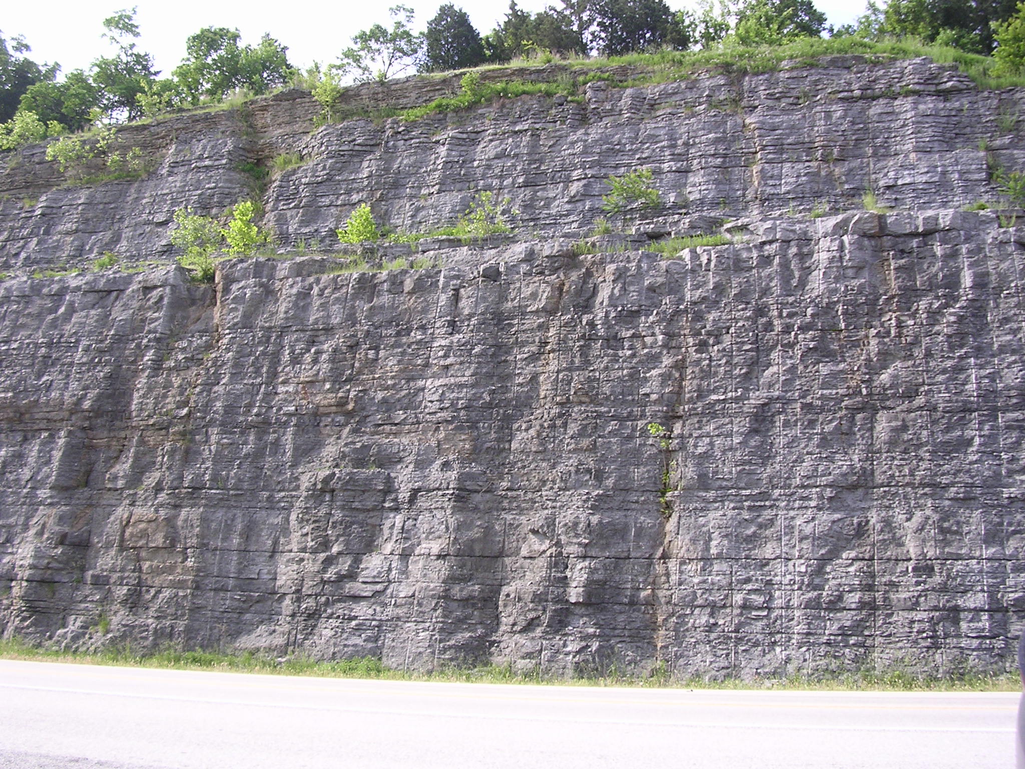
Form

At an outcrop level, the form of a sedimentary bed can be observed. In some cases, individual layers may maintain their thickness across the entire outcrop, creating tabular, or parallel, beds. This type of bedding is common when sediment supplies are constant and the depositional environment is laterally pervasive. Other times, a sedimentary layer may pinch out, thinning to the point of disappearing from the stratigraphic section, creating a discontinuous bed. This is often seen in fan-shaped structures that develop in alluvial fans, deltas, and submarine fans. In some cases, a layer may pinch out in both directions, creating a lenticular bed. This is common for channel sandstones in river or deltaic systems.