
1.2: Radiometric measurements
- Page ID
- 17273

\( \newcommand{\vecs}[1]{\overset { \scriptstyle \rightharpoonup} {\mathbf{#1}} } \)
\( \newcommand{\vecd}[1]{\overset{-\!-\!\rightharpoonup}{\vphantom{a}\smash {#1}}} \)
\( \newcommand{\dsum}{\displaystyle\sum\limits} \)
\( \newcommand{\dint}{\displaystyle\int\limits} \)
\( \newcommand{\dlim}{\displaystyle\lim\limits} \)
\( \newcommand{\id}{\mathrm{id}}\) \( \newcommand{\Span}{\mathrm{span}}\)
( \newcommand{\kernel}{\mathrm{null}\,}\) \( \newcommand{\range}{\mathrm{range}\,}\)
\( \newcommand{\RealPart}{\mathrm{Re}}\) \( \newcommand{\ImaginaryPart}{\mathrm{Im}}\)
\( \newcommand{\Argument}{\mathrm{Arg}}\) \( \newcommand{\norm}[1]{\| #1 \|}\)
\( \newcommand{\inner}[2]{\langle #1, #2 \rangle}\)
\( \newcommand{\Span}{\mathrm{span}}\)
\( \newcommand{\id}{\mathrm{id}}\)
\( \newcommand{\Span}{\mathrm{span}}\)
\( \newcommand{\kernel}{\mathrm{null}\,}\)
\( \newcommand{\range}{\mathrm{range}\,}\)
\( \newcommand{\RealPart}{\mathrm{Re}}\)
\( \newcommand{\ImaginaryPart}{\mathrm{Im}}\)
\( \newcommand{\Argument}{\mathrm{Arg}}\)
\( \newcommand{\norm}[1]{\| #1 \|}\)
\( \newcommand{\inner}[2]{\langle #1, #2 \rangle}\)
\( \newcommand{\Span}{\mathrm{span}}\) \( \newcommand{\AA}{\unicode[.8,0]{x212B}}\)
\( \newcommand{\vectorA}[1]{\vec{#1}} % arrow\)
\( \newcommand{\vectorAt}[1]{\vec{\text{#1}}} % arrow\)
\( \newcommand{\vectorB}[1]{\overset { \scriptstyle \rightharpoonup} {\mathbf{#1}} } \)
\( \newcommand{\vectorC}[1]{\textbf{#1}} \)
\( \newcommand{\vectorD}[1]{\overrightarrow{#1}} \)
\( \newcommand{\vectorDt}[1]{\overrightarrow{\text{#1}}} \)
\( \newcommand{\vectE}[1]{\overset{-\!-\!\rightharpoonup}{\vphantom{a}\smash{\mathbf {#1}}}} \)
\( \newcommand{\vecs}[1]{\overset { \scriptstyle \rightharpoonup} {\mathbf{#1}} } \)
\(\newcommand{\longvect}{\overrightarrow}\)
\( \newcommand{\vecd}[1]{\overset{-\!-\!\rightharpoonup}{\vphantom{a}\smash {#1}}} \)
\(\newcommand{\avec}{\mathbf a}\) \(\newcommand{\bvec}{\mathbf b}\) \(\newcommand{\cvec}{\mathbf c}\) \(\newcommand{\dvec}{\mathbf d}\) \(\newcommand{\dtil}{\widetilde{\mathbf d}}\) \(\newcommand{\evec}{\mathbf e}\) \(\newcommand{\fvec}{\mathbf f}\) \(\newcommand{\nvec}{\mathbf n}\) \(\newcommand{\pvec}{\mathbf p}\) \(\newcommand{\qvec}{\mathbf q}\) \(\newcommand{\svec}{\mathbf s}\) \(\newcommand{\tvec}{\mathbf t}\) \(\newcommand{\uvec}{\mathbf u}\) \(\newcommand{\vvec}{\mathbf v}\) \(\newcommand{\wvec}{\mathbf w}\) \(\newcommand{\xvec}{\mathbf x}\) \(\newcommand{\yvec}{\mathbf y}\) \(\newcommand{\zvec}{\mathbf z}\) \(\newcommand{\rvec}{\mathbf r}\) \(\newcommand{\mvec}{\mathbf m}\) \(\newcommand{\zerovec}{\mathbf 0}\) \(\newcommand{\onevec}{\mathbf 1}\) \(\newcommand{\real}{\mathbb R}\) \(\newcommand{\twovec}[2]{\left[\begin{array}{r}#1 \\ #2 \end{array}\right]}\) \(\newcommand{\ctwovec}[2]{\left[\begin{array}{c}#1 \\ #2 \end{array}\right]}\) \(\newcommand{\threevec}[3]{\left[\begin{array}{r}#1 \\ #2 \\ #3 \end{array}\right]}\) \(\newcommand{\cthreevec}[3]{\left[\begin{array}{c}#1 \\ #2 \\ #3 \end{array}\right]}\) \(\newcommand{\fourvec}[4]{\left[\begin{array}{r}#1 \\ #2 \\ #3 \\ #4 \end{array}\right]}\) \(\newcommand{\cfourvec}[4]{\left[\begin{array}{c}#1 \\ #2 \\ #3 \\ #4 \end{array}\right]}\) \(\newcommand{\fivevec}[5]{\left[\begin{array}{r}#1 \\ #2 \\ #3 \\ #4 \\ #5 \\ \end{array}\right]}\) \(\newcommand{\cfivevec}[5]{\left[\begin{array}{c}#1 \\ #2 \\ #3 \\ #4 \\ #5 \\ \end{array}\right]}\) \(\newcommand{\mattwo}[4]{\left[\begin{array}{rr}#1 \amp #2 \\ #3 \amp #4 \\ \end{array}\right]}\) \(\newcommand{\laspan}[1]{\text{Span}\{#1\}}\) \(\newcommand{\bcal}{\cal B}\) \(\newcommand{\ccal}{\cal C}\) \(\newcommand{\scal}{\cal S}\) \(\newcommand{\wcal}{\cal W}\) \(\newcommand{\ecal}{\cal E}\) \(\newcommand{\coords}[2]{\left\{#1\right\}_{#2}}\) \(\newcommand{\gray}[1]{\color{gray}{#1}}\) \(\newcommand{\lgray}[1]{\color{lightgray}{#1}}\) \(\newcommand{\rank}{\operatorname{rank}}\) \(\newcommand{\row}{\text{Row}}\) \(\newcommand{\col}{\text{Col}}\) \(\renewcommand{\row}{\text{Row}}\) \(\newcommand{\nul}{\text{Nul}}\) \(\newcommand{\var}{\text{Var}}\) \(\newcommand{\corr}{\text{corr}}\) \(\newcommand{\len}[1]{\left|#1\right|}\) \(\newcommand{\bbar}{\overline{\bvec}}\) \(\newcommand{\bhat}{\widehat{\bvec}}\) \(\newcommand{\bperp}{\bvec^\perp}\) \(\newcommand{\xhat}{\widehat{\xvec}}\) \(\newcommand{\vhat}{\widehat{\vvec}}\) \(\newcommand{\uhat}{\widehat{\uvec}}\) \(\newcommand{\what}{\widehat{\wvec}}\) \(\newcommand{\Sighat}{\widehat{\Sigma}}\) \(\newcommand{\lt}{<}\) \(\newcommand{\gt}{>}\) \(\newcommand{\amp}{&}\) \(\definecolor{fillinmathshade}{gray}{0.9}\)2
While much remote sensing data can be visualized as imagery, and interpreted directly as such to locate e.g. cities and ships and fires, it is important to understand that most satellite sensors can also be thought of as precisely calibrated instruments used to measure the characteristics of electromagnetic radiation that arrives from a given direction at the time of measurement. In this chapter we will focus on such use of satellite imagery. First we need to define some concepts related to electromagnetic radiation and how it is measured. After that we will look at how to employ those concepts to extract useful information from satellite imagery.
Concepts related to EMR intensity
Several other properties of EMR fields relate to their intensity – the amount of energy contained in them. The fundamental SI unit of energy is the Joule (J). Because radiation moves as the EMR waves propagate, an important measure of the intensity of an EMR field is the amount of energy moving onto, through or from a surface or volume per unit time. This is called radiant flux, and is measured in Joules per second, or Watts (W). In remote sensing, we are almost always interested in measuring the intensity of radiation over a finite area (e.g. one represented by a pixel in a satellite image). This is called the radiant flux density, and is measured as radiant flux per unit area, for example W m-2. For practical use, the term irradiance is used to describe radiant flux density incident upon a surface, and exitance is used to describe radiant flux density leaving a surface (Figure 13).
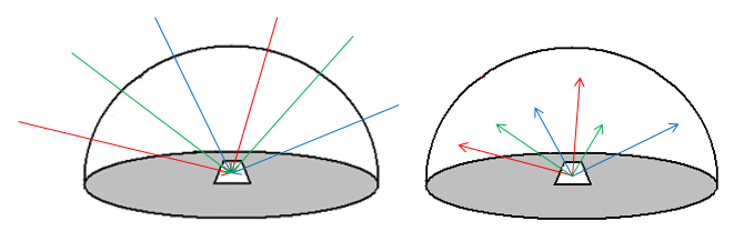
13: Irradiance and Exitance. On the left, irradiance is the radiant flux incident on a surface per unit area. On the right, exitance is the radiant flux leaving a surface per unit area. Both are typically measured in W m-2. The arrows of different colour indicate that these two radiant flux densities are measured for all wavelengths present in the radiation field. By Anders Knudby, CC BY 4.0.
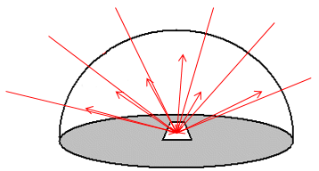
While irradiance and exitance are useful concepts, we cannot measure them with instruments on flying platforms because they encompass radiation incident upon or leaving a surface in any direction. In other words, to measure exitance for a 1 m2 part of the Earth’s surface, we would need to place a hemispherical sensor over the area in question, thus measuring the outgoing radiation in all upward directions (if measuring sunlight reflected from the surface, shading by the instrument would obviously make the measurement useless). Another unit of EMR intensity commonly used in remote sensing is therefore something more closely related to what is actually measured by instruments, it is called radiance and is defined as the radiant flux density per unit of projected source area, in a particular direction defined by a solid angle (Figure 14). A solid angle can be thought of as a cone – in most remote sensing cases this cone is incredibly narrow as it stretches from the observed area to the relevant detecting element in the sensor.
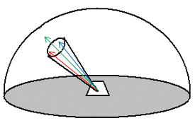
14: Radiance. Compared to irradiance and exitance, radiance is calculated per unit of projected surface area, and within a specified solid angle. Radiance is typically measured with units of W m-2 sr-1, where sr stands for steradian, which is a measure of solid angle. By Anders Knudby, CC BY 4.0.
When measuring EMR with instruments on aircraft or satellites, measurements of radiance are usually made for discrete intervals of wavelengths. For example, ‘Band 1’ on many satellites has been designed to measure only the radiance of electromagnetic radiation with certain wavelengths that appear blue to human eyes, such as between 420 and 470 nm. Assuming that this range of wavelengths are all measured perfectly by ‘Band 1’, we can find the spectralradiance by dividing the radiance measured by the range of wavelengths measured (in this case 50 nm). The spectral radiance is a very commonly used measure in remote sensing, and is often directly related to the raw values (i.e. Digital Numbers) found in each band in remote sensing images.
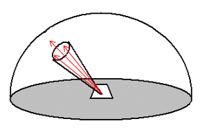
While spectral radiance is the unit of EMR intensity that is most closely related to what is actually measured by remote sensing instruments, it has the unfortunate quality of being dependent on the illumination of the observed area. This is obvious if you imagine measuring the amount of light coming off your local neighbourhood parking lot. During a sunny day, lots of light comes off the asphalt surface, sometimes to the extent that you need to squint to look at it. In other words, the surface has a high spectral radiance in the visible wavelengths. On an overcast day, less light comes off the surface – lower spectral radiance. And during the night, obviously, very little light comes off the surface – very low spectral radiance. Measuring the spectral radiance coming off a surface thus cannot directly tell us much about what that surface is – whether it is a parking lot or a lake or a forest. The thing we would prefer to measure instead is the reflectance of a surface – the amount of radiation it reflects per unit of radiation incident upon it. This is a real physical property of a material that is in most cases completely independent of illumination, and therefore something that can be used to identify the material. A high reflectance is what makes white surfaces white, and a low reflectance is what makes black surfaces black. A commonly used kind of reflectance is the albedo, which is what remote sensing people call diffuse reflectance. It is calculated as the exitance divided by the irradiance, and is a unitless measure ranging between 0 (for completely black surfaces that have no exitance) and 1 (for completely white surface that reflect all the radiation incident upon them).
16: Diffuse reflectance. Defined as exitance (outgoing arrows) divided by irradiance (incoming arrows). By Anders Knudby, CC BY 4.0.
Diffuse reflectance cannot be measured directly in remote sensing – in fact neither of the two necessary terms can be measured. However, it can be estimated quite accurately at the top of the atmosphere (more on that later) by employing two tricks. First, we know quite well how much radiation is produced by the Sun at various wavelengths, so we can estimate the irradiance with good accuracy. Second, if we assume that the radiance is a known function of the direction of propagation, then we can convert radiance measured in one direction to exitance. Together, this gives us the information necessary to convert a measurement of radiance to an estimate of diffuse reflectance.
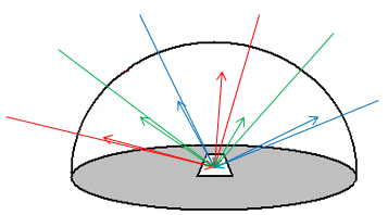
However, we need one last step (for now) to arrive at a measurement that can be used to identify what we are looking at, because diffuse reflectance is a single value that tells us something about how bright a surface is, but it does not tell us anything about its chromacity (which is the aspect of colour that does not include brightness, so for example light red and dark red can have the same chromacity, while light red and light green have different chromacities). However, as outlined above in the paragraph on spectral radiance, measurements made with remote sensing instruments are actually measurements of spectral radiance. We can thus convert these measurements to estimates of spectral exitance, and divide by spectral irradiance, to arrive at a measure of spectral diffuse reflectance. Without accounting for interactions between electromagnetic radiation and the atmosphere, this is as close as we will get to producing a measure that tells us something about what is covering the Earth’s surface in the pixel we measured.
17: Spectral diffuse reflectance. Defined as spectral exitance divided by spectral irradiance. By Anders Knudby, CC BY 4.0.
How electromagnetic radiation is detected and measured
To measure the intensity of incoming electromagnetic radiation, remote sensing instruments rely on special materials that are efficient absorbers of radiation with the desired range of wavelengths, and that generate an electrical current when exposed to radiation – a current which is then measured. While different materials are employed to absorb and thus detect radiation at different wavelengths in different kinds of sensors, the basic principle is well illustrated with passive optical remote sensing instruments, most of which rely on CCD or CMOS sensors, just like the camera in your phone.
Imagine a camera attached to a satellite in space, pointing down on Earth. For a very short period of time, the aperture of the camera is opened, letting in light that has been produced by the Sun (according to Planck’s Law) and reflected by the Earth’s atmosphere and surface back into space, exactly in the direction of the satellite. Inside the camera is a 2-dimensional CCD, a kind of checkerboard with 3 x 3 individual little detecting elements, each of which is capable of absorbing sunlight and thereby producing an electrical current proportional to the intensity of incoming light. Detecting elements exposed to more intense sunlight produce a current with greater voltage, so the voltage is a direct indication of the amount of sunlight each element was exposed to. An example is provided in Table 1.
Table 1: Example of voltages generated by individual detecting elements in a CCD housed in a spaceborne camera. By Anders Knudby, CC BY 4.0.
|
1.2 |
1.1 |
0.9 |
|
1.3 |
1.2 |
1.1 |
|
1.1 |
0.9 |
0.8 |
The optics (system of lenses) in the camera ensure that each individual detecting element is exposed to light coming from a unique pre-defined direction relative to the camera. Knowing where the satellite is and how it is oriented relative to the Earth, each of these directions can be converted to a set of geographic coordinates (latitude/longitude) on the Earth surface, from where the light registered by each detecting element must have been reflected. In other words, the electrical current generated by each of the 3 x 3 detecting elements can be mapped back to a location on the Earth’s surface.
Table 2: Geographic coordinates from which the sunlight producing the electrical current in each element from Table 1 has been reflected. For this example, ignore the fact that the pixel size implicit in the geographic coordinates is not square and very large. By Anders Knudby, CC BY 4.0.
|
45.1 N / 80.5 W |
45.1 N / 80.4 W |
45.1 N / 80.3 W |
|
45.0 N / 80.5 W |
45.0 N / 80.4 W |
45.0 N / 80.3 W |
|
44.9 N / 80.5 W |
44.9 N / 80.4 W |
44.9 N / 80.3 W |
Because the voltage of the electrical current generated by each detecting element is proportional to the radiant flux density of the incoming radiation, with proper calibration the voltage produced by each detecting element can be converted to a measure of incoming radiant flux density at the camera. Furthermore, with knowledge of the distance between the satellite and the Earth’s surface, this can in turn be converted to a measure of the radiance coming from the observed area. And with that we have one of the fundamental measurements in remote sensing – the radiance coming from a well-defined area on the Earth’s surface.
Calibration
In the previous section, it was mentioned that the voltage generated by a detecting element can be converted to radiant flux density or radiance with proper calibration. Such calibration is done for all sensors prior to launch by exposing them to light of varying levels of known radiance, noting down the voltage created by each exposure. From this, a simple conversion equation, typically linear or nearly linear, can be created to convert between voltage and radiance. An example of the kind of setup needed to perform such calibration is shown in Figure 18.
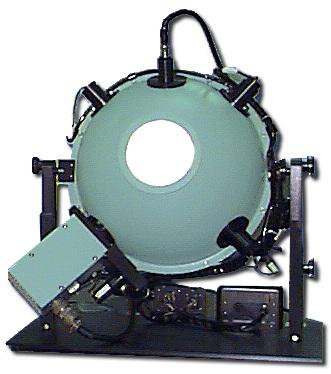
18: Integrating sphere used for sensor calibration. Commercial Integrating Sphere by Electro Optical Industries, Wikimedia Commons, CC BY-SA 3.0.
Multispectral sensing
We have so far ignored the fact that most satellite sensors are designed to detect radiance at multiple distinct ranges of wavelengths, each producing what is known as a ‘Band’. The incoming light field reaching the sensor is in the case of reflected sunlight always a mix of radiation with many different wavelengths, so to separate these out and measure the radiance of distinct ranges of wavelengths individually required an additional step beyond what has been outlined above. Different kinds of technologies are used to perform this step, the simplest of which relies on a beam splitter. A beam splitter can be thought of as a kind of fancy prism that redirects electromagnetic radiation within a defined range of wavelengths in one direction, while letting radiation with other wavelengths move on unimpeded. Multiple individual sensors can then be put in the proper locations in the imaging sensor, with the CCD destined to produce data for the ‘red’ band being located where the beam splitter redirects radiation with wavelengths between 600 and 700 nm (typically considered ‘red’ light), and so on for each individual CCD. Other technologies than beam splitters are in use, each accomplishing the same basic task of allowing radiation with different wavelengths to be registered separately.
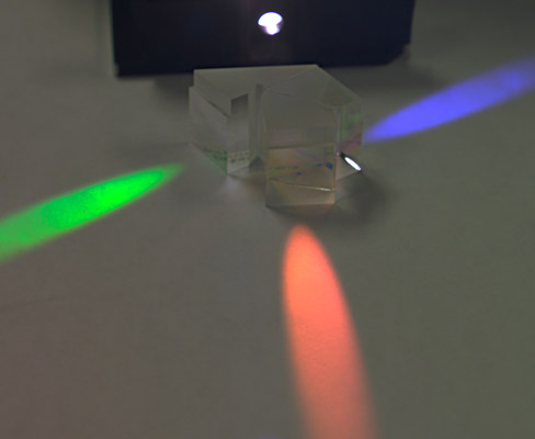
19: The idea of a beam splitter. Radiation enters from the source, and photons are redirected according to their wavelength. Three CCDs can then be positioned to measure the intensity of red, green, and blue light separately. Color Separation Prism by Dick Lyon, Wikimedia Commons, public domain.
Note: For the sake of simplicity, we have used a traditional ‘camera’ as the model to explain how passive optical sensors detect and measure incoming electromagnetic radiation. While traditional frame cameras are still the instrument of choice in the aerial photography industry, and in the growing field of drone-based remote sensing, passive optical sensors onboard satellites take one of two other forms: push-broom or whisk-broom scanners. The details of these detecting systems are beyond the scope of these notes, but basic information is provided here:
- A push-broom scanner is made of a series of one-dimensional CCDs, each typically consisting of several thousands of individual detectors in one row. Each CCD is positioned carefully in the instrument, ‘after’ a beam splitter, to record radiation in what becomes one band, more or less as shown in Figure 19. The instrument does not have a shutter, rather the CCDs record incoming radiation from a very wide and narrow line on the Earth, reaching from one side of the sub-orbital swath to the other. These measurements become one line (row) in a satellite image. As the satellite moves along its orbit, another line is recorded, then another, and another, until thousands of lines have been measured. These are then all put together to form an image.
- A whisk-broom scanner relies on a rotating scan mirror to direct radiation from different parts of the Earth’s surface onto a smaller number of CCDs. The position of the mirror at any given time can be used to calculate the direction from which the measured radiation arrived at the sensor. Such measurements, with corresponding geolocation information, are taken in rapid succession, and ultimately put together as an image.