7.4: The Ekman Spiral
- Page ID
- 4193
\( \newcommand{\vecs}[1]{\overset { \scriptstyle \rightharpoonup} {\mathbf{#1}} } \)
\( \newcommand{\vecd}[1]{\overset{-\!-\!\rightharpoonup}{\vphantom{a}\smash {#1}}} \)
\( \newcommand{\id}{\mathrm{id}}\) \( \newcommand{\Span}{\mathrm{span}}\)
( \newcommand{\kernel}{\mathrm{null}\,}\) \( \newcommand{\range}{\mathrm{range}\,}\)
\( \newcommand{\RealPart}{\mathrm{Re}}\) \( \newcommand{\ImaginaryPart}{\mathrm{Im}}\)
\( \newcommand{\Argument}{\mathrm{Arg}}\) \( \newcommand{\norm}[1]{\| #1 \|}\)
\( \newcommand{\inner}[2]{\langle #1, #2 \rangle}\)
\( \newcommand{\Span}{\mathrm{span}}\)
\( \newcommand{\id}{\mathrm{id}}\)
\( \newcommand{\Span}{\mathrm{span}}\)
\( \newcommand{\kernel}{\mathrm{null}\,}\)
\( \newcommand{\range}{\mathrm{range}\,}\)
\( \newcommand{\RealPart}{\mathrm{Re}}\)
\( \newcommand{\ImaginaryPart}{\mathrm{Im}}\)
\( \newcommand{\Argument}{\mathrm{Arg}}\)
\( \newcommand{\norm}[1]{\| #1 \|}\)
\( \newcommand{\inner}[2]{\langle #1, #2 \rangle}\)
\( \newcommand{\Span}{\mathrm{span}}\) \( \newcommand{\AA}{\unicode[.8,0]{x212B}}\)
\( \newcommand{\vectorA}[1]{\vec{#1}} % arrow\)
\( \newcommand{\vectorAt}[1]{\vec{\text{#1}}} % arrow\)
\( \newcommand{\vectorB}[1]{\overset { \scriptstyle \rightharpoonup} {\mathbf{#1}} } \)
\( \newcommand{\vectorC}[1]{\textbf{#1}} \)
\( \newcommand{\vectorD}[1]{\overrightarrow{#1}} \)
\( \newcommand{\vectorDt}[1]{\overrightarrow{\text{#1}}} \)
\( \newcommand{\vectE}[1]{\overset{-\!-\!\rightharpoonup}{\vphantom{a}\smash{\mathbf {#1}}}} \)
\( \newcommand{\vecs}[1]{\overset { \scriptstyle \rightharpoonup} {\mathbf{#1}} } \)
\( \newcommand{\vecd}[1]{\overset{-\!-\!\rightharpoonup}{\vphantom{a}\smash {#1}}} \)
\(\newcommand{\avec}{\mathbf a}\) \(\newcommand{\bvec}{\mathbf b}\) \(\newcommand{\cvec}{\mathbf c}\) \(\newcommand{\dvec}{\mathbf d}\) \(\newcommand{\dtil}{\widetilde{\mathbf d}}\) \(\newcommand{\evec}{\mathbf e}\) \(\newcommand{\fvec}{\mathbf f}\) \(\newcommand{\nvec}{\mathbf n}\) \(\newcommand{\pvec}{\mathbf p}\) \(\newcommand{\qvec}{\mathbf q}\) \(\newcommand{\svec}{\mathbf s}\) \(\newcommand{\tvec}{\mathbf t}\) \(\newcommand{\uvec}{\mathbf u}\) \(\newcommand{\vvec}{\mathbf v}\) \(\newcommand{\wvec}{\mathbf w}\) \(\newcommand{\xvec}{\mathbf x}\) \(\newcommand{\yvec}{\mathbf y}\) \(\newcommand{\zvec}{\mathbf z}\) \(\newcommand{\rvec}{\mathbf r}\) \(\newcommand{\mvec}{\mathbf m}\) \(\newcommand{\zerovec}{\mathbf 0}\) \(\newcommand{\onevec}{\mathbf 1}\) \(\newcommand{\real}{\mathbb R}\) \(\newcommand{\twovec}[2]{\left[\begin{array}{r}#1 \\ #2 \end{array}\right]}\) \(\newcommand{\ctwovec}[2]{\left[\begin{array}{c}#1 \\ #2 \end{array}\right]}\) \(\newcommand{\threevec}[3]{\left[\begin{array}{r}#1 \\ #2 \\ #3 \end{array}\right]}\) \(\newcommand{\cthreevec}[3]{\left[\begin{array}{c}#1 \\ #2 \\ #3 \end{array}\right]}\) \(\newcommand{\fourvec}[4]{\left[\begin{array}{r}#1 \\ #2 \\ #3 \\ #4 \end{array}\right]}\) \(\newcommand{\cfourvec}[4]{\left[\begin{array}{c}#1 \\ #2 \\ #3 \\ #4 \end{array}\right]}\) \(\newcommand{\fivevec}[5]{\left[\begin{array}{r}#1 \\ #2 \\ #3 \\ #4 \\ #5 \\ \end{array}\right]}\) \(\newcommand{\cfivevec}[5]{\left[\begin{array}{c}#1 \\ #2 \\ #3 \\ #4 \\ #5 \\ \end{array}\right]}\) \(\newcommand{\mattwo}[4]{\left[\begin{array}{rr}#1 \amp #2 \\ #3 \amp #4 \\ \end{array}\right]}\) \(\newcommand{\laspan}[1]{\text{Span}\{#1\}}\) \(\newcommand{\bcal}{\cal B}\) \(\newcommand{\ccal}{\cal C}\) \(\newcommand{\scal}{\cal S}\) \(\newcommand{\wcal}{\cal W}\) \(\newcommand{\ecal}{\cal E}\) \(\newcommand{\coords}[2]{\left\{#1\right\}_{#2}}\) \(\newcommand{\gray}[1]{\color{gray}{#1}}\) \(\newcommand{\lgray}[1]{\color{lightgray}{#1}}\) \(\newcommand{\rank}{\operatorname{rank}}\) \(\newcommand{\row}{\text{Row}}\) \(\newcommand{\col}{\text{Col}}\) \(\renewcommand{\row}{\text{Row}}\) \(\newcommand{\nul}{\text{Nul}}\) \(\newcommand{\var}{\text{Var}}\) \(\newcommand{\corr}{\text{corr}}\) \(\newcommand{\len}[1]{\left|#1\right|}\) \(\newcommand{\bbar}{\overline{\bvec}}\) \(\newcommand{\bhat}{\widehat{\bvec}}\) \(\newcommand{\bperp}{\bvec^\perp}\) \(\newcommand{\xhat}{\widehat{\xvec}}\) \(\newcommand{\vhat}{\widehat{\vvec}}\) \(\newcommand{\uhat}{\widehat{\uvec}}\) \(\newcommand{\what}{\widehat{\wvec}}\) \(\newcommand{\Sighat}{\widehat{\Sigma}}\) \(\newcommand{\lt}{<}\) \(\newcommand{\gt}{>}\) \(\newcommand{\amp}{&}\) \(\definecolor{fillinmathshade}{gray}{0.9}\)A wind blowing over a water surface exerts a force on the surface, and that force tends to drag or push the water in the direction of the wind. Surface currents of this kind are called pure drift currents. This is in addition to the more readily observable effect of generation of surface waves, discussed in Chapter 6.
Your intuition tells you that the wind-driven current is in the direction of the wind, and that its effect decreases downward from the surface. In a nonrotating system both of these suppositions are true, but, from what has been said already above, you should suspect that the Coriolis acceleration complicates matters in a rotating system. This section deals briefly with some of the intricacies of the Coriolis effect on wind-driven currents.
What can we deduce about the current, without actually solving the equations of motion? First of all, it should be clear, even without worrying about change in direction with depth, that the speed of the current should decrease downward because of frictional retardation, for just the same reasons as did the fluid contained between a stationary lower plate and a moving upper plate considered way back in Chapter 1.
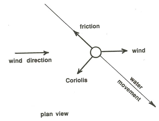
But what about the direction of the current? Think about the balance of forces on a small parcel of fluid at the water surface (Figure \(\PageIndex{1}\)). The surface water feels not only the wind force, in the direction of the wind, but also the Coriolis force, at right angles to the direction of water motion, and a friction force exerted by the slower water below, in the direction opposite to the surface water motion. Because the parcel of surface water is not accelerating, these three forces have to add up to zero. From Figure \(\PageIndex{1}\) you can see that the only way you can balance these three forces is for the surface water to move at some angle between \(0^{\circ}\) and \(90^{\circ}\) to one side of the wind direction—to the right of the wind in the Northern Hemisphere and to the left of the wind in the Southern Hemisphere.

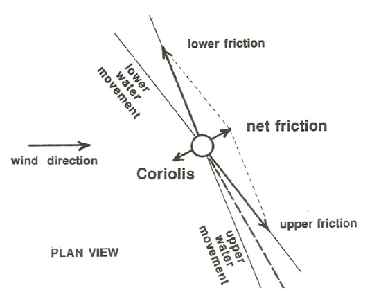
Now look at a slightly lower layer of water. A frictional force is exerted on its upper surface by the overlying layer, and a frictional force is exerted on its lower surface by the underlying layer. The same line of reasoning we used in Chapter 1 for flow between parallel plates moving relative to each other suggests that these two frictional forces are of the same magnitude but in different directions. But there has to be some left-over net friction force, because that is the only force that is available to balance the Coriolis force. For there to be a friction force directed opposite to the Coriolis force, the velocity vector must be turning continuously away from the wind direction with depth! See Figure \(\PageIndex{2}\) for how this works. And so on for each successively deeper layer: each lower layer of water moves in a direction farther to the right (or left) of the surface wind direction.

The only trouble with the argument in the last two paragraphs is that it is discrete rather than continuous. To solve the problem right, we would have to write the differential equations of motion, subject to the appropriate boundary conditions, and solve them for the vertical distribution of current speed and direction, both of which must of course vary continuously with depth. But the above argument gives you the qualitative physical essence of what is happening.
This problem was first solved analytically by Sven Ekman, a Norwegian physical oceanographer, in 1905. The assumptions behind the solution are that the surface wind is uniform in both speed and direction everywhere and that the ocean is of infinite extent horizontally, so that water does not get piled up in the downwind direction to create an extra force in the form of a horizontal pressure gradient and complicate matters, and also that the ocean is infinitely deep. In case you want to play around with the solution, here it is:
\begin{array}{l}{u=U_{\mathrm{o}} e^{-(\pi / D) z} \cos {[(\pi / 4)-(\pi / D) z]}} \\ {v=U_{\mathrm{o}} e^{-(\pi / D) z} \sin {[(\pi / 4)-(\pi / D) z]}} \label {7.8} \end{array}
where \(v\) is the velocity component at any depth in the wind direction, \(u\) is the velocity component to the right of the wind direction, \(z\) is depth below the water surface, \(U_{\text{o}}\) is the water speed at the surface, and \(D\) is a parameter that contains the water density \(\rho\), the Coriolis parameter \(f\), and a viscosity coefficient \(A\):
\[D=\pi \sqrt{\frac{A}{\rho f}} \label{7.9} \]
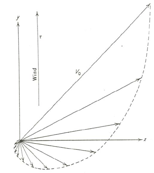
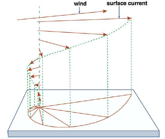
What Equations \ref{7.8} tell you is that at the water surface the velocity is directed at exactly \(45^{\circ}\) to the right of the wind, and with depth the direction of the velocity swings farther and farther to the right while the speed falls off exponentially. Figures \(\PageIndex{3}\)A and \(\PageIndex{3}\)B show two graphical views of the velocity profile with depth. You can see from these figures why the solution is called the Ekman spiral!


Here are some interesting properties of Equations \ref{7.8}. If you substitute \(z = D\) into the equations, you find that at depth \(D\) the velocity components are
\begin{array}{l}{u=U_{0} e^{-\pi} \cos (\pi / 4-\pi)} \\ {v=U_{0} e^{-\pi} \sin (\pi / 4-\pi)} \label{7.10} \end{array}
which tell you that at depth \(D\) the speed has decreased to \(e^{- \pi }\) times the surface velocity (which is less than five percent), and the direction is opposite to the surface current! One can also find the total mass transport of water involved in this Ekman-spiral current, by multiplying the velocity components \(u\) and \(v\) by the water density \(\rho\) and integrating Equations \ref{7.8} over the depth from \(0\) to \(\infty\). The result is spectacular: the net transport of water is directed at exactly \(90^{\circ}\) to the surface wind! I suppose that will seem counterintuitive, but such are the mysteries of the Coriolis effect.


