
11.4: Unit Cells and Lattices in Three Dimensions
- Page ID
- 18397

\( \newcommand{\vecs}[1]{\overset { \scriptstyle \rightharpoonup} {\mathbf{#1}} } \)
\( \newcommand{\vecd}[1]{\overset{-\!-\!\rightharpoonup}{\vphantom{a}\smash {#1}}} \)
\( \newcommand{\id}{\mathrm{id}}\) \( \newcommand{\Span}{\mathrm{span}}\)
( \newcommand{\kernel}{\mathrm{null}\,}\) \( \newcommand{\range}{\mathrm{range}\,}\)
\( \newcommand{\RealPart}{\mathrm{Re}}\) \( \newcommand{\ImaginaryPart}{\mathrm{Im}}\)
\( \newcommand{\Argument}{\mathrm{Arg}}\) \( \newcommand{\norm}[1]{\| #1 \|}\)
\( \newcommand{\inner}[2]{\langle #1, #2 \rangle}\)
\( \newcommand{\Span}{\mathrm{span}}\)
\( \newcommand{\id}{\mathrm{id}}\)
\( \newcommand{\Span}{\mathrm{span}}\)
\( \newcommand{\kernel}{\mathrm{null}\,}\)
\( \newcommand{\range}{\mathrm{range}\,}\)
\( \newcommand{\RealPart}{\mathrm{Re}}\)
\( \newcommand{\ImaginaryPart}{\mathrm{Im}}\)
\( \newcommand{\Argument}{\mathrm{Arg}}\)
\( \newcommand{\norm}[1]{\| #1 \|}\)
\( \newcommand{\inner}[2]{\langle #1, #2 \rangle}\)
\( \newcommand{\Span}{\mathrm{span}}\) \( \newcommand{\AA}{\unicode[.8,0]{x212B}}\)
\( \newcommand{\vectorA}[1]{\vec{#1}} % arrow\)
\( \newcommand{\vectorAt}[1]{\vec{\text{#1}}} % arrow\)
\( \newcommand{\vectorB}[1]{\overset { \scriptstyle \rightharpoonup} {\mathbf{#1}} } \)
\( \newcommand{\vectorC}[1]{\textbf{#1}} \)
\( \newcommand{\vectorD}[1]{\overrightarrow{#1}} \)
\( \newcommand{\vectorDt}[1]{\overrightarrow{\text{#1}}} \)
\( \newcommand{\vectE}[1]{\overset{-\!-\!\rightharpoonup}{\vphantom{a}\smash{\mathbf {#1}}}} \)
\( \newcommand{\vecs}[1]{\overset { \scriptstyle \rightharpoonup} {\mathbf{#1}} } \)
\( \newcommand{\vecd}[1]{\overset{-\!-\!\rightharpoonup}{\vphantom{a}\smash {#1}}} \)
\(\newcommand{\avec}{\mathbf a}\) \(\newcommand{\bvec}{\mathbf b}\) \(\newcommand{\cvec}{\mathbf c}\) \(\newcommand{\dvec}{\mathbf d}\) \(\newcommand{\dtil}{\widetilde{\mathbf d}}\) \(\newcommand{\evec}{\mathbf e}\) \(\newcommand{\fvec}{\mathbf f}\) \(\newcommand{\nvec}{\mathbf n}\) \(\newcommand{\pvec}{\mathbf p}\) \(\newcommand{\qvec}{\mathbf q}\) \(\newcommand{\svec}{\mathbf s}\) \(\newcommand{\tvec}{\mathbf t}\) \(\newcommand{\uvec}{\mathbf u}\) \(\newcommand{\vvec}{\mathbf v}\) \(\newcommand{\wvec}{\mathbf w}\) \(\newcommand{\xvec}{\mathbf x}\) \(\newcommand{\yvec}{\mathbf y}\) \(\newcommand{\zvec}{\mathbf z}\) \(\newcommand{\rvec}{\mathbf r}\) \(\newcommand{\mvec}{\mathbf m}\) \(\newcommand{\zerovec}{\mathbf 0}\) \(\newcommand{\onevec}{\mathbf 1}\) \(\newcommand{\real}{\mathbb R}\) \(\newcommand{\twovec}[2]{\left[\begin{array}{r}#1 \\ #2 \end{array}\right]}\) \(\newcommand{\ctwovec}[2]{\left[\begin{array}{c}#1 \\ #2 \end{array}\right]}\) \(\newcommand{\threevec}[3]{\left[\begin{array}{r}#1 \\ #2 \\ #3 \end{array}\right]}\) \(\newcommand{\cthreevec}[3]{\left[\begin{array}{c}#1 \\ #2 \\ #3 \end{array}\right]}\) \(\newcommand{\fourvec}[4]{\left[\begin{array}{r}#1 \\ #2 \\ #3 \\ #4 \end{array}\right]}\) \(\newcommand{\cfourvec}[4]{\left[\begin{array}{c}#1 \\ #2 \\ #3 \\ #4 \end{array}\right]}\) \(\newcommand{\fivevec}[5]{\left[\begin{array}{r}#1 \\ #2 \\ #3 \\ #4 \\ #5 \\ \end{array}\right]}\) \(\newcommand{\cfivevec}[5]{\left[\begin{array}{c}#1 \\ #2 \\ #3 \\ #4 \\ #5 \\ \end{array}\right]}\) \(\newcommand{\mattwo}[4]{\left[\begin{array}{rr}#1 \amp #2 \\ #3 \amp #4 \\ \end{array}\right]}\) \(\newcommand{\laspan}[1]{\text{Span}\{#1\}}\) \(\newcommand{\bcal}{\cal B}\) \(\newcommand{\ccal}{\cal C}\) \(\newcommand{\scal}{\cal S}\) \(\newcommand{\wcal}{\cal W}\) \(\newcommand{\ecal}{\cal E}\) \(\newcommand{\coords}[2]{\left\{#1\right\}_{#2}}\) \(\newcommand{\gray}[1]{\color{gray}{#1}}\) \(\newcommand{\lgray}[1]{\color{lightgray}{#1}}\) \(\newcommand{\rank}{\operatorname{rank}}\) \(\newcommand{\row}{\text{Row}}\) \(\newcommand{\col}{\text{Col}}\) \(\renewcommand{\row}{\text{Row}}\) \(\newcommand{\nul}{\text{Nul}}\) \(\newcommand{\var}{\text{Var}}\) \(\newcommand{\corr}{\text{corr}}\) \(\newcommand{\len}[1]{\left|#1\right|}\) \(\newcommand{\bbar}{\overline{\bvec}}\) \(\newcommand{\bhat}{\widehat{\bvec}}\) \(\newcommand{\bperp}{\bvec^\perp}\) \(\newcommand{\xhat}{\widehat{\xvec}}\) \(\newcommand{\vhat}{\widehat{\vvec}}\) \(\newcommand{\uhat}{\widehat{\uvec}}\) \(\newcommand{\what}{\widehat{\wvec}}\) \(\newcommand{\Sighat}{\widehat{\Sigma}}\) \(\newcommand{\lt}{<}\) \(\newcommand{\gt}{>}\) \(\newcommand{\amp}{&}\) \(\definecolor{fillinmathshade}{gray}{0.9}\)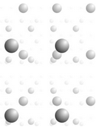
In two dimensions, patterns are made of unit cells and lattices describe how unit cells and motifs repeat. These relationships are the same in three dimensions. Figure 11.32, for example, shows a single atom repeated an indefinite number of times and disappearing into the distance. Choose any four nearest neighbor atoms and you can connect them to get a 3D unit cell that is the basis for the entire atomic array.
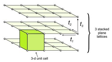
In two dimensions, two vectors describe the translation that relates lattice points. To move from two dimensions (planes) to three dimensions (space), we need only to define a third vector, t3, that translates a plane lattice some distance where it is repeated. We continue this process many times to get a space lattice. Figure 11.33 shows an example.
We can start with any of the two-dimensional plane lattices. The third translation may be orthogonal to one or both of the first two translations, but it need not be. Its magnitude may be the same as one or both of the first two translations, or not. We can envision space lattices as identical points that repeat indefinitely in three-dimensional space.
(Note that, for convenience, in this and subsequent drawings, we are choosing unit cells with lattice points at their corners. But we could choose unit cells with lattice points at their centers or anywhere else in the cell, because lattice points are simply patterns showing how unit cells repeat. It makes no difference if the lattice point corresponds to the corner, center, or any other point in the motif.)
In Figure 11.33, we start with a square lattice, and choose a third translation vector (t3) that is equal in magnitude and also perpendicular to the first two. The result is in an overall cubic lattice. Connecting eight nearest-neighbor lattice points gives us a cubic unit cell. The plane lattices had symmetry 4mm; the cubic unit cell has symmetry 4/m32/m (described in the previous chapter).
If we stack a square net directly above another square net, as in Figure 11.33, the 4-fold rotation axis and the mirror planes line up and we preserve all symmetry. But, suppose the third translation is not perpendicular to the first two, and each square net is slightly offset from the ones above and below it. If so, rotation axes and mirrors in the different nets will not line up. The resulting space lattice may contain no 4-fold axes and no mirrors.
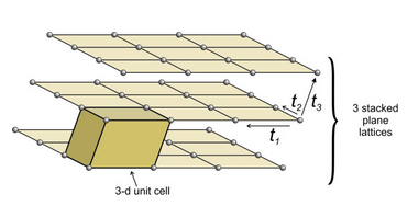
Figure 11.34 shows an example of losing symmetry when nets are stacked with an offset. In this figure, we started with an orthonet. The third translation (t3) is neither perpendicular to, nor of the same magnitude as, either of the other two. Each plane lattice is offset slightly to the right compared with the one below it. The result is a unit cell that has rectangular faces on four sides and parallelograms on two. It is called a monoclinic unit cell (because one angle at each corner is not 90o. An individual orthonet contains mirror planes and 2-fold axes perpendicular to the net. But because, in this example, the third translation was not perpendicular to the first two, those mirrors and rotation axes do not persist in the space lattice, nor in the unit cell. The orthonet has symmetry 2mm; the unit cell has symmetry 2/m. The 2/m axis is perpendicular to the front parallelogram face.
If we consider all possible combinations of plane lattices and a third translation, we come up with seven fundamental unit cell shapes (Figure 11.35). Two of the unit cells, the hexagonal prism and the rhombohedron, are commonly grouped because they both derive from stacking hexanets. If we stack hexanets one above another, we preserve the 6-fold rotation axis and get a hexagonal prism. If the nets are offset, we may instead preserve a 3-fold rotation axis and get a rhombohedron.
You can think of these 3D shapes as the shapes that bricks can have if they fit together without spaces between them. We made a similar analogy to tiles when we were looking at 2D symmetry earlier in this chapter. Just like the tile shapes, more complex brick shapes are possible. But it can be shown that they are all equivalent to one of the seven below.
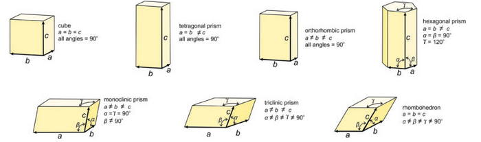
These seven unit cell shapes have unique symmetries: 4/m32/m (cube), 4/m2/m2/m (tetragonal prism), 2/m2/m2/m (orthorhombic prism), 6/m2/m2/m (hexagonal prism), 2/m (monoclinic prism), 1 (triclinic prism), and 32/m (rhombohedron). Each unit cell corresponds to the one of the seven crystal systems introduced in the previous chapter: cubic, tetragonal, orthorhombic, hexagonal, monoclinic, triclinic, and rhombohedral. The symmetry of each unit cell seen here is the same as the symmetry of the general form in each system. A third law of crystallography is that:
blank ■The symmetries of the unit cells are the same as the point groups of greatest symmetry in each of the crystal systems.
All minerals that belong to the cubic system have cubic unit cells with symmetry 4/m32/m. Their crystals, however may have less symmetry. Similarly, all minerals that belong to the tetragonal system have tetragonal unit cells. Tetragonal crystals may have 4/m2/m2/m symmetry but may have less. This same kind of thinking applies to crystals in the other 5 systems, too.
We describe the shapes of unit cells with unit cell parameters that include a, b, and c, the length of unit cell edges, and α, β, and γ, the angles between cell edges. By convention, the angle between the a and b edges is γ (c in the Greek alphabet), the angle between a and c is β (b in the Greek alphabet), and the angle between b and c is α (a in the Greek alphabet). As seen in Figure 11.35, in cubic unit cells, a, b, and c are equal, and all angles are 90o. In tetragonal unit cells, a and b are equal and all angles are 90o. In orthorhombic unit cells, the three cell edges have different lengths, but all angles are 90o. In hexagonal unit cells, a and b have equal lengths, and the angle between a and b (γ) is 120o. In monoclinic unit cells, a, b and c are all different. α and γ are 90o, but β can have any value. (This is the general convention, but sometimes the non-90o angle is chosen as one of the other angles instead of β.) In triclinic unit cells, all cell edges are different lengths and all angles are different and not 90o. And in rhombohedral unit cells, the cell edges are all the same length, and the angles at the corners are the same for all faces, but are not 90o.
The seven distinct unit cell shapes shown above in Figure 11.35 are all that are possible. The seven are primitive – they contain one lattice point in total. But stacking plane lattices can lead to other, nonprimitive, unit cells that have one of the seven shapes we have seen. Figure 11.36 shows three examples.
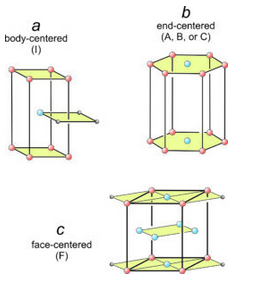
In Figure 11.36a, square nets have been stacked so that every other net is offset. One square from each of three layers is shown. The offset layer puts an extra lattice point (blue) in the center of a tetragonal prism. This is an example of a body-centered unit cell, symbolized by the letter I.
In Figure 11.36b, we put a hexanet directly above another. The result is a hexagonal prism with extra lattice points (blue) in the centers of its top and bottom. This is an example of an end-centered unit cell, symbolized by the letters A, B, or C, depending on which pair of faces contain the extra lattice points.
In Figure 11.36c, diamond nets are stacked with the middle layer offset. This produced an orthorhombic prism that contains extra lattice points at the centers of every face. This is an example of a face-centered unit cell, symbolized by the letter F.