
10.3: From Points to Crystal Faces and Forms
- Page ID
- 18474

\( \newcommand{\vecs}[1]{\overset { \scriptstyle \rightharpoonup} {\mathbf{#1}} } \)
\( \newcommand{\vecd}[1]{\overset{-\!-\!\rightharpoonup}{\vphantom{a}\smash {#1}}} \)
\( \newcommand{\id}{\mathrm{id}}\) \( \newcommand{\Span}{\mathrm{span}}\)
( \newcommand{\kernel}{\mathrm{null}\,}\) \( \newcommand{\range}{\mathrm{range}\,}\)
\( \newcommand{\RealPart}{\mathrm{Re}}\) \( \newcommand{\ImaginaryPart}{\mathrm{Im}}\)
\( \newcommand{\Argument}{\mathrm{Arg}}\) \( \newcommand{\norm}[1]{\| #1 \|}\)
\( \newcommand{\inner}[2]{\langle #1, #2 \rangle}\)
\( \newcommand{\Span}{\mathrm{span}}\)
\( \newcommand{\id}{\mathrm{id}}\)
\( \newcommand{\Span}{\mathrm{span}}\)
\( \newcommand{\kernel}{\mathrm{null}\,}\)
\( \newcommand{\range}{\mathrm{range}\,}\)
\( \newcommand{\RealPart}{\mathrm{Re}}\)
\( \newcommand{\ImaginaryPart}{\mathrm{Im}}\)
\( \newcommand{\Argument}{\mathrm{Arg}}\)
\( \newcommand{\norm}[1]{\| #1 \|}\)
\( \newcommand{\inner}[2]{\langle #1, #2 \rangle}\)
\( \newcommand{\Span}{\mathrm{span}}\) \( \newcommand{\AA}{\unicode[.8,0]{x212B}}\)
\( \newcommand{\vectorA}[1]{\vec{#1}} % arrow\)
\( \newcommand{\vectorAt}[1]{\vec{\text{#1}}} % arrow\)
\( \newcommand{\vectorB}[1]{\overset { \scriptstyle \rightharpoonup} {\mathbf{#1}} } \)
\( \newcommand{\vectorC}[1]{\textbf{#1}} \)
\( \newcommand{\vectorD}[1]{\overrightarrow{#1}} \)
\( \newcommand{\vectorDt}[1]{\overrightarrow{\text{#1}}} \)
\( \newcommand{\vectE}[1]{\overset{-\!-\!\rightharpoonup}{\vphantom{a}\smash{\mathbf {#1}}}} \)
\( \newcommand{\vecs}[1]{\overset { \scriptstyle \rightharpoonup} {\mathbf{#1}} } \)
\( \newcommand{\vecd}[1]{\overset{-\!-\!\rightharpoonup}{\vphantom{a}\smash {#1}}} \)
\(\newcommand{\avec}{\mathbf a}\) \(\newcommand{\bvec}{\mathbf b}\) \(\newcommand{\cvec}{\mathbf c}\) \(\newcommand{\dvec}{\mathbf d}\) \(\newcommand{\dtil}{\widetilde{\mathbf d}}\) \(\newcommand{\evec}{\mathbf e}\) \(\newcommand{\fvec}{\mathbf f}\) \(\newcommand{\nvec}{\mathbf n}\) \(\newcommand{\pvec}{\mathbf p}\) \(\newcommand{\qvec}{\mathbf q}\) \(\newcommand{\svec}{\mathbf s}\) \(\newcommand{\tvec}{\mathbf t}\) \(\newcommand{\uvec}{\mathbf u}\) \(\newcommand{\vvec}{\mathbf v}\) \(\newcommand{\wvec}{\mathbf w}\) \(\newcommand{\xvec}{\mathbf x}\) \(\newcommand{\yvec}{\mathbf y}\) \(\newcommand{\zvec}{\mathbf z}\) \(\newcommand{\rvec}{\mathbf r}\) \(\newcommand{\mvec}{\mathbf m}\) \(\newcommand{\zerovec}{\mathbf 0}\) \(\newcommand{\onevec}{\mathbf 1}\) \(\newcommand{\real}{\mathbb R}\) \(\newcommand{\twovec}[2]{\left[\begin{array}{r}#1 \\ #2 \end{array}\right]}\) \(\newcommand{\ctwovec}[2]{\left[\begin{array}{c}#1 \\ #2 \end{array}\right]}\) \(\newcommand{\threevec}[3]{\left[\begin{array}{r}#1 \\ #2 \\ #3 \end{array}\right]}\) \(\newcommand{\cthreevec}[3]{\left[\begin{array}{c}#1 \\ #2 \\ #3 \end{array}\right]}\) \(\newcommand{\fourvec}[4]{\left[\begin{array}{r}#1 \\ #2 \\ #3 \\ #4 \end{array}\right]}\) \(\newcommand{\cfourvec}[4]{\left[\begin{array}{c}#1 \\ #2 \\ #3 \\ #4 \end{array}\right]}\) \(\newcommand{\fivevec}[5]{\left[\begin{array}{r}#1 \\ #2 \\ #3 \\ #4 \\ #5 \\ \end{array}\right]}\) \(\newcommand{\cfivevec}[5]{\left[\begin{array}{c}#1 \\ #2 \\ #3 \\ #4 \\ #5 \\ \end{array}\right]}\) \(\newcommand{\mattwo}[4]{\left[\begin{array}{rr}#1 \amp #2 \\ #3 \amp #4 \\ \end{array}\right]}\) \(\newcommand{\laspan}[1]{\text{Span}\{#1\}}\) \(\newcommand{\bcal}{\cal B}\) \(\newcommand{\ccal}{\cal C}\) \(\newcommand{\scal}{\cal S}\) \(\newcommand{\wcal}{\cal W}\) \(\newcommand{\ecal}{\cal E}\) \(\newcommand{\coords}[2]{\left\{#1\right\}_{#2}}\) \(\newcommand{\gray}[1]{\color{gray}{#1}}\) \(\newcommand{\lgray}[1]{\color{lightgray}{#1}}\) \(\newcommand{\rank}{\operatorname{rank}}\) \(\newcommand{\row}{\text{Row}}\) \(\newcommand{\col}{\text{Col}}\) \(\renewcommand{\row}{\text{Row}}\) \(\newcommand{\nul}{\text{Nul}}\) \(\newcommand{\var}{\text{Var}}\) \(\newcommand{\corr}{\text{corr}}\) \(\newcommand{\len}[1]{\left|#1\right|}\) \(\newcommand{\bbar}{\overline{\bvec}}\) \(\newcommand{\bhat}{\widehat{\bvec}}\) \(\newcommand{\bperp}{\bvec^\perp}\) \(\newcommand{\xhat}{\widehat{\xvec}}\) \(\newcommand{\vhat}{\widehat{\vvec}}\) \(\newcommand{\uhat}{\widehat{\uvec}}\) \(\newcommand{\what}{\widehat{\wvec}}\) \(\newcommand{\Sighat}{\widehat{\Sigma}}\) \(\newcommand{\lt}{<}\) \(\newcommand{\gt}{>}\) \(\newcommand{\amp}{&}\) \(\definecolor{fillinmathshade}{gray}{0.9}\)In the preceding discussion, we talked about generic points and symmetry on stereo diagrams. And, we looked at some crystals with different symmetries. Now we will return to crystals and make the connection between crystal faces and stereo diagrams.
Crystallographers use the term form to describe a set of identically-shaped crystal faces related by symmetry. Use of this term is unfortunate, because most of us think of form as meaning shape. Further confusion arises because a single crystal may contain multiple forms, and a single form may have as many as 48 faces. Additionally, two crystals with identical forms may appear different if the forms are of different sizes. Nonetheless, the term form is firmly established in crystallography and unlikely to disappear. Crystallographers use various approaches to name forms, but A. F. Rogers’s system, published in 1935, is commonly used in the United States (Box 10-3).
Consider a crystal shaped like a shoe box (Figure 10.29). It contains three pairs of identical faces (opposite sides of the crystal). So, the crystal contains three forms. Figure 10.29 shows how orientations of the horizontal and vertical crystal faces may be shown on a stereo diagram. We depict the horizontal faces on the top and bottom of a crystal as solid and open dots, respectively, in the middle of the circle (drawings a and b).
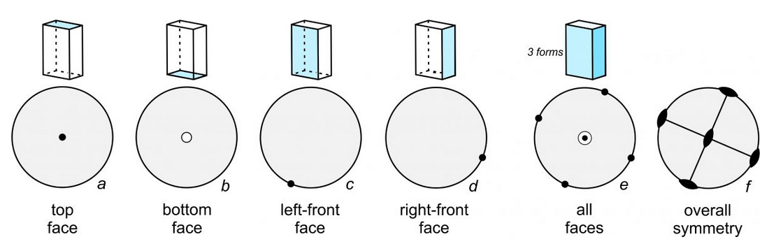
Vertical faces always plot as dots on the outside of the circle (drawings c and d) and are situated to show the aspect of the face (the direction the face is pointing). This crystal contains four vertical faces at 90o to each other, and the crystal is oriented at an arbitrary angle. Drawing e shows all six of the faces on one diagram. The bull’s-eye at the center represents the top and bottom faces, and the dots on the circle represent the four vertical faces. Drawing f shows the overall symmetry. This crystal contains three perpendicular mirror planes and three perpendicular 2-fold axes.
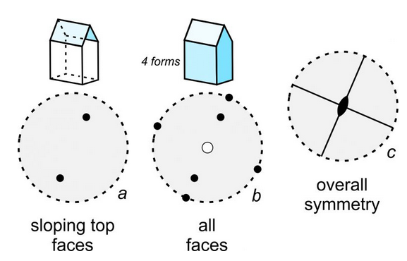
Many crystals contain sloping faces. If so, they plot as dots (or circles) that are somewhere between the center and the outside of a stereo diagram. And, we orient them to show their aspect. The house-shaped crystal seen in Figure 10.30 contains four forms – the same three that are in the shoe box we just saw plus a form composed of the two identical sloping faces on top. Black dots in drawing a show the sloping top faces. All faces are depicted in drawing b. Note that the bottom face is the only one that is an open circle. It is the only face below the plane of the page. The overall symmetry of this crystal (drawing c) is less than the symmetry of the shoe box described above. This crystal contains only two mirrors and a single 2-fold axis.
Earlier in this chapter, we introduced the idea of zones in crystals. In Figure 10.30b, five of the dots/circles representing faces are on a line (that is nearly vertical in the drawing). This means the faces are all parallel to a single horizontal direction; it means that together they form a zone.
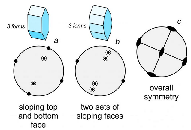
A crystal face that is almost, but not quite, horizontal will plot as a point near the center of a stereo diagram. A face that is almost vertical will plot close to the circle on the outside. And, faces with slopes of around 45o will plot halfway between the center and the outside. So, the distance a point is from the centers describes the slope of the face. Figure 10.31 shows an example. Crystal a, containing three forms, has sloping faces on both the top and bottom of the crystal. Because the top faces are above the bottom faces, they appear as (two) bull’s-eyes within the circle. Crystal b (also three forms) contains two sets of sloping faces on the top and bottom, so the drawing contains four bull’s-eyes. The symbols closest to the outside of the circle represent the four faces that are almost vertical. The bull’s-eyes representing all the sloping faces indicate a zone; all faces in the zone are parallel to a single horizontal line. Drawing c shows the overall symmetry of both crystals; they contain three 2-fold axes and three mirrors. Although the two crystals in Figure 10.31 have a different number of faces, their symmetries are the same.
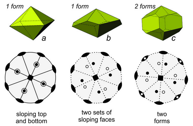
Figure 10.32 shows three more examples of crystals and stereo diagrams for each. Crystal a has a lot of symmetry – a 4-fold axis, four 2-fold axes and five mirror planes (four vertical and one horizontal). Crystal b also has a 4-fold axis and four 2-fold axes but contains no mirrors. Crystal c has the same symmetry as crystal b but contains four additional vertical prism faces. Unlike the previous figures, the stereo diagrams in Figure 10.32 show symmetry elements and face orientations (dots/circles) in the same diagram. This is standard practice but sometimes leads to a cluttered and confusing drawing, especially if points representing faces fall on top of symmetry elements.
When creating stereo diagrams, we orient a crystal so that rotation axes are vertical or horizontal (in the plane of the page or perpendicular to the page) if we can. This is what we did in Figure 10.32 and previous figures. Because mirror planes are generally parallel or perpendicular to rotation axes, mirrors too are horizontal or vertical most of the time.
If only looking at a stereo diagram, and not a crystal, we can rotate the diagram so that symmetry elements are mostly vertical or horizontal on the page. That means, for example, that if there is only one mirror plane present, we usually align it vertically and it appears as a vertical line in the diagram. But, if we wish to see side faces on a crystal, we usually rotate the crystal some arbitrary angle or the faces will not be visible. Suppose for example we view a cube perpendicular to one of its faces. We will only see a single square face – which is not very revealing. When we look at a cube from an oblique angle, we can see three faces and get a much better idea of its overall shape.
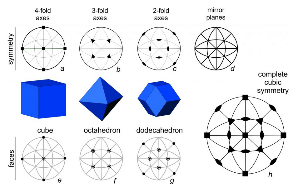
Earlier in this chapter, we observed that a cube and an octahedron have the same symmetry. It is worthwhile to revisit that idea using stereo diagrams. Consider the drawings of a cube, octahedron, and dodecahedron above in Figure 10.33. They have identical symmetry that includes 4-fold, 3-fold, and 2-fold rotation axes and many mirrors. We call this symmetry cubic symmetry. The large stereo diagram in drawing h shows all the elements of cubic symmetry.
In Figure 10.33, stereo diagram a above the cube shows the orientation of the 4-fold axes; they are perpendicular to the cube faces. Diagram b above the octahedron shows the orientation of the 3-fold axes; they are perpendicular to the octahedron faces. And, diagram c above the dodecahedron shows the orientation of the 2-fold axes are; they are perpendicular to the dodecahedron faces. Diagram d shows the orientations of the mirror planes; there is one perpendicular to each of the 4-fold and 2-fold rotation axes. The solid outer circle shows the horizontal mirror that goes through the center of each crystal. The four straight lines that intersect at the center of the diagram show vertical mirrors that bisect the crystal faces or that coincide with face edges. The four arc-shaped curves, halfway between the vertical and horizontal straight lines and the outer circle, show inclined mirrors.