
59.4: Deformation - Faults
- Page ID
- 22857

\( \newcommand{\vecs}[1]{\overset { \scriptstyle \rightharpoonup} {\mathbf{#1}} } \)
\( \newcommand{\vecd}[1]{\overset{-\!-\!\rightharpoonup}{\vphantom{a}\smash {#1}}} \)
\( \newcommand{\dsum}{\displaystyle\sum\limits} \)
\( \newcommand{\dint}{\displaystyle\int\limits} \)
\( \newcommand{\dlim}{\displaystyle\lim\limits} \)
\( \newcommand{\id}{\mathrm{id}}\) \( \newcommand{\Span}{\mathrm{span}}\)
( \newcommand{\kernel}{\mathrm{null}\,}\) \( \newcommand{\range}{\mathrm{range}\,}\)
\( \newcommand{\RealPart}{\mathrm{Re}}\) \( \newcommand{\ImaginaryPart}{\mathrm{Im}}\)
\( \newcommand{\Argument}{\mathrm{Arg}}\) \( \newcommand{\norm}[1]{\| #1 \|}\)
\( \newcommand{\inner}[2]{\langle #1, #2 \rangle}\)
\( \newcommand{\Span}{\mathrm{span}}\)
\( \newcommand{\id}{\mathrm{id}}\)
\( \newcommand{\Span}{\mathrm{span}}\)
\( \newcommand{\kernel}{\mathrm{null}\,}\)
\( \newcommand{\range}{\mathrm{range}\,}\)
\( \newcommand{\RealPart}{\mathrm{Re}}\)
\( \newcommand{\ImaginaryPart}{\mathrm{Im}}\)
\( \newcommand{\Argument}{\mathrm{Arg}}\)
\( \newcommand{\norm}[1]{\| #1 \|}\)
\( \newcommand{\inner}[2]{\langle #1, #2 \rangle}\)
\( \newcommand{\Span}{\mathrm{span}}\) \( \newcommand{\AA}{\unicode[.8,0]{x212B}}\)
\( \newcommand{\vectorA}[1]{\vec{#1}} % arrow\)
\( \newcommand{\vectorAt}[1]{\vec{\text{#1}}} % arrow\)
\( \newcommand{\vectorB}[1]{\overset { \scriptstyle \rightharpoonup} {\mathbf{#1}} } \)
\( \newcommand{\vectorC}[1]{\textbf{#1}} \)
\( \newcommand{\vectorD}[1]{\overrightarrow{#1}} \)
\( \newcommand{\vectorDt}[1]{\overrightarrow{\text{#1}}} \)
\( \newcommand{\vectE}[1]{\overset{-\!-\!\rightharpoonup}{\vphantom{a}\smash{\mathbf {#1}}}} \)
\( \newcommand{\vecs}[1]{\overset { \scriptstyle \rightharpoonup} {\mathbf{#1}} } \)
\(\newcommand{\longvect}{\overrightarrow}\)
\( \newcommand{\vecd}[1]{\overset{-\!-\!\rightharpoonup}{\vphantom{a}\smash {#1}}} \)
\(\newcommand{\avec}{\mathbf a}\) \(\newcommand{\bvec}{\mathbf b}\) \(\newcommand{\cvec}{\mathbf c}\) \(\newcommand{\dvec}{\mathbf d}\) \(\newcommand{\dtil}{\widetilde{\mathbf d}}\) \(\newcommand{\evec}{\mathbf e}\) \(\newcommand{\fvec}{\mathbf f}\) \(\newcommand{\nvec}{\mathbf n}\) \(\newcommand{\pvec}{\mathbf p}\) \(\newcommand{\qvec}{\mathbf q}\) \(\newcommand{\svec}{\mathbf s}\) \(\newcommand{\tvec}{\mathbf t}\) \(\newcommand{\uvec}{\mathbf u}\) \(\newcommand{\vvec}{\mathbf v}\) \(\newcommand{\wvec}{\mathbf w}\) \(\newcommand{\xvec}{\mathbf x}\) \(\newcommand{\yvec}{\mathbf y}\) \(\newcommand{\zvec}{\mathbf z}\) \(\newcommand{\rvec}{\mathbf r}\) \(\newcommand{\mvec}{\mathbf m}\) \(\newcommand{\zerovec}{\mathbf 0}\) \(\newcommand{\onevec}{\mathbf 1}\) \(\newcommand{\real}{\mathbb R}\) \(\newcommand{\twovec}[2]{\left[\begin{array}{r}#1 \\ #2 \end{array}\right]}\) \(\newcommand{\ctwovec}[2]{\left[\begin{array}{c}#1 \\ #2 \end{array}\right]}\) \(\newcommand{\threevec}[3]{\left[\begin{array}{r}#1 \\ #2 \\ #3 \end{array}\right]}\) \(\newcommand{\cthreevec}[3]{\left[\begin{array}{c}#1 \\ #2 \\ #3 \end{array}\right]}\) \(\newcommand{\fourvec}[4]{\left[\begin{array}{r}#1 \\ #2 \\ #3 \\ #4 \end{array}\right]}\) \(\newcommand{\cfourvec}[4]{\left[\begin{array}{c}#1 \\ #2 \\ #3 \\ #4 \end{array}\right]}\) \(\newcommand{\fivevec}[5]{\left[\begin{array}{r}#1 \\ #2 \\ #3 \\ #4 \\ #5 \\ \end{array}\right]}\) \(\newcommand{\cfivevec}[5]{\left[\begin{array}{c}#1 \\ #2 \\ #3 \\ #4 \\ #5 \\ \end{array}\right]}\) \(\newcommand{\mattwo}[4]{\left[\begin{array}{rr}#1 \amp #2 \\ #3 \amp #4 \\ \end{array}\right]}\) \(\newcommand{\laspan}[1]{\text{Span}\{#1\}}\) \(\newcommand{\bcal}{\cal B}\) \(\newcommand{\ccal}{\cal C}\) \(\newcommand{\scal}{\cal S}\) \(\newcommand{\wcal}{\cal W}\) \(\newcommand{\ecal}{\cal E}\) \(\newcommand{\coords}[2]{\left\{#1\right\}_{#2}}\) \(\newcommand{\gray}[1]{\color{gray}{#1}}\) \(\newcommand{\lgray}[1]{\color{lightgray}{#1}}\) \(\newcommand{\rank}{\operatorname{rank}}\) \(\newcommand{\row}{\text{Row}}\) \(\newcommand{\col}{\text{Col}}\) \(\renewcommand{\row}{\text{Row}}\) \(\newcommand{\nul}{\text{Nul}}\) \(\newcommand{\var}{\text{Var}}\) \(\newcommand{\corr}{\text{corr}}\) \(\newcommand{\len}[1]{\left|#1\right|}\) \(\newcommand{\bbar}{\overline{\bvec}}\) \(\newcommand{\bhat}{\widehat{\bvec}}\) \(\newcommand{\bperp}{\bvec^\perp}\) \(\newcommand{\xhat}{\widehat{\xvec}}\) \(\newcommand{\vhat}{\widehat{\vvec}}\) \(\newcommand{\uhat}{\widehat{\uvec}}\) \(\newcommand{\what}{\widehat{\wvec}}\) \(\newcommand{\Sighat}{\widehat{\Sigma}}\) \(\newcommand{\lt}{<}\) \(\newcommand{\gt}{>}\) \(\newcommand{\amp}{&}\) \(\definecolor{fillinmathshade}{gray}{0.9}\)All rock types will ultimately reach a point of failure where they will break permanently and form a fault. Faults are classified based on the type of stress that produced them as well as the movement associated with the two separate blocks of rock. Deformational folding, as discussed above, is largely caused by compressional stress of tectonic collision. Faulting is also the result of tectonic movement however, different fault types are associated with the different types of plate boundaries. The three types of stress, compressional, tensional, and shear, are associated with movement along the three different types of plate boundaries, convergent, divergent and transform.
Reverse and Thrust Faults
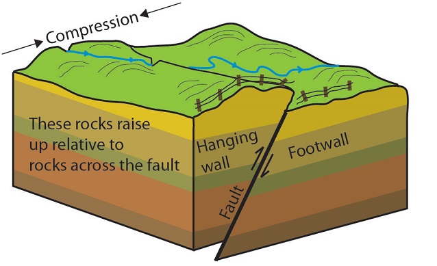
Geologists use block diagrams in an attempt to demonstrate three dimensional movement. The terms hanging wall and footwall refer to the relative position of the blocks after movement. Economic minerals, such as gold, often form along faults planes, and these terms come from where a miner would stand, and where they would hang their lantern as they were mining the minerals along the fault plane.
The block diagram displays horizontal sedimentary strata (layers, or beds, of sedimentary rock). When geologists look at these structures as they occur at a rock exposure, they trace marker beds to determine which block has moved and in what direction. Study the block diagram below of a reverse/thrust fault. Trace the rock layers from one side of the fault to the other.
A reverse fault is caused by compressional stress at convergent plate boundaries.
In a reverse or thrust fault, the hanging wall has moved up relative to the footwall.
The difference between a reverse and thrust fault is the angle of the fault plane. A reverse has a high angle fault plane (the surface separating the two blocks) while a thrust fault has a low angle fault plane. Take a look at the 3D models below to investigate. Once the models load, you can grab them to rotate in 3D. One common misconception by students in identifying faults is that the arrangement of the blocks is static as in the diagram above. This may lead a student to believe that the hanging wall is always on one side in a given type fault (such as on the left in the diagram above). Being able to look at these blocks in 3D allows the student to see that the hanging wall and footwall can be oriented in any direction as they occur in the Earth’s crust.
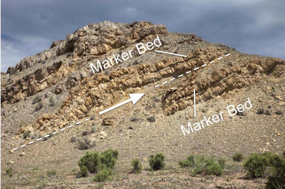
Examples of a Reverse and Thrust Fault, below, to compare with the 3D images above.
Reverse Fault

Thrust Fault
Normal Faults
A normal fault is caused by extensional (tensional) stress at divergent plate boundaries as two plates are moving in opposite directions, away from each other.
In a normal fault, the hanging wall has moved down relative to the footwall.
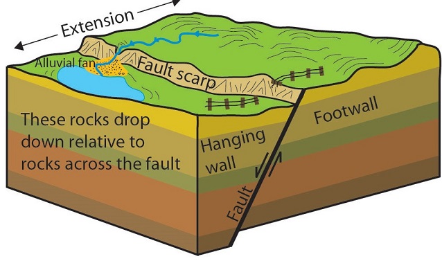
Explore this 3D block structure of a normal fault. Once the models load, you can grab them to rotate in 3D. One common misconception by students in identifying faults is that the arrangement of the blocks is static as in the diagram above. This may lead a student to believe that the hanging wall is always on one side in a given fault (such as on the left in the diagram above). Being able to look at these blocks in 3D allows the student to see that the hanging wall and footwall can be oriented in any direction as they occur in Earth’s crust.


Strike-Slip Faults
Shear stress at a transform plate boundary will produce a strike-slip fault. The fault is named strike-slip because the fracture is along the Earth’s surface and the movement between the blocks is not up or down but “along strike” – a line with a specific direction along Earth’s surface – the line of strike – which is also known as the “fault trace.” The fault plane is typically vertical into the crust and the “slip,” or movement, occurs along the plane. The strike slip fault in the diagram is labeled a “right-lateral” strike-slip fault. If you are standing on one side of the fault trace and looking across to the other side, the movement would appear to be laterally to the right. Note how the stream jogs to the right along the fault trace. In a left-lateral strike-slip fault, the blocks would be moving in the opposite direction.

Let’s take a look at another one of these fantastic before/after Google Earth image GIFs from the Ridgecrest, CA earthquake. This GIF was created by using satellite imagery; in these photos, you are looking down on the land surface as if you are flying overhead in a plane. As you analyze the movement, put yourself on one side of the fault and look across to the the other side. Is this a right-lateral or left-lateral strike-slip fault? Find out below.
Did I Get It? - Quiz
Is the Google Earth image GIF in the text a left-lateral or right lateral strike-slip fault?
a. Left-lateral strike-slip fault
b. Right-lateral strike-slip fault
c. It's nobody's fault!!! :-)
- Answer
-
b. Right-lateral strike-slip fault
The photo in the aerial photo below is of a left-lateral strike-slip fault. Note: if you were standing where the word fault is written and looking across the fault trace to the other side, the motion along fault plane would be to the left.
