7.7: Geologic Structures
- Page ID
- 2552
\( \newcommand{\vecs}[1]{\overset { \scriptstyle \rightharpoonup} {\mathbf{#1}} } \)
\( \newcommand{\vecd}[1]{\overset{-\!-\!\rightharpoonup}{\vphantom{a}\smash {#1}}} \)
\( \newcommand{\dsum}{\displaystyle\sum\limits} \)
\( \newcommand{\dint}{\displaystyle\int\limits} \)
\( \newcommand{\dlim}{\displaystyle\lim\limits} \)
\( \newcommand{\id}{\mathrm{id}}\) \( \newcommand{\Span}{\mathrm{span}}\)
( \newcommand{\kernel}{\mathrm{null}\,}\) \( \newcommand{\range}{\mathrm{range}\,}\)
\( \newcommand{\RealPart}{\mathrm{Re}}\) \( \newcommand{\ImaginaryPart}{\mathrm{Im}}\)
\( \newcommand{\Argument}{\mathrm{Arg}}\) \( \newcommand{\norm}[1]{\| #1 \|}\)
\( \newcommand{\inner}[2]{\langle #1, #2 \rangle}\)
\( \newcommand{\Span}{\mathrm{span}}\)
\( \newcommand{\id}{\mathrm{id}}\)
\( \newcommand{\Span}{\mathrm{span}}\)
\( \newcommand{\kernel}{\mathrm{null}\,}\)
\( \newcommand{\range}{\mathrm{range}\,}\)
\( \newcommand{\RealPart}{\mathrm{Re}}\)
\( \newcommand{\ImaginaryPart}{\mathrm{Im}}\)
\( \newcommand{\Argument}{\mathrm{Arg}}\)
\( \newcommand{\norm}[1]{\| #1 \|}\)
\( \newcommand{\inner}[2]{\langle #1, #2 \rangle}\)
\( \newcommand{\Span}{\mathrm{span}}\) \( \newcommand{\AA}{\unicode[.8,0]{x212B}}\)
\( \newcommand{\vectorA}[1]{\vec{#1}} % arrow\)
\( \newcommand{\vectorAt}[1]{\vec{\text{#1}}} % arrow\)
\( \newcommand{\vectorB}[1]{\overset { \scriptstyle \rightharpoonup} {\mathbf{#1}} } \)
\( \newcommand{\vectorC}[1]{\textbf{#1}} \)
\( \newcommand{\vectorD}[1]{\overrightarrow{#1}} \)
\( \newcommand{\vectorDt}[1]{\overrightarrow{\text{#1}}} \)
\( \newcommand{\vectE}[1]{\overset{-\!-\!\rightharpoonup}{\vphantom{a}\smash{\mathbf {#1}}}} \)
\( \newcommand{\vecs}[1]{\overset { \scriptstyle \rightharpoonup} {\mathbf{#1}} } \)
\(\newcommand{\longvect}{\overrightarrow}\)
\( \newcommand{\vecd}[1]{\overset{-\!-\!\rightharpoonup}{\vphantom{a}\smash {#1}}} \)
\(\newcommand{\avec}{\mathbf a}\) \(\newcommand{\bvec}{\mathbf b}\) \(\newcommand{\cvec}{\mathbf c}\) \(\newcommand{\dvec}{\mathbf d}\) \(\newcommand{\dtil}{\widetilde{\mathbf d}}\) \(\newcommand{\evec}{\mathbf e}\) \(\newcommand{\fvec}{\mathbf f}\) \(\newcommand{\nvec}{\mathbf n}\) \(\newcommand{\pvec}{\mathbf p}\) \(\newcommand{\qvec}{\mathbf q}\) \(\newcommand{\svec}{\mathbf s}\) \(\newcommand{\tvec}{\mathbf t}\) \(\newcommand{\uvec}{\mathbf u}\) \(\newcommand{\vvec}{\mathbf v}\) \(\newcommand{\wvec}{\mathbf w}\) \(\newcommand{\xvec}{\mathbf x}\) \(\newcommand{\yvec}{\mathbf y}\) \(\newcommand{\zvec}{\mathbf z}\) \(\newcommand{\rvec}{\mathbf r}\) \(\newcommand{\mvec}{\mathbf m}\) \(\newcommand{\zerovec}{\mathbf 0}\) \(\newcommand{\onevec}{\mathbf 1}\) \(\newcommand{\real}{\mathbb R}\) \(\newcommand{\twovec}[2]{\left[\begin{array}{r}#1 \\ #2 \end{array}\right]}\) \(\newcommand{\ctwovec}[2]{\left[\begin{array}{c}#1 \\ #2 \end{array}\right]}\) \(\newcommand{\threevec}[3]{\left[\begin{array}{r}#1 \\ #2 \\ #3 \end{array}\right]}\) \(\newcommand{\cthreevec}[3]{\left[\begin{array}{c}#1 \\ #2 \\ #3 \end{array}\right]}\) \(\newcommand{\fourvec}[4]{\left[\begin{array}{r}#1 \\ #2 \\ #3 \\ #4 \end{array}\right]}\) \(\newcommand{\cfourvec}[4]{\left[\begin{array}{c}#1 \\ #2 \\ #3 \\ #4 \end{array}\right]}\) \(\newcommand{\fivevec}[5]{\left[\begin{array}{r}#1 \\ #2 \\ #3 \\ #4 \\ #5 \\ \end{array}\right]}\) \(\newcommand{\cfivevec}[5]{\left[\begin{array}{c}#1 \\ #2 \\ #3 \\ #4 \\ #5 \\ \end{array}\right]}\) \(\newcommand{\mattwo}[4]{\left[\begin{array}{rr}#1 \amp #2 \\ #3 \amp #4 \\ \end{array}\right]}\) \(\newcommand{\laspan}[1]{\text{Span}\{#1\}}\) \(\newcommand{\bcal}{\cal B}\) \(\newcommand{\ccal}{\cal C}\) \(\newcommand{\scal}{\cal S}\) \(\newcommand{\wcal}{\cal W}\) \(\newcommand{\ecal}{\cal E}\) \(\newcommand{\coords}[2]{\left\{#1\right\}_{#2}}\) \(\newcommand{\gray}[1]{\color{gray}{#1}}\) \(\newcommand{\lgray}[1]{\color{lightgray}{#1}}\) \(\newcommand{\rank}{\operatorname{rank}}\) \(\newcommand{\row}{\text{Row}}\) \(\newcommand{\col}{\text{Col}}\) \(\renewcommand{\row}{\text{Row}}\) \(\newcommand{\nul}{\text{Nul}}\) \(\newcommand{\var}{\text{Var}}\) \(\newcommand{\corr}{\text{corr}}\) \(\newcommand{\len}[1]{\left|#1\right|}\) \(\newcommand{\bbar}{\overline{\bvec}}\) \(\newcommand{\bhat}{\widehat{\bvec}}\) \(\newcommand{\bperp}{\bvec^\perp}\) \(\newcommand{\xhat}{\widehat{\xvec}}\) \(\newcommand{\vhat}{\widehat{\vvec}}\) \(\newcommand{\uhat}{\widehat{\uvec}}\) \(\newcommand{\what}{\widehat{\wvec}}\) \(\newcommand{\Sighat}{\widehat{\Sigma}}\) \(\newcommand{\lt}{<}\) \(\newcommand{\gt}{>}\) \(\newcommand{\amp}{&}\) \(\definecolor{fillinmathshade}{gray}{0.9}\)INTRODUCTION
Geologic structures such as faults and folds are the architecture of the earth’s crust. Geologic structures influence the shape of the landscape, determine the degree of landslide hazard, bring old rocks to the surface, bury young rocks, trap petroleum and natural gas, shift during earthquakes, and channel fluids that create economic deposits of metals such as gold and silver.
Folds, faults, and other geologic structures accommodate large forces such as the stress of tectonic plates jostling against each other, and smaller forces such as the stress of gravity pulling on a steep mountainside. An understanding of the structures that shape the earth’s crust can help you see when and where the crust was subjected to pushing or pulling, terrane accretion or crustal rifting.
PHYSICAL BEHAVIOR OF ROCKS: STRESS AND GEOLOGIC STRUCTURES
Before exploring geologic structures, we need to look at how rocks respond to the forces that create the structures. Stress refers to the physical forces that cause rocks to deform. There are three basic types of stress that deform rocks:
- compression (pushing together)
- tension (pulling apart)
- shear (twisting or rotating)
In response to stress, rocks will undergo some form of bending or breaking, or both. The bending or breaking of rock is called deformation or strain.
If rocks tend to break, they are said to be brittle. If a rock breaks, it is said to undergo brittle behavior. If rocks tend to bend without breaking, they are said to be ductile. If a rock bends but is able to return to its original position when the stress is released, it is said to undergo elastic behavior. If a rock bends and stays bent after stress is released, it is said to undergo plastic behavior.
A combination of elastic and brittle behavior causes earthquakes. Rocks get bent in an elastic fashion until they reach their limit, then they break in brittle fashion. The rocks on either side of a break act like rubber bands and snap back into their original shape. The snap is an earthquake. The break along which the rocks slide back to their original shape is a fault.
Earthquakes and faults occur in the shallow crust, where rocks are relatively cold and therefore brittle. In the deep crust and in the earth’s mantle, rocks are very hot and subject to high pressure caused by the weight of the overlying rock. The heat and pressure cause deep crustal and mantle rocks to be ductile. In fact, rocks deep in the continental crust and upper mantle can be so hot and soft that they behave almost like a slow-moving liquid, even though they are actually solid. They “flow,” or bend in a plastic manner, at a geological pace.
Now let us look at the specific types of geologic structures, the breaks and bends that deform rock in response to stress.
FOLDS
Ductile rocks behave plastically and become folded in response to stress. Even in the shallow crust where rocks are cool and relatively brittle, folding can occur if the stress is slow and steady and gives the rock enough time to gradually bend. If the stress is applied too quickly, rocks in the shallow crust will behave as brittle solids and break. Deeper in the crust, where the rocks are more ductile, folding happens more readily, even when the stress and strain occurs rapidly.
Anticlines and Synclines
The most basic types of folds are anticlines and synclines. Imagine a rug, the sides of which have been pushed toward each other forming ridges and valleys – the ridges are “up” folds and the valleys are “down” folds. In terms of geologic structures, the up folds are called anticlines and the down folds are called synclines.
In block diagrams like those shown below, the top of the block is the horizontal surface of the earth, the map view. The other two visible sides of the box are cross-sections, vertical slices through the crust. The colored layers represent stratified geologic formations that were originally horizontal, such as sedimentary beds or lava flows. Use the block diagrams to visualize the three-dimensional shapes of the geologic structures. Keep in mind that erosion has stripped away the upper parts of these structures so that map view reveals the interior of these structures.
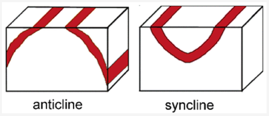
In map view, an anticline appears as parallel beds of the same rock type that dip away from the center of the fold. In an anticline, the oldest beds, the ones that were originally underneath the other beds, are at the center, along the axis of the fold. The axis is an imaginary line that marks the center of the fold on the map.
In map view, a syncline appears as a set of parallel beds that dip toward the center. In a syncline the youngest beds, the ones that were originally on top of the rest of the beds, are at the center, along the axis of the fold.
Anticlines and synclines form in sections of the crust that are undergoing compression, places where the crust is being pushed together.
Plunging Anticlines and Synclines
A plunging anticline or a plunging syncline is one that has its axis tilted from the horizontal so that the fold is plunging into the earth along its length. Plunge direction is the direction in which the axis of the fold tilts down into the earth.
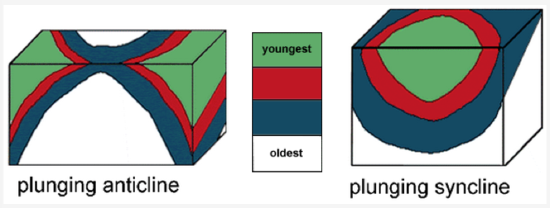
In map view, a plunging anticline makes a U-shaped or V-shaped pattern that points, or closes, in the direction of plunge. A cross-section at a right angle to the axis of a plunging anticline looks the same as an anticline.
In map view, a plunging syncline makes a U-shaped or V-shaped pattern that opens in the direction of plunge.
Basins and Domes
A basin is a bowl-like depression in the strata (layers of rock). A basin is similar to a syncline, but instead of an axis it has a single point at the center. The strata all dip toward the center point and the youngest rock is at the center. In map view, the strata form concentric circles – a bull’s eye pattern – around the center point.
A dome is an bulge in strata. A dome is similar to an anticline, but instead of an axis it has a single point at the center. The strata all dip away from the center point and the oldest rock is at the center. In map view, the strata form concentric circles – a bull’s eye pattern – around the center point.
FAULTS
A fault is a planar surface within the earth, along which rocks have broken and slid. Faults are caused by elastic strain that culminates in brittle failure. The rocks on either side of a fault have shifted in opposite directions, called the offset directions. If a fault is not vertical, there are rocks above the fault and rocks beneath the fault.
The rocks above a fault are called the hanging wall.
The rocks beneath a fault are called the footwall.
Normal and Detachment Faults
In a normal fault, the hanging wall has moved down relative to the footwall.
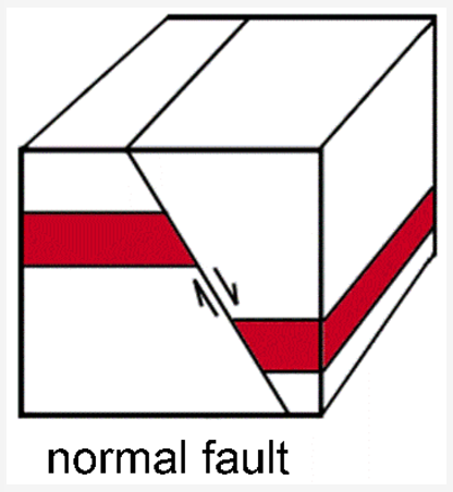
A detachment fault is a particular kind of normal fault that generally dips at a low angle. It separates rocks that were deep in the crust and ductile (granite and gneiss) from rocks of the upper crust (sedimentary or volcanic) that were brittle. Detachment faults occur along the boundaries of metamorphic core complexes (see below).
Normal and detachment faults form in sections of the crust that are undergoing tension, places where the crust is being stretched apart. A divergent plate boundary is a zone of large normal faults. Normal faults also occur in other zones of crustal tension, such as in the Basin and Range landscape region of the western United States.
Reverse and Thrust Faults
In a reverse or thrust fault, the hanging wall has moved up relative to the footwall. The difference between a reverse fault and a thrust fault is that a reverse fault has a steeper dip, more than 30°.
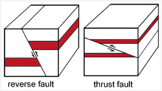
Reverse and thrust faults form in sections of the crust that are undergoing compression. A convergent plate boundary is a zone of major reverse and thrust faults. In fact, subduction zones are sometimes referred to as mega-thrust faults. Reverse and thrust faults also occur in other settings where the crust is being compressed, such as the Transverse Mountain Ranges, just north of Los Angeles.
Strike-Slip Faults
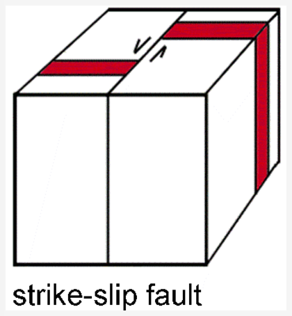
Strike-slip faults are steep or vertical faults along which the rocks on either side have moved horizontally in opposite directions. A transform plate boundary is a zone of large strike-slip faults. The San Andreas fault is an example of a major strike-slip fault at a transform boundary. Strike-slip faults also occur in other settings.
REFLECTION QUESTIONS
- What skill does this content help you develop?
- What are the key topics covered in this content?
- How can the content in this section help you demonstrate mastery of a specific skill?
- What questions do you have about this content?
Contributors and Attributions
Original content from Kimberly Schulte (Columbia Basin College) and supplemented by Lumen Learning. The content on this page is copyrighted under a Creative Commons Attribution 4.0 International license.


