6.1.3: Compressor Stations
- Page ID
- 15660
\( \newcommand{\vecs}[1]{\overset { \scriptstyle \rightharpoonup} {\mathbf{#1}} } \)
\( \newcommand{\vecd}[1]{\overset{-\!-\!\rightharpoonup}{\vphantom{a}\smash {#1}}} \)
\( \newcommand{\id}{\mathrm{id}}\) \( \newcommand{\Span}{\mathrm{span}}\)
( \newcommand{\kernel}{\mathrm{null}\,}\) \( \newcommand{\range}{\mathrm{range}\,}\)
\( \newcommand{\RealPart}{\mathrm{Re}}\) \( \newcommand{\ImaginaryPart}{\mathrm{Im}}\)
\( \newcommand{\Argument}{\mathrm{Arg}}\) \( \newcommand{\norm}[1]{\| #1 \|}\)
\( \newcommand{\inner}[2]{\langle #1, #2 \rangle}\)
\( \newcommand{\Span}{\mathrm{span}}\)
\( \newcommand{\id}{\mathrm{id}}\)
\( \newcommand{\Span}{\mathrm{span}}\)
\( \newcommand{\kernel}{\mathrm{null}\,}\)
\( \newcommand{\range}{\mathrm{range}\,}\)
\( \newcommand{\RealPart}{\mathrm{Re}}\)
\( \newcommand{\ImaginaryPart}{\mathrm{Im}}\)
\( \newcommand{\Argument}{\mathrm{Arg}}\)
\( \newcommand{\norm}[1]{\| #1 \|}\)
\( \newcommand{\inner}[2]{\langle #1, #2 \rangle}\)
\( \newcommand{\Span}{\mathrm{span}}\) \( \newcommand{\AA}{\unicode[.8,0]{x212B}}\)
\( \newcommand{\vectorA}[1]{\vec{#1}} % arrow\)
\( \newcommand{\vectorAt}[1]{\vec{\text{#1}}} % arrow\)
\( \newcommand{\vectorB}[1]{\overset { \scriptstyle \rightharpoonup} {\mathbf{#1}} } \)
\( \newcommand{\vectorC}[1]{\textbf{#1}} \)
\( \newcommand{\vectorD}[1]{\overrightarrow{#1}} \)
\( \newcommand{\vectorDt}[1]{\overrightarrow{\text{#1}}} \)
\( \newcommand{\vectE}[1]{\overset{-\!-\!\rightharpoonup}{\vphantom{a}\smash{\mathbf {#1}}}} \)
\( \newcommand{\vecs}[1]{\overset { \scriptstyle \rightharpoonup} {\mathbf{#1}} } \)
\( \newcommand{\vecd}[1]{\overset{-\!-\!\rightharpoonup}{\vphantom{a}\smash {#1}}} \)
\(\newcommand{\avec}{\mathbf a}\) \(\newcommand{\bvec}{\mathbf b}\) \(\newcommand{\cvec}{\mathbf c}\) \(\newcommand{\dvec}{\mathbf d}\) \(\newcommand{\dtil}{\widetilde{\mathbf d}}\) \(\newcommand{\evec}{\mathbf e}\) \(\newcommand{\fvec}{\mathbf f}\) \(\newcommand{\nvec}{\mathbf n}\) \(\newcommand{\pvec}{\mathbf p}\) \(\newcommand{\qvec}{\mathbf q}\) \(\newcommand{\svec}{\mathbf s}\) \(\newcommand{\tvec}{\mathbf t}\) \(\newcommand{\uvec}{\mathbf u}\) \(\newcommand{\vvec}{\mathbf v}\) \(\newcommand{\wvec}{\mathbf w}\) \(\newcommand{\xvec}{\mathbf x}\) \(\newcommand{\yvec}{\mathbf y}\) \(\newcommand{\zvec}{\mathbf z}\) \(\newcommand{\rvec}{\mathbf r}\) \(\newcommand{\mvec}{\mathbf m}\) \(\newcommand{\zerovec}{\mathbf 0}\) \(\newcommand{\onevec}{\mathbf 1}\) \(\newcommand{\real}{\mathbb R}\) \(\newcommand{\twovec}[2]{\left[\begin{array}{r}#1 \\ #2 \end{array}\right]}\) \(\newcommand{\ctwovec}[2]{\left[\begin{array}{c}#1 \\ #2 \end{array}\right]}\) \(\newcommand{\threevec}[3]{\left[\begin{array}{r}#1 \\ #2 \\ #3 \end{array}\right]}\) \(\newcommand{\cthreevec}[3]{\left[\begin{array}{c}#1 \\ #2 \\ #3 \end{array}\right]}\) \(\newcommand{\fourvec}[4]{\left[\begin{array}{r}#1 \\ #2 \\ #3 \\ #4 \end{array}\right]}\) \(\newcommand{\cfourvec}[4]{\left[\begin{array}{c}#1 \\ #2 \\ #3 \\ #4 \end{array}\right]}\) \(\newcommand{\fivevec}[5]{\left[\begin{array}{r}#1 \\ #2 \\ #3 \\ #4 \\ #5 \\ \end{array}\right]}\) \(\newcommand{\cfivevec}[5]{\left[\begin{array}{c}#1 \\ #2 \\ #3 \\ #4 \\ #5 \\ \end{array}\right]}\) \(\newcommand{\mattwo}[4]{\left[\begin{array}{rr}#1 \amp #2 \\ #3 \amp #4 \\ \end{array}\right]}\) \(\newcommand{\laspan}[1]{\text{Span}\{#1\}}\) \(\newcommand{\bcal}{\cal B}\) \(\newcommand{\ccal}{\cal C}\) \(\newcommand{\scal}{\cal S}\) \(\newcommand{\wcal}{\cal W}\) \(\newcommand{\ecal}{\cal E}\) \(\newcommand{\coords}[2]{\left\{#1\right\}_{#2}}\) \(\newcommand{\gray}[1]{\color{gray}{#1}}\) \(\newcommand{\lgray}[1]{\color{lightgray}{#1}}\) \(\newcommand{\rank}{\operatorname{rank}}\) \(\newcommand{\row}{\text{Row}}\) \(\newcommand{\col}{\text{Col}}\) \(\renewcommand{\row}{\text{Row}}\) \(\newcommand{\nul}{\text{Nul}}\) \(\newcommand{\var}{\text{Var}}\) \(\newcommand{\corr}{\text{corr}}\) \(\newcommand{\len}[1]{\left|#1\right|}\) \(\newcommand{\bbar}{\overline{\bvec}}\) \(\newcommand{\bhat}{\widehat{\bvec}}\) \(\newcommand{\bperp}{\bvec^\perp}\) \(\newcommand{\xhat}{\widehat{\xvec}}\) \(\newcommand{\vhat}{\widehat{\vvec}}\) \(\newcommand{\uhat}{\widehat{\uvec}}\) \(\newcommand{\what}{\widehat{\wvec}}\) \(\newcommand{\Sighat}{\widehat{\Sigma}}\) \(\newcommand{\lt}{<}\) \(\newcommand{\gt}{>}\) \(\newcommand{\amp}{&}\) \(\definecolor{fillinmathshade}{gray}{0.9}\)Please watch this video about how a compressor station works.
How a compressor station works (3:59)
Components of a Compressor Station
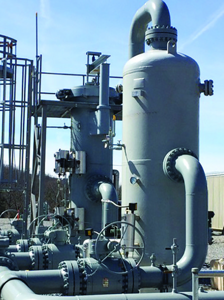
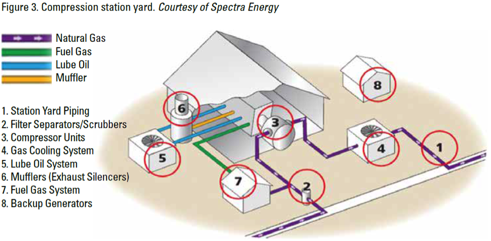
Natural gas enters a compressor station through station yard piping and is passed through scrubbers and filters to extract any liquids and remove solids or other particulate matter that may be in the gas stream (Figure 3). Once the natural gas stream has been cleaned, it is directed through additional yard piping to individual compressors. Computers regulate the flow and number of units that are needed to handle the scheduled system flow requirements. Most compressor units operate in parallel, with the individual compressor units providing the needed additional pressure, before directing the gas back into the pipeline with full operational pressure restored. When the required boost in pressure is very high, several compressor units may be operated in stages (serially) to achieve the desired pressure in stages.

National Fuel Gas Midstream Corporation
Compressor stations are an integral part of the natural gas pipeline network that moves natural gas from individual producing well sites to end users. As natural gas moves through a pipeline, distance, friction, and elevation differences slow the movement of the gas, and reduce pressure. Compressor stations are placed strategically within the gathering and transportation pipeline network to help maintain the pressure and flow of gas to market.

Penn State Extension
As natural gas is compressed, heat is generated and must be dissipated to cool the gas stream before leaving the compressor facility. For every 100 psi increase in pressure, the temperature of the gas stream increases by 7–8 degrees. Most compressor stations have an aerial cooler system to dissipate excess heat (an “after” cooler). The heat generated by the operation of the individual compressor units is dissipated via a sealed coolant system similar to an automotive radiator.
In wet gas areas, or areas that produce natural gas liquids (NGLs), changes in pressure and temperature cause some of the liquids to drop out. The liquids that drop out are captured in tanks and trucked off site. The liquids captured are called natural gasoline or drip gas, which is often used as a blend in motor gasoline.
Most compressor stations are fueled by a portion of the natural gas flowing through the station, although in some areas of the country, all or some of the units may be electrically powered primarily for environmental or security reasons. Gas-powered compressors may be driven by either conventional piston engines or natural gas turbine units. There are site design and operational differences, as well as unique air and sound emissions, between these competing compressor engine technologies.
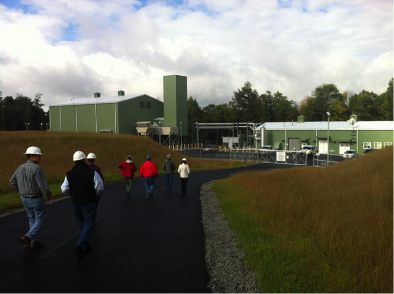
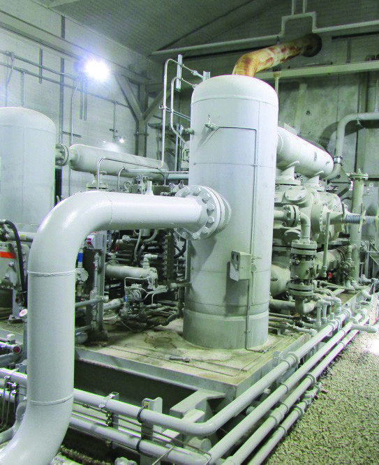
There may be one or more individual compressor units at a station, which can be out in the open, or more often, housed in a building to facilitate maintenance and sound management. Newer units are often housed one per building, but there may be multiple units in one large building. Compressor buildings generally incorporate insulated walls, shielded exhaust systems, and advanced fan technology to dampen sound. Newly constructed compressor buildings may incorporate these features where local, state, or federal regulations require noise mitigation.

Penn State Extension, Marcellus Education Team
Compressor station yards for gathering lines are often larger than transmission line compressors due to multiple pipelines coming into the complex, and sometimes, additional equipment needed to filter and remove liquids from the gas stream. Other components of a compressor complex include backup generators, gas metering equipment, gas filtration systems, and system monitoring and safety controls. There may also be odorization equipment to add mercaptan, which provides the distinctive sulfurous odor to natural gas.

Courtesy of Spectra Energy
Please refer to Penn State Extension Publication ‘Understanding Natural Gas Compressor Stations’ to learn more about the types of compressor stations, regulatory oversight, safety and landowner and community considerations.
Required Reading
Check Your Understanding
Why are compressor stations an integral part of the natural gas pipeline network?
- Answer
-
Compressor stations are an integral part of the natural gas pipeline network that moves natural gas from individual producing well sites to end users. As natural gas moves through a pipeline, distance, friction, and elevation differences slow the movement of the gas, and reduce pressure. Compressor stations are placed strategically within the gathering and transportation pipeline network to help maintain the pressure and flow of gas to market.


