Turbidites
- Page ID
- 10909
\( \newcommand{\vecs}[1]{\overset { \scriptstyle \rightharpoonup} {\mathbf{#1}} } \)
\( \newcommand{\vecd}[1]{\overset{-\!-\!\rightharpoonup}{\vphantom{a}\smash {#1}}} \)
\( \newcommand{\dsum}{\displaystyle\sum\limits} \)
\( \newcommand{\dint}{\displaystyle\int\limits} \)
\( \newcommand{\dlim}{\displaystyle\lim\limits} \)
\( \newcommand{\id}{\mathrm{id}}\) \( \newcommand{\Span}{\mathrm{span}}\)
( \newcommand{\kernel}{\mathrm{null}\,}\) \( \newcommand{\range}{\mathrm{range}\,}\)
\( \newcommand{\RealPart}{\mathrm{Re}}\) \( \newcommand{\ImaginaryPart}{\mathrm{Im}}\)
\( \newcommand{\Argument}{\mathrm{Arg}}\) \( \newcommand{\norm}[1]{\| #1 \|}\)
\( \newcommand{\inner}[2]{\langle #1, #2 \rangle}\)
\( \newcommand{\Span}{\mathrm{span}}\)
\( \newcommand{\id}{\mathrm{id}}\)
\( \newcommand{\Span}{\mathrm{span}}\)
\( \newcommand{\kernel}{\mathrm{null}\,}\)
\( \newcommand{\range}{\mathrm{range}\,}\)
\( \newcommand{\RealPart}{\mathrm{Re}}\)
\( \newcommand{\ImaginaryPart}{\mathrm{Im}}\)
\( \newcommand{\Argument}{\mathrm{Arg}}\)
\( \newcommand{\norm}[1]{\| #1 \|}\)
\( \newcommand{\inner}[2]{\langle #1, #2 \rangle}\)
\( \newcommand{\Span}{\mathrm{span}}\) \( \newcommand{\AA}{\unicode[.8,0]{x212B}}\)
\( \newcommand{\vectorA}[1]{\vec{#1}} % arrow\)
\( \newcommand{\vectorAt}[1]{\vec{\text{#1}}} % arrow\)
\( \newcommand{\vectorB}[1]{\overset { \scriptstyle \rightharpoonup} {\mathbf{#1}} } \)
\( \newcommand{\vectorC}[1]{\textbf{#1}} \)
\( \newcommand{\vectorD}[1]{\overrightarrow{#1}} \)
\( \newcommand{\vectorDt}[1]{\overrightarrow{\text{#1}}} \)
\( \newcommand{\vectE}[1]{\overset{-\!-\!\rightharpoonup}{\vphantom{a}\smash{\mathbf {#1}}}} \)
\( \newcommand{\vecs}[1]{\overset { \scriptstyle \rightharpoonup} {\mathbf{#1}} } \)
\(\newcommand{\longvect}{\overrightarrow}\)
\( \newcommand{\vecd}[1]{\overset{-\!-\!\rightharpoonup}{\vphantom{a}\smash {#1}}} \)
\(\newcommand{\avec}{\mathbf a}\) \(\newcommand{\bvec}{\mathbf b}\) \(\newcommand{\cvec}{\mathbf c}\) \(\newcommand{\dvec}{\mathbf d}\) \(\newcommand{\dtil}{\widetilde{\mathbf d}}\) \(\newcommand{\evec}{\mathbf e}\) \(\newcommand{\fvec}{\mathbf f}\) \(\newcommand{\nvec}{\mathbf n}\) \(\newcommand{\pvec}{\mathbf p}\) \(\newcommand{\qvec}{\mathbf q}\) \(\newcommand{\svec}{\mathbf s}\) \(\newcommand{\tvec}{\mathbf t}\) \(\newcommand{\uvec}{\mathbf u}\) \(\newcommand{\vvec}{\mathbf v}\) \(\newcommand{\wvec}{\mathbf w}\) \(\newcommand{\xvec}{\mathbf x}\) \(\newcommand{\yvec}{\mathbf y}\) \(\newcommand{\zvec}{\mathbf z}\) \(\newcommand{\rvec}{\mathbf r}\) \(\newcommand{\mvec}{\mathbf m}\) \(\newcommand{\zerovec}{\mathbf 0}\) \(\newcommand{\onevec}{\mathbf 1}\) \(\newcommand{\real}{\mathbb R}\) \(\newcommand{\twovec}[2]{\left[\begin{array}{r}#1 \\ #2 \end{array}\right]}\) \(\newcommand{\ctwovec}[2]{\left[\begin{array}{c}#1 \\ #2 \end{array}\right]}\) \(\newcommand{\threevec}[3]{\left[\begin{array}{r}#1 \\ #2 \\ #3 \end{array}\right]}\) \(\newcommand{\cthreevec}[3]{\left[\begin{array}{c}#1 \\ #2 \\ #3 \end{array}\right]}\) \(\newcommand{\fourvec}[4]{\left[\begin{array}{r}#1 \\ #2 \\ #3 \\ #4 \end{array}\right]}\) \(\newcommand{\cfourvec}[4]{\left[\begin{array}{c}#1 \\ #2 \\ #3 \\ #4 \end{array}\right]}\) \(\newcommand{\fivevec}[5]{\left[\begin{array}{r}#1 \\ #2 \\ #3 \\ #4 \\ #5 \\ \end{array}\right]}\) \(\newcommand{\cfivevec}[5]{\left[\begin{array}{c}#1 \\ #2 \\ #3 \\ #4 \\ #5 \\ \end{array}\right]}\) \(\newcommand{\mattwo}[4]{\left[\begin{array}{rr}#1 \amp #2 \\ #3 \amp #4 \\ \end{array}\right]}\) \(\newcommand{\laspan}[1]{\text{Span}\{#1\}}\) \(\newcommand{\bcal}{\cal B}\) \(\newcommand{\ccal}{\cal C}\) \(\newcommand{\scal}{\cal S}\) \(\newcommand{\wcal}{\cal W}\) \(\newcommand{\ecal}{\cal E}\) \(\newcommand{\coords}[2]{\left\{#1\right\}_{#2}}\) \(\newcommand{\gray}[1]{\color{gray}{#1}}\) \(\newcommand{\lgray}[1]{\color{lightgray}{#1}}\) \(\newcommand{\rank}{\operatorname{rank}}\) \(\newcommand{\row}{\text{Row}}\) \(\newcommand{\col}{\text{Col}}\) \(\renewcommand{\row}{\text{Row}}\) \(\newcommand{\nul}{\text{Nul}}\) \(\newcommand{\var}{\text{Var}}\) \(\newcommand{\corr}{\text{corr}}\) \(\newcommand{\len}[1]{\left|#1\right|}\) \(\newcommand{\bbar}{\overline{\bvec}}\) \(\newcommand{\bhat}{\widehat{\bvec}}\) \(\newcommand{\bperp}{\bvec^\perp}\) \(\newcommand{\xhat}{\widehat{\xvec}}\) \(\newcommand{\vhat}{\widehat{\vvec}}\) \(\newcommand{\uhat}{\widehat{\uvec}}\) \(\newcommand{\what}{\widehat{\wvec}}\) \(\newcommand{\Sighat}{\widehat{\Sigma}}\) \(\newcommand{\lt}{<}\) \(\newcommand{\gt}{>}\) \(\newcommand{\amp}{&}\) \(\definecolor{fillinmathshade}{gray}{0.9}\)Introduction
You're likely familiar with the process of landslides. In bodies of water, a similar process occurs and produces turbidites. Turbidites are deposited from slurries of sediment and water in any standing body of water (lakes, oceans). They can occur in any layer of a water body (near surface, benthic) as long as there is an oversteepened slope. The fluid involved is water, which mixes with sediment. The new sediment and water mixture is denser than the surrounding water. Turbidites are commonly seen with other sedimentary structures such as ripple lamination, sole marks, and flame structures.
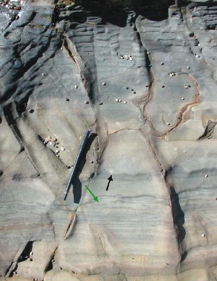
Figure \(\PageIndex{1}\): Turbidites deposited on a submarine fan in the Cretaceous Pigeon Point Formation (Pebble Beach near Pescadero, CA). An erosional surface (black arrow) is overlain by a normally graded bed. Ripple lamination is visible in a lower bed (green arrow). (© 2003 Dawn Y. Sumner)
Sediment Transport Processes
Now that we have a better grasp of what a turbidite is, let's look at a step by step outline of how they occur.
- Turbidity flows start with slope failure in soft sediment. Slopes become oversteepened where sedimentation rates are very high, such at the mouths of rivers. Because flow speeds are very low in standing water, the sediment does not get washed down slope. Rather, it builds up until there is subaqueous slope failure. Earthquakes are common triggers for these slides.
- Sediment and water mix creating a “fluid” that is denser than the surrounding water because of the entrained sediment. Thus, it flows downhill even if the slope is very low (1°).
- The base of the flow is commonly erosional on steep slopes, so even more sediment is entrained in the flow.
- Enough sediment is entrained that erosion stops. Deposition begins as the slope gets shallower or the flow starts to slow down. Initially, the coarsest grains are deposited (remember the Hjulstrom diagram) and then finer grains, so the sediment is “graded”. However, the sediment is usually poorly sorted because the flow is a slurry of water and sediment so hydraulic sorting is reduced. (Facies = Bouma a)
- Sediment concentration decreases with deposition, so one gets more hydraulic sorting. The flow is very fast so the sediment has upper planar lamination. (Facies = Bouma b)
- As the flow slows more, grain size decreases and ripples start to form. Dunes do not usually form for two reasons: a) often only fine sand and finer grains are left in the flow by this point; and b) dunes do not have time to develop. (Facies = Bouma c)
- Eventually, the flow slows to the point that bedload transport stops and deposition is mostly settling of silt and then clay. The progressive settling of coarser and then finer grains produces a faint lamination, but it is not as strong as the planar laminations in Bouma b. (Facies = Bouma d)
- Mud settles out producing shale. This can look identical to background settling of clays brought into the lake/ocean as suspended sediment. (Facies = Bouma e)
Bouma divisions a-d can take hours or a day or so to be deposited. However, division e, which is usually the thinnest, commonly accumulates over months or longer (e.g. hundreds of years) depending on how frequent turbidites are in the area.
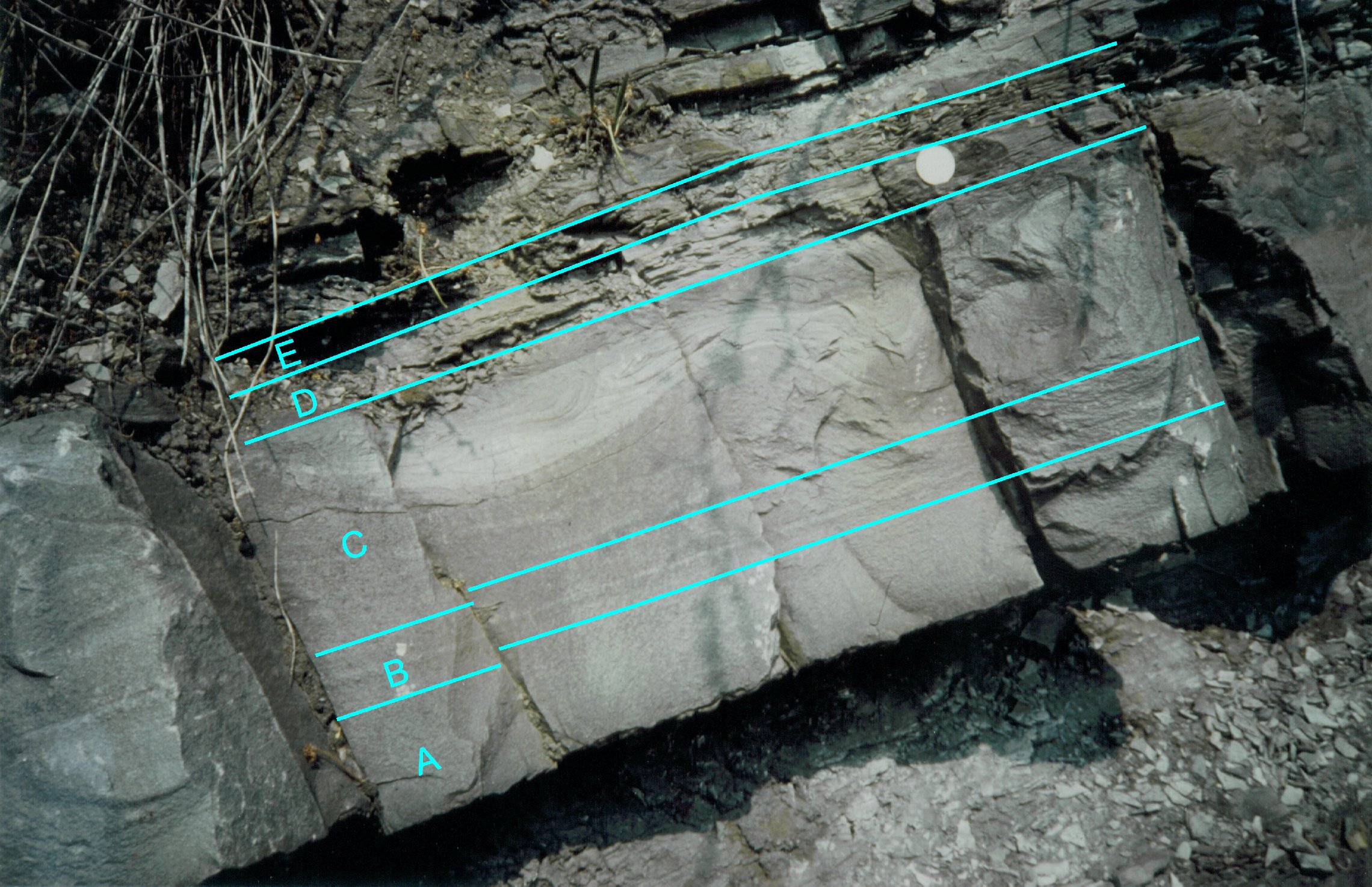
Figure \(\PageIndex{2}\): Complete Bouma sequence (a-e) in Devonian Sandstone in Becke-Oese Quarry, Germany (CC BY-SA 3.0; Jo Weber via Wikimedia)
So how do turbidites look in action? For obvious reasons, it is difficult to record a turbidite on camera, but the below video was fortuitously filmed by underwater equipment in Mendocino Canyon off the coast of California (see Sumner and Paull, 2014, for a full description).
It is important to note that the parts of turbidites that are deposited change down slope and usually only a few of the subdivisions are preserved. In the most proximal (up slope) environments, divisions a and b are most common. In the more distal areas, all of the coarser sediment has already been deposited upstream, so divisions d and e are most common. Generally, there are also channels which fan out producing variations in rock types that change in space and through time.
Characteristics of Deposited Sediment
The most common sedimentary structures associated with turbidites are current ripple cross laminations, flame structures, sole marks, planar laminations, and contorted ripple laminae. The below pictures should give you a better idea of what these structures look like in the field.
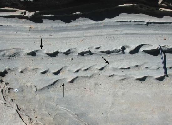
Figure \(\PageIndex{3}\): Flame structures formed where turbidites were deposited over shaley layers in the Cretaceous Pigeon Point Formation. (© 2003 Dawn Y. Sumner)
For a quick refresh, flame structures are deformation in soft sediments that form in unconsolidated sediments that are usually saturated with water. When an overlying bed becomes too heavy, it forces the bed below it to push up though the overlying bed, creating a rounded wavy pattern that resembles flames.
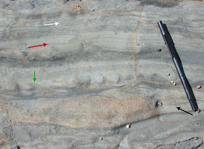
Figure \(\PageIndex{4}\): These turbidites show faint current ripple cross laminations (black arrow), flame structures (green arrow), planar laminations (red arrow), and possible contorted ripple laminae (white arrow). Photo taken in the Cretaceous Pigeon Point Formation (© 2003 Dawn Y. Sumner)
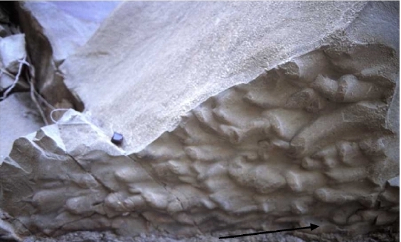
Figure \(\PageIndex{5}\): Cretaceous Sole Marks in Cache Creek, CA. Black arrow indicates direction of paleocurrent (© 2001 Dawn Y. Sumner)
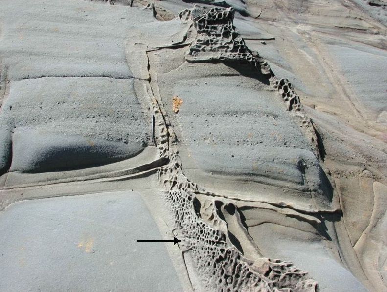
Figure \(\PageIndex{6}\): Coarse sand to pebble cross stratification filling a submarine channel fan in the Cretaceous Pigeon Point Formation. The pitted weathering (black arrow) is due to differential cementation and reflects diagenetic processes rather than depositional processes.
As the turbidite facies is a very high energy environment, there is usually few fossils or biotubation activity. However, there is generally some degree of bioturbation in Bouma e, though this is not a defining characteristic of turbidite facies.
Typical Vertical Sequence of Facies Representing This Environment
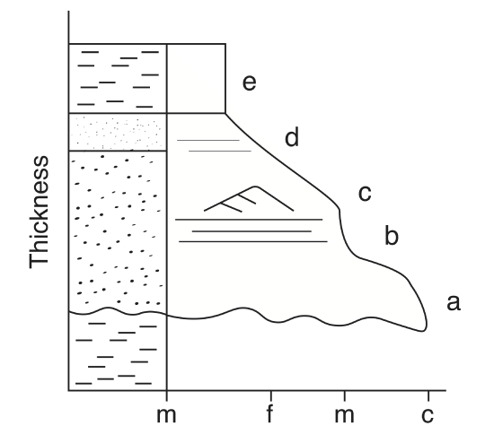
Figure \(\PageIndex{7}\): A model of the Bouma sequence (Created by Taryn Lausch)
As we can see from the figure, the expected succession of rocks we would see from this environment are mudstone, coarser grained sandstone, finer grained sandstone, siltstone, and finally mudstone again. The rocks fine upward as the flow slows, resulting in the bouma sequence.
The wavy line at the base of Bouma a in Figure 7 indicates an erosional surface, and flute casts or scour marks are sometimes present. As the flow slows down, it is no longer erosional, and larger sediments (coarse sand) begin to be deposited in Bouma a. As the flow is still moving rather quickly at the point, the sandstone deposited in Bouma a is usually massive. Moving to Bouma b, the flow continues to slow down, there is less turbulence, and grain size continues to fine, allowing for the formation of upper planar lamination. The flow slows down more in Bouma c, depositing even finer grained sandstone, and you begin to see current ripples. In Bouma d, the flow is very slow moving, and silt settles out of suspension as opposed to being part of the bed load. Faint planar lamination can be seen in Bouma d, and can be confused for the planar lamination on Bouma b, however the lamination in Bouma d are usually not as well defined. Eventually, the flow stops and the water is still again, allowing for the accumulation of mud and the preparation for the next turbidite flow.
The difficulty in recognizing turbidite stratigraphy is that not all of the parts of the Bouma sequence will be clearly distinguishable, particularly the faint planar lamination of Bouma d. Not all parts of the sequence will be preserved, perhaps just the ripple marks and some flame structures. It is helpful to use the key parts of the sequence such as the upward fining trend, planar laminations and sole marks or flame stuctures to distinguish a turbidite. It is also important to note that the vertical sequence is an accumulation of multiple turbidite events. A single turbidite flow will leave behind the Bouma sequence with Bouma a closer to the failure point and Bouma e furthest
away.
A small sidenote about the history of turbidite discovery: Turbidite flows were initially controversial because a process that resulted in the bouma sequence had not been observed in modern depositional environments. Many geologists did not believe that you could generate strong enough currents underwater to get those flow characteristics. Eventually in 1964, two geologists Bruce Heezen and Avery Drake realized that an event in 1929 provided strong evidence for turbidity currents. In 1929, which is long before there were satellites, under water telegraph cables were strung from Newfoundland to Europe. In November, about 30 cables broke in order from farthest north and shallowest to farther south and deeper water. At the time, people did not know why they broke, but Heezen and Drake suggested that a turbidity current was triggered by an earthquake and the cables broke as the turbidity current passed over them (they are strong flows!). Because they were continuously used for communication, the time each cable broke was precisely known. Heezen and Drake calculated that the front of the flow traveled at 250 km/h (36,000 cm/s) when the turbidite first formed and then slowed to around 20 km/h (7000 cm/s) by the time the last cables broke 500 km from the source. This was a fast, strong flow and may be typical of turbidites. These flow speeds are very erosive. It is only after the turbidite slows down even more that you get deposition. The characteristics of the flow seen by the breaking cables fit the flow characteristics proposed by the sedimentologists, and now turbidity currents and the facies model developed for turbidites are widely accepted and often treated as a good example of rocks that closely reflect flow characteristics.
Summary
Turbidites are subaqueous flows that begin with a slope failure. As sediment builds up and the slope gets steeper and steeper, and earthquake or simply oversteepening of the slope can cause a submarine debris flow, ie a turbidity current. This flow extends down the slope with a dense mixture of sediment and water. As the slope decreases, the flow slows down and sediments begin to be deposited. Turbidites all have the same flow characteristics consisting of a very strong erosive flow, deposition of a normally graded bed that is massive, followed by upper plane bedding, rippled finer sands, coarsely laminated silts, then shales.
Keywords:
- bouma sequence
- sole marks
- flame structures
- upward fining
- planar lamination
- current ripple cross laminations


