7.3.3: Base Isolation
- Page ID
- 6274
\( \newcommand{\vecs}[1]{\overset { \scriptstyle \rightharpoonup} {\mathbf{#1}} } \)
\( \newcommand{\vecd}[1]{\overset{-\!-\!\rightharpoonup}{\vphantom{a}\smash {#1}}} \)
\( \newcommand{\id}{\mathrm{id}}\) \( \newcommand{\Span}{\mathrm{span}}\)
( \newcommand{\kernel}{\mathrm{null}\,}\) \( \newcommand{\range}{\mathrm{range}\,}\)
\( \newcommand{\RealPart}{\mathrm{Re}}\) \( \newcommand{\ImaginaryPart}{\mathrm{Im}}\)
\( \newcommand{\Argument}{\mathrm{Arg}}\) \( \newcommand{\norm}[1]{\| #1 \|}\)
\( \newcommand{\inner}[2]{\langle #1, #2 \rangle}\)
\( \newcommand{\Span}{\mathrm{span}}\)
\( \newcommand{\id}{\mathrm{id}}\)
\( \newcommand{\Span}{\mathrm{span}}\)
\( \newcommand{\kernel}{\mathrm{null}\,}\)
\( \newcommand{\range}{\mathrm{range}\,}\)
\( \newcommand{\RealPart}{\mathrm{Re}}\)
\( \newcommand{\ImaginaryPart}{\mathrm{Im}}\)
\( \newcommand{\Argument}{\mathrm{Arg}}\)
\( \newcommand{\norm}[1]{\| #1 \|}\)
\( \newcommand{\inner}[2]{\langle #1, #2 \rangle}\)
\( \newcommand{\Span}{\mathrm{span}}\) \( \newcommand{\AA}{\unicode[.8,0]{x212B}}\)
\( \newcommand{\vectorA}[1]{\vec{#1}} % arrow\)
\( \newcommand{\vectorAt}[1]{\vec{\text{#1}}} % arrow\)
\( \newcommand{\vectorB}[1]{\overset { \scriptstyle \rightharpoonup} {\mathbf{#1}} } \)
\( \newcommand{\vectorC}[1]{\textbf{#1}} \)
\( \newcommand{\vectorD}[1]{\overrightarrow{#1}} \)
\( \newcommand{\vectorDt}[1]{\overrightarrow{\text{#1}}} \)
\( \newcommand{\vectE}[1]{\overset{-\!-\!\rightharpoonup}{\vphantom{a}\smash{\mathbf {#1}}}} \)
\( \newcommand{\vecs}[1]{\overset { \scriptstyle \rightharpoonup} {\mathbf{#1}} } \)
\( \newcommand{\vecd}[1]{\overset{-\!-\!\rightharpoonup}{\vphantom{a}\smash {#1}}} \)
\(\newcommand{\avec}{\mathbf a}\) \(\newcommand{\bvec}{\mathbf b}\) \(\newcommand{\cvec}{\mathbf c}\) \(\newcommand{\dvec}{\mathbf d}\) \(\newcommand{\dtil}{\widetilde{\mathbf d}}\) \(\newcommand{\evec}{\mathbf e}\) \(\newcommand{\fvec}{\mathbf f}\) \(\newcommand{\nvec}{\mathbf n}\) \(\newcommand{\pvec}{\mathbf p}\) \(\newcommand{\qvec}{\mathbf q}\) \(\newcommand{\svec}{\mathbf s}\) \(\newcommand{\tvec}{\mathbf t}\) \(\newcommand{\uvec}{\mathbf u}\) \(\newcommand{\vvec}{\mathbf v}\) \(\newcommand{\wvec}{\mathbf w}\) \(\newcommand{\xvec}{\mathbf x}\) \(\newcommand{\yvec}{\mathbf y}\) \(\newcommand{\zvec}{\mathbf z}\) \(\newcommand{\rvec}{\mathbf r}\) \(\newcommand{\mvec}{\mathbf m}\) \(\newcommand{\zerovec}{\mathbf 0}\) \(\newcommand{\onevec}{\mathbf 1}\) \(\newcommand{\real}{\mathbb R}\) \(\newcommand{\twovec}[2]{\left[\begin{array}{r}#1 \\ #2 \end{array}\right]}\) \(\newcommand{\ctwovec}[2]{\left[\begin{array}{c}#1 \\ #2 \end{array}\right]}\) \(\newcommand{\threevec}[3]{\left[\begin{array}{r}#1 \\ #2 \\ #3 \end{array}\right]}\) \(\newcommand{\cthreevec}[3]{\left[\begin{array}{c}#1 \\ #2 \\ #3 \end{array}\right]}\) \(\newcommand{\fourvec}[4]{\left[\begin{array}{r}#1 \\ #2 \\ #3 \\ #4 \end{array}\right]}\) \(\newcommand{\cfourvec}[4]{\left[\begin{array}{c}#1 \\ #2 \\ #3 \\ #4 \end{array}\right]}\) \(\newcommand{\fivevec}[5]{\left[\begin{array}{r}#1 \\ #2 \\ #3 \\ #4 \\ #5 \\ \end{array}\right]}\) \(\newcommand{\cfivevec}[5]{\left[\begin{array}{c}#1 \\ #2 \\ #3 \\ #4 \\ #5 \\ \end{array}\right]}\) \(\newcommand{\mattwo}[4]{\left[\begin{array}{rr}#1 \amp #2 \\ #3 \amp #4 \\ \end{array}\right]}\) \(\newcommand{\laspan}[1]{\text{Span}\{#1\}}\) \(\newcommand{\bcal}{\cal B}\) \(\newcommand{\ccal}{\cal C}\) \(\newcommand{\scal}{\cal S}\) \(\newcommand{\wcal}{\cal W}\) \(\newcommand{\ecal}{\cal E}\) \(\newcommand{\coords}[2]{\left\{#1\right\}_{#2}}\) \(\newcommand{\gray}[1]{\color{gray}{#1}}\) \(\newcommand{\lgray}[1]{\color{lightgray}{#1}}\) \(\newcommand{\rank}{\operatorname{rank}}\) \(\newcommand{\row}{\text{Row}}\) \(\newcommand{\col}{\text{Col}}\) \(\renewcommand{\row}{\text{Row}}\) \(\newcommand{\nul}{\text{Nul}}\) \(\newcommand{\var}{\text{Var}}\) \(\newcommand{\corr}{\text{corr}}\) \(\newcommand{\len}[1]{\left|#1\right|}\) \(\newcommand{\bbar}{\overline{\bvec}}\) \(\newcommand{\bhat}{\widehat{\bvec}}\) \(\newcommand{\bperp}{\bvec^\perp}\) \(\newcommand{\xhat}{\widehat{\xvec}}\) \(\newcommand{\vhat}{\widehat{\vvec}}\) \(\newcommand{\uhat}{\widehat{\uvec}}\) \(\newcommand{\what}{\widehat{\wvec}}\) \(\newcommand{\Sighat}{\widehat{\Sigma}}\) \(\newcommand{\lt}{<}\) \(\newcommand{\gt}{>}\) \(\newcommand{\amp}{&}\) \(\definecolor{fillinmathshade}{gray}{0.9}\)Overview
The normal approach to providing seismic resistance is to attach the structure firmly to the ground. All ground movements are transferred to the structure, which is designed to survive the inertial forces of the ground motion. This is the reason why your house is bolted to its foundation and your cripple wall is reinforced.
In large buildings, these inertial forces can exceed the strength of any structure that has been reinforced within reasonable economic limits. The engineer designs the building to be highly ductile so that it will deform extensively and absorb these inertial forces without collapsing. Moment-resistant steel-frame structures are good for this purpose, as are special concrete structures with a large amount of steel reinforcing.

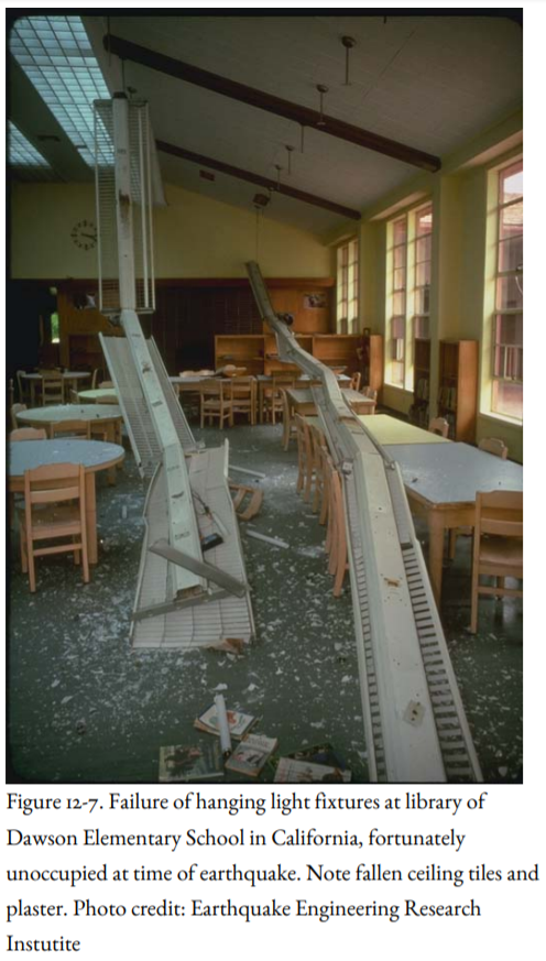
These buildings don’t collapse, but, as stated above, they have a major disadvantage. In deforming, they can cause extensive damage to ceilings, partitions, and building contents (Figure 12-7) such as filing cabinets and computers. Equipment, including utilities, will stop operating. High-rise buildings will sway and might cause occupants to become motion-sick and panicky. In addition, staircases may fail, hindering evacuation of the building after an earthquake.
The problem with attaching the building firmly to the ground is that the earthquake waves are absorbed by the building and its contents, often destructively. Is there a way to dissipate the energy in the foundation before it reaches the main floors of the building?
In base isolation, the engineer takes the opposite approach: the objective is to keep the ground motion from being transferred into the building. This is the same objective as in automobile design—to keep the passengers from feeling all the bumps in the road. To accomplish this, the automobile is designed with air-inflated tires, springs, and shock absorbers to keep its passengers comfortable.
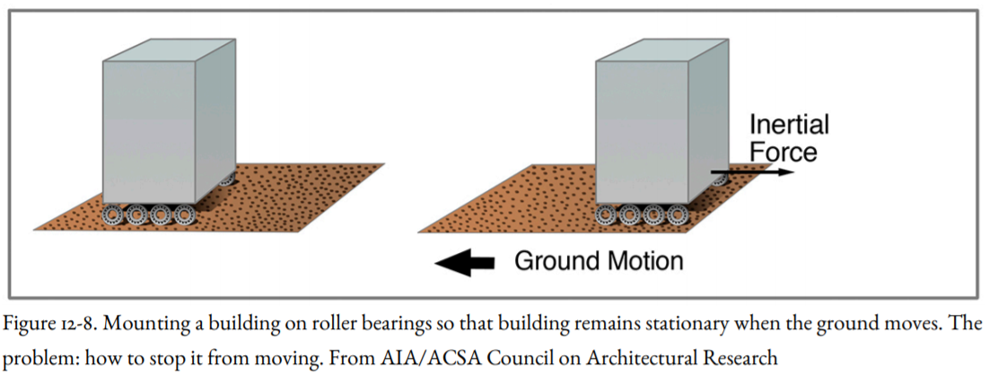
One way to do this is to put the building on roller bearings so that as the ground moves horizontally, the building remains stationary (Figure 12-8). A problem with this solution is that roller bearings would still transmit force into the building through friction. In addition, once the building began to roll, its inertia would tend to keep it moving. We need a structure that allows horizontal movement with respect to the ground, but restrains, or dampens, this movement so that as the ground vibrates rapidly, the building vibrates much more slowly with slower velocities and accelerations.

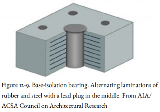
The solution is to separate the requirement for load-bearing (vertical loads) from that for movement (horizontal loads). One way to do this involves a lead-rubber bearing (Figure 12-9). This bearing consists of alternating laminations of rubber and steel, which allow for up to six inches of horizontal movement without fracturing but are strong enough to support the building. A cylindrical lead plug is placed in the center of this bearing to dampen the oscillations in the ground produced by an earthquake, just like the shock absorbers in a car. The energy of the earthquake waves is absorbed by the lead plug rather than by the building itself. The lead plugs do not deform in small earthquakes or high winds; in that respect, they serve as “seismic fuses.”

Lead recovers nearly all of its mechanical properties after each deformation from an earthquake. This is analogous to the solid-state ductile deformation of lower crustal rocks without producing earthquakes. The lead-rubber bearings allow the ground under a building to move rapidly, but the building itself moves much more slowly, thereby reducing accelerations and maximum shear forces applied to the building. The building is allowed to move about six inches horizontally. A six-inch slot around the building is built for this purpose and covered by a replaceable metal grating. The damage to architectural and mechanical components of the building, and the ensuing costly repairs are greatly reduced and, in some instances, almost eliminated.
There are some new systems, which go beyond the lead-bearing base isolator. Examples are the single and triple pendulum bearing systems. The single pendulum system maintains constant friction, lateral stiffness, and dynamic period for all levels of earthquake motion and displacements. The triple pendulum system includes three pendulum mechanisms that are sequentially activated as the earthquake motions become more intense.
Although base isolation adds to the cost of construction, some cost savings are possible within the building itself because so much of the earthquake force is absorbed at the base of the building rather than transmitted into the structure.
The Pioneer Courthouse in Portland, constructed in 1875, is the oldest surviving federal building in the Pacific Northwest, and it has been designated a National Historic Landmark. It houses the Ninth District Court of Appeals. The challenge of seismic retrofit of this unreinforced-masonry building was to strengthen the building without totally disrupting its character, including its sandstone-block walls. The solution was base isolation, installed below the existing foundations of the building, which minimized construction in the historic sections of the structure. The retrofit was completed in 2005.
Research is underway in Japan, New Zealand, and the United States to design other methods of base isolation and other ways to dissipate seismic energy in a building. After the 1989 Loma Prieta Earthquake, the California State Legislature passed Senate Bill 920, requiring the state architect to select one new and two existing buildings to demonstrate new engineering technologies, including base isolation. The new international airport terminal in Istanbul, Turkey, is the largest base-isolation building on Earth.


