3.6: Boundary Layers
- Page ID
- 4167
\( \newcommand{\vecs}[1]{\overset { \scriptstyle \rightharpoonup} {\mathbf{#1}} } \)
\( \newcommand{\vecd}[1]{\overset{-\!-\!\rightharpoonup}{\vphantom{a}\smash {#1}}} \)
\( \newcommand{\id}{\mathrm{id}}\) \( \newcommand{\Span}{\mathrm{span}}\)
( \newcommand{\kernel}{\mathrm{null}\,}\) \( \newcommand{\range}{\mathrm{range}\,}\)
\( \newcommand{\RealPart}{\mathrm{Re}}\) \( \newcommand{\ImaginaryPart}{\mathrm{Im}}\)
\( \newcommand{\Argument}{\mathrm{Arg}}\) \( \newcommand{\norm}[1]{\| #1 \|}\)
\( \newcommand{\inner}[2]{\langle #1, #2 \rangle}\)
\( \newcommand{\Span}{\mathrm{span}}\)
\( \newcommand{\id}{\mathrm{id}}\)
\( \newcommand{\Span}{\mathrm{span}}\)
\( \newcommand{\kernel}{\mathrm{null}\,}\)
\( \newcommand{\range}{\mathrm{range}\,}\)
\( \newcommand{\RealPart}{\mathrm{Re}}\)
\( \newcommand{\ImaginaryPart}{\mathrm{Im}}\)
\( \newcommand{\Argument}{\mathrm{Arg}}\)
\( \newcommand{\norm}[1]{\| #1 \|}\)
\( \newcommand{\inner}[2]{\langle #1, #2 \rangle}\)
\( \newcommand{\Span}{\mathrm{span}}\) \( \newcommand{\AA}{\unicode[.8,0]{x212B}}\)
\( \newcommand{\vectorA}[1]{\vec{#1}} % arrow\)
\( \newcommand{\vectorAt}[1]{\vec{\text{#1}}} % arrow\)
\( \newcommand{\vectorB}[1]{\overset { \scriptstyle \rightharpoonup} {\mathbf{#1}} } \)
\( \newcommand{\vectorC}[1]{\textbf{#1}} \)
\( \newcommand{\vectorD}[1]{\overrightarrow{#1}} \)
\( \newcommand{\vectorDt}[1]{\overrightarrow{\text{#1}}} \)
\( \newcommand{\vectE}[1]{\overset{-\!-\!\rightharpoonup}{\vphantom{a}\smash{\mathbf {#1}}}} \)
\( \newcommand{\vecs}[1]{\overset { \scriptstyle \rightharpoonup} {\mathbf{#1}} } \)
\( \newcommand{\vecd}[1]{\overset{-\!-\!\rightharpoonup}{\vphantom{a}\smash {#1}}} \)
\(\newcommand{\avec}{\mathbf a}\) \(\newcommand{\bvec}{\mathbf b}\) \(\newcommand{\cvec}{\mathbf c}\) \(\newcommand{\dvec}{\mathbf d}\) \(\newcommand{\dtil}{\widetilde{\mathbf d}}\) \(\newcommand{\evec}{\mathbf e}\) \(\newcommand{\fvec}{\mathbf f}\) \(\newcommand{\nvec}{\mathbf n}\) \(\newcommand{\pvec}{\mathbf p}\) \(\newcommand{\qvec}{\mathbf q}\) \(\newcommand{\svec}{\mathbf s}\) \(\newcommand{\tvec}{\mathbf t}\) \(\newcommand{\uvec}{\mathbf u}\) \(\newcommand{\vvec}{\mathbf v}\) \(\newcommand{\wvec}{\mathbf w}\) \(\newcommand{\xvec}{\mathbf x}\) \(\newcommand{\yvec}{\mathbf y}\) \(\newcommand{\zvec}{\mathbf z}\) \(\newcommand{\rvec}{\mathbf r}\) \(\newcommand{\mvec}{\mathbf m}\) \(\newcommand{\zerovec}{\mathbf 0}\) \(\newcommand{\onevec}{\mathbf 1}\) \(\newcommand{\real}{\mathbb R}\) \(\newcommand{\twovec}[2]{\left[\begin{array}{r}#1 \\ #2 \end{array}\right]}\) \(\newcommand{\ctwovec}[2]{\left[\begin{array}{c}#1 \\ #2 \end{array}\right]}\) \(\newcommand{\threevec}[3]{\left[\begin{array}{r}#1 \\ #2 \\ #3 \end{array}\right]}\) \(\newcommand{\cthreevec}[3]{\left[\begin{array}{c}#1 \\ #2 \\ #3 \end{array}\right]}\) \(\newcommand{\fourvec}[4]{\left[\begin{array}{r}#1 \\ #2 \\ #3 \\ #4 \end{array}\right]}\) \(\newcommand{\cfourvec}[4]{\left[\begin{array}{c}#1 \\ #2 \\ #3 \\ #4 \end{array}\right]}\) \(\newcommand{\fivevec}[5]{\left[\begin{array}{r}#1 \\ #2 \\ #3 \\ #4 \\ #5 \\ \end{array}\right]}\) \(\newcommand{\cfivevec}[5]{\left[\begin{array}{c}#1 \\ #2 \\ #3 \\ #4 \\ #5 \\ \end{array}\right]}\) \(\newcommand{\mattwo}[4]{\left[\begin{array}{rr}#1 \amp #2 \\ #3 \amp #4 \\ \end{array}\right]}\) \(\newcommand{\laspan}[1]{\text{Span}\{#1\}}\) \(\newcommand{\bcal}{\cal B}\) \(\newcommand{\ccal}{\cal C}\) \(\newcommand{\scal}{\cal S}\) \(\newcommand{\wcal}{\cal W}\) \(\newcommand{\ecal}{\cal E}\) \(\newcommand{\coords}[2]{\left\{#1\right\}_{#2}}\) \(\newcommand{\gray}[1]{\color{gray}{#1}}\) \(\newcommand{\lgray}[1]{\color{lightgray}{#1}}\) \(\newcommand{\rank}{\operatorname{rank}}\) \(\newcommand{\row}{\text{Row}}\) \(\newcommand{\col}{\text{Col}}\) \(\renewcommand{\row}{\text{Row}}\) \(\newcommand{\nul}{\text{Nul}}\) \(\newcommand{\var}{\text{Var}}\) \(\newcommand{\corr}{\text{corr}}\) \(\newcommand{\len}[1]{\left|#1\right|}\) \(\newcommand{\bbar}{\overline{\bvec}}\) \(\newcommand{\bhat}{\widehat{\bvec}}\) \(\newcommand{\bperp}{\bvec^\perp}\) \(\newcommand{\xhat}{\widehat{\xvec}}\) \(\newcommand{\vhat}{\widehat{\vvec}}\) \(\newcommand{\uhat}{\widehat{\uvec}}\) \(\newcommand{\what}{\widehat{\wvec}}\) \(\newcommand{\Sighat}{\widehat{\Sigma}}\) \(\newcommand{\lt}{<}\) \(\newcommand{\gt}{>}\) \(\newcommand{\amp}{&}\) \(\definecolor{fillinmathshade}{gray}{0.9}\)Introduction
A boundary layer is the zone of flow in the immediate vicinity of a solid surface or boundary in which the motion of the fluid is affected by the frictional resistance exerted by the boundary. The no-slip condition requires that the velocity of fluid in direct contact with solid boundary be exactly the same as the velocity of the boundary; the boundary layer is the region of fluid next to the boundary across which the velocity of the fluid grades from that of the boundary to that of the unaffected part of the flow (often called the free stream) some distance away from the boundary.
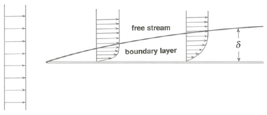
Probably the simplest example of a boundary layer is the one that develops on both surfaces of a stationary flat plate held parallel to a uniform free stream of fluid (Figure \(\PageIndex{1}\)). Just downstream of the leading edge of the plate the boundary layer is very thin, and the shearing necessitated by the transition from zero velocity to free-stream velocity is compressed into a thin zone of strong shear, so the shear stress at the surface of the plate is large (cf. Equation 1.3.6). Farther along the plate the boundary layer is thicker, because the motion of a greater thickness of fluid is retarded by the frictional influence of the plate, in the form of shear stresses exerted from layer to layer in the fluid; the shearing is therefore weaker, and the shear stress at the surface of the plate is smaller.
Boundary layers develop on objects of any shape immersed in a fluid moving relative to the object: flat plates as discussed above, airplane wings and other streamlined shapes, and blunt or bluff bodies like spheres or cylinders or sediment particles. Boundary layers also develop next to the external boundaries of a flow: the walls of pipes and ducts, the beds and bottoms of channels, the ocean bottom, and the land surface under the moving atmosphere. In every case the boundary layer has to start somewhere, as at the front surface or leading edge of a body immersed in the flow or at the upstream end of any solid boundary to the flow. And in every case it grows or expands downstream, until the flow passes by the body (the shearing motion engendered in the boundary layer is then degraded by viscous forces), or until it meets another boundary layer growing from some other surface, or until it reaches a free surface, or until it is prevented from further thickening by encountering a stably density-stratified layer of the medium—as is commonly the case in the atmosphere and in the deep ocean.
Laminar Boundary Layers and Turbulent Boundary Layers
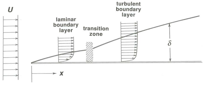
Flow in boundary layers may be either laminar or turbulent. A boundary layer that develops from the leading part of an object immersed in a free stream or at the head of a channel or conduit typically starts out as a laminar flow, but if it has a chance to grow for a long enough distance along the boundary it abruptly becomes turbulent. In the example of a flat-plate boundary layer (Figure \(\PageIndex{2}\)) we can define a Reynolds number \(\text{Re}_{\delta} = \rho U \delta/ \mu\) based on free-stream velocity \(U\) and boundary-layer thickness \(\delta\); just as in flow in a tube, discussed in a previous section, past a certain critical value of \(\text{Re}_{\delta}\) the laminar boundary layer is potentially unstable and may become turbulent. If there are no large turbulent eddies in the free stream, the laminar boundary layer may persist to very high Reynolds numbers; if the free stream is itself turbulent, or if the solid boundary surface is very rough, the boundary layer may become turbulent a very short distance downstream of the leading edge. Turbulence in the form of small spots develops at certain points in the laminar boundary layer, spreads rapidly, and soon engulfs the entire boundary layer.
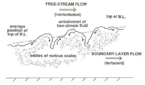
Once the boundary layer becomes turbulent it thickens faster, because fluid from the free stream is incorporated into the boundary layer at its outer edge in much the same way that clear air is incorporated into a turbulent plume of smoke (Figure \(\PageIndex{3}\)). That effect is in addition to, and as important as, the effect of incorporation of new fluid into the boundary layer just by local frictional action—which is the only way a laminar boundary layer can thicken. But the thickness of even a turbulent boundary layer grows fairly slowly relative to downstream distance; the angle between the average position of the outer edge of the boundary layer and the boundary itself is not very large, typically something like a few degrees.
Wakes
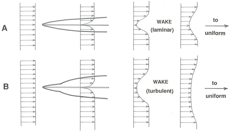
In situations where the flow passes all the way past some object of finite size surrounded by the flow, the boundary layer does not have a chance to develop beyond the vicinity of the body itself (Figure \(\PageIndex{4}\)). Downstream of the object the fluid that was retarded in the boundary layer is gradually reaccelerated by the free stream, until far downstream the velocity profile in the free stream no longer shows any evidence of the presence of the object upstream. The zone of retarded and often turbulent fluid downstream of the object is called the wake.
How Thick are Boundary Layers?
One usually thinks of a boundary layer as being thin compared to the scale of the body on which it develops. This is true at high Reynolds numbers, but it is not true at low Reynolds numbers. I will show you here, by a fairly simple line of reasoning, that the boundary-layer thickness varies inversely with the Reynolds number.
The thickness of the boundary layer is determined by the relative magnitude of two effects:
- The slowing of fluid farther and farther away from the solid surface by the action of fluid friction.
- The sweeping of that low-momentum fluid downstream and its replacement by fluid from upstream moving at the free-stream velocity.
The greater the second effect compared with the first, the thinner the boundary layer.
Think in terms of the downstream component of fluid momentum at some distance away from the solid boundary and at some distance downstream from the leading edge of the boundary layer. The rate of downstream transport of fluid momentum (written per unit volume of fluid) at the outer edge of the boundary layer is \(U(\rho U)\), where \(U\) is the free-stream velocity. The slowing of fluid by friction is a little trickier to deal with. Think back to Chapter 1, where I introduced the idea that the viscosity can be thought of as a cross-stream diffusion coefficient for downstream fluid momentum. In line with that idea, within the boundary layer the downstream fluid momentum is all the time diffusing toward the boundary. (Fluid dynamicists like to say that the boundary is a sink for momentum.) So the rate of cross-stream momentum diffusion is approximately equal to \(\mu (U / \delta)\), where \(U /\delta\) represents in a crude way the velocity gradient \(du / dy\) within the boundary layer.
The rate of thickening of the boundary layer is crudely represented by the ratio of downstream transport of momentum, on the one hand, to the rate of decrease of momentum at a place on account of the diffusion of momentum toward the boundary, both of these quantities having been derived in the last paragraph:
\(\frac{\text { cross-stream diffusion }}{\text { downstream transport }}=\frac{\mu U / \delta}{\rho U^{2}}\)
\(=\frac{\mu}{\rho U \delta}\)
\[=1 / \operatorname{Re} \delta \label{3.20} \]
Equation \ref{3.20} shows that the rate of boundary-layer thickening varies as the inverse of the Reynolds number based on boundary-layer thickness. This means that the boundary layer thickens more and more slowly in the downstream direction, so the cartoon of the flat-plate boundary layer in Figure \(\PageIndex{1}\), with the top of the boundary layer describing a curve that is concave toward the plate, is indeed qualitatively correct.
Equation \ref{3.20} also tells you that the larger the Reynolds number based on the mean flow and the size of the solid object on which the boundary layer is growing, the thinner the boundary layer is at a given point—because for given \(\delta\), \(\text{Re}_{\delta}\) is proportional to this Reynolds number. (For the flat plate, this Reynolds number is based on the distance from the leading edge; for the sphere, it is based most naturally on sphere diameter.) So the faster the free stream velocity and the larger the sphere (or the farther down the flat plate), and the smaller the viscosity, the thinner the boundary layer.
Keep in mind, as a final note, that all of the foregoing is for a laminar boundary layer—although the second part of the conclusion, that boundary-layer thickness is proportional to some Reynolds number defined on the size of the body, is qualitatively true for a turbulent boundary layer as well.
You might be wondering how thick boundary layers really are. This is something you can think about the next time you are sitting in a window seat over the wing, several miles above the Earth. How thick is the boundary layer at a distance of, say, one meter from the leading edge of the wing, when the plane is traveling at 500 miles an hour? There is an exact solution for the thickness of a laminar boundary layer as a function of the Reynolds number \(\text{Re}_{x}\) based on free- stream velocity and distance from the leading edge:
\[\delta=4.99 \mathrm{Re}_{x}^{-1 / 2} \label{3.21} \]
(The derivation of Equation \ref{3.21} is a little beyond this course; see Tritton, 1988, p. 127–129 if you are interested in pursuing it further.) Assuming an air temperature of \(-50^{\circ} \mathrm{C}\) and an altitude of \(35,000\) feet, the density of the air is about \(10^{-3} \mathrm{g} / \mathrm{cm}^{3}\) and the viscosity is something like \(1.5 \times 10^{-4}\) poise. Substituting the various values into Equation \ref{3.21}, we find that the boundary-layer thickness is a few hundredths of a millimeter. The boundary layer on the roof of your car at \(65 \mathrm{mph}\) is much thicker, by about an order of magnitude, because the air speed is so much slower.
Some Flows are "All Boundary Layer"
An example of the boundary layer growing to fill the entire flow is an open-channel flow that has just emerged from a sluice-like outlet at the bottom of a large reservoir of water (Figure \(\PageIndex{5}\)). Right at the inlet, the entire flow could be considered the “free stream”. As the flow passes down the channel, a boundary layer grows upward into the flow from the bottom. If the minor effect of friction with the atmosphere is neglected, no boundary layer develops at the upper surface of the flow. Eventually the growing boundary layer reaches the surface, and from that point downstream the river is all boundary layer!
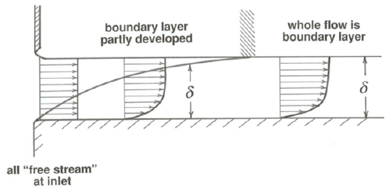
In a situation like this, boundary-layer development is typically complete in a downchannel distance equal to something like a few tens of flow depths. Upstream, in the zone of boundary-layer growth, the boundary layer is nonuniform, in that it is different at each section; downstream, in the zone of fully established flow, the boundary layer is uniform, in that it looks the same at every cross section.
Internal Boundary Layers
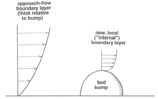
Finally, there can be boundary layers within boundary layers. Such boundary layers are called internal boundary layers. Suppose that a thick boundary layer is developing on a broad surface in contact with a flow, or a boundary layer has already grown to the full lateral extent of the flow, as in a river. Any solid object of restricted size immersed in that boundary layer, located either on the boundary, like some kind of irregularity or protuberance, or within the flow, like part of a submarine structure, causes the local development of another boundary layer (Figure \(\PageIndex{6}\)).
