10.7.2: Design aspects
- Page ID
- 16446
\( \newcommand{\vecs}[1]{\overset { \scriptstyle \rightharpoonup} {\mathbf{#1}} } \)
\( \newcommand{\vecd}[1]{\overset{-\!-\!\rightharpoonup}{\vphantom{a}\smash {#1}}} \)
\( \newcommand{\id}{\mathrm{id}}\) \( \newcommand{\Span}{\mathrm{span}}\)
( \newcommand{\kernel}{\mathrm{null}\,}\) \( \newcommand{\range}{\mathrm{range}\,}\)
\( \newcommand{\RealPart}{\mathrm{Re}}\) \( \newcommand{\ImaginaryPart}{\mathrm{Im}}\)
\( \newcommand{\Argument}{\mathrm{Arg}}\) \( \newcommand{\norm}[1]{\| #1 \|}\)
\( \newcommand{\inner}[2]{\langle #1, #2 \rangle}\)
\( \newcommand{\Span}{\mathrm{span}}\)
\( \newcommand{\id}{\mathrm{id}}\)
\( \newcommand{\Span}{\mathrm{span}}\)
\( \newcommand{\kernel}{\mathrm{null}\,}\)
\( \newcommand{\range}{\mathrm{range}\,}\)
\( \newcommand{\RealPart}{\mathrm{Re}}\)
\( \newcommand{\ImaginaryPart}{\mathrm{Im}}\)
\( \newcommand{\Argument}{\mathrm{Arg}}\)
\( \newcommand{\norm}[1]{\| #1 \|}\)
\( \newcommand{\inner}[2]{\langle #1, #2 \rangle}\)
\( \newcommand{\Span}{\mathrm{span}}\) \( \newcommand{\AA}{\unicode[.8,0]{x212B}}\)
\( \newcommand{\vectorA}[1]{\vec{#1}} % arrow\)
\( \newcommand{\vectorAt}[1]{\vec{\text{#1}}} % arrow\)
\( \newcommand{\vectorB}[1]{\overset { \scriptstyle \rightharpoonup} {\mathbf{#1}} } \)
\( \newcommand{\vectorC}[1]{\textbf{#1}} \)
\( \newcommand{\vectorD}[1]{\overrightarrow{#1}} \)
\( \newcommand{\vectorDt}[1]{\overrightarrow{\text{#1}}} \)
\( \newcommand{\vectE}[1]{\overset{-\!-\!\rightharpoonup}{\vphantom{a}\smash{\mathbf {#1}}}} \)
\( \newcommand{\vecs}[1]{\overset { \scriptstyle \rightharpoonup} {\mathbf{#1}} } \)
\( \newcommand{\vecd}[1]{\overset{-\!-\!\rightharpoonup}{\vphantom{a}\smash {#1}}} \)
\(\newcommand{\avec}{\mathbf a}\) \(\newcommand{\bvec}{\mathbf b}\) \(\newcommand{\cvec}{\mathbf c}\) \(\newcommand{\dvec}{\mathbf d}\) \(\newcommand{\dtil}{\widetilde{\mathbf d}}\) \(\newcommand{\evec}{\mathbf e}\) \(\newcommand{\fvec}{\mathbf f}\) \(\newcommand{\nvec}{\mathbf n}\) \(\newcommand{\pvec}{\mathbf p}\) \(\newcommand{\qvec}{\mathbf q}\) \(\newcommand{\svec}{\mathbf s}\) \(\newcommand{\tvec}{\mathbf t}\) \(\newcommand{\uvec}{\mathbf u}\) \(\newcommand{\vvec}{\mathbf v}\) \(\newcommand{\wvec}{\mathbf w}\) \(\newcommand{\xvec}{\mathbf x}\) \(\newcommand{\yvec}{\mathbf y}\) \(\newcommand{\zvec}{\mathbf z}\) \(\newcommand{\rvec}{\mathbf r}\) \(\newcommand{\mvec}{\mathbf m}\) \(\newcommand{\zerovec}{\mathbf 0}\) \(\newcommand{\onevec}{\mathbf 1}\) \(\newcommand{\real}{\mathbb R}\) \(\newcommand{\twovec}[2]{\left[\begin{array}{r}#1 \\ #2 \end{array}\right]}\) \(\newcommand{\ctwovec}[2]{\left[\begin{array}{c}#1 \\ #2 \end{array}\right]}\) \(\newcommand{\threevec}[3]{\left[\begin{array}{r}#1 \\ #2 \\ #3 \end{array}\right]}\) \(\newcommand{\cthreevec}[3]{\left[\begin{array}{c}#1 \\ #2 \\ #3 \end{array}\right]}\) \(\newcommand{\fourvec}[4]{\left[\begin{array}{r}#1 \\ #2 \\ #3 \\ #4 \end{array}\right]}\) \(\newcommand{\cfourvec}[4]{\left[\begin{array}{c}#1 \\ #2 \\ #3 \\ #4 \end{array}\right]}\) \(\newcommand{\fivevec}[5]{\left[\begin{array}{r}#1 \\ #2 \\ #3 \\ #4 \\ #5 \\ \end{array}\right]}\) \(\newcommand{\cfivevec}[5]{\left[\begin{array}{c}#1 \\ #2 \\ #3 \\ #4 \\ #5 \\ \end{array}\right]}\) \(\newcommand{\mattwo}[4]{\left[\begin{array}{rr}#1 \amp #2 \\ #3 \amp #4 \\ \end{array}\right]}\) \(\newcommand{\laspan}[1]{\text{Span}\{#1\}}\) \(\newcommand{\bcal}{\cal B}\) \(\newcommand{\ccal}{\cal C}\) \(\newcommand{\scal}{\cal S}\) \(\newcommand{\wcal}{\cal W}\) \(\newcommand{\ecal}{\cal E}\) \(\newcommand{\coords}[2]{\left\{#1\right\}_{#2}}\) \(\newcommand{\gray}[1]{\color{gray}{#1}}\) \(\newcommand{\lgray}[1]{\color{lightgray}{#1}}\) \(\newcommand{\rank}{\operatorname{rank}}\) \(\newcommand{\row}{\text{Row}}\) \(\newcommand{\col}{\text{Col}}\) \(\renewcommand{\row}{\text{Row}}\) \(\newcommand{\nul}{\text{Nul}}\) \(\newcommand{\var}{\text{Var}}\) \(\newcommand{\corr}{\text{corr}}\) \(\newcommand{\len}[1]{\left|#1\right|}\) \(\newcommand{\bbar}{\overline{\bvec}}\) \(\newcommand{\bhat}{\widehat{\bvec}}\) \(\newcommand{\bperp}{\bvec^\perp}\) \(\newcommand{\xhat}{\widehat{\xvec}}\) \(\newcommand{\vhat}{\widehat{\vvec}}\) \(\newcommand{\uhat}{\widehat{\uvec}}\) \(\newcommand{\what}{\widehat{\wvec}}\) \(\newcommand{\Sighat}{\widehat{\Sigma}}\) \(\newcommand{\lt}{<}\) \(\newcommand{\gt}{>}\) \(\newcommand{\amp}{&}\) \(\definecolor{fillinmathshade}{gray}{0.9}\)Origin of the sand
The required volumes of sand are in the order of magnitude up to several hundreds of millions m3 per project for large scale reclamation projects and up to 10 million m3 per project for smaller-scale nourishments.
The sand used for nourishments (borrow sand) can be obtained from land-based sources or from marine sources. The land-based sources may be river beds or dry sand deposits. The marine sources can be estuaries or the seabed. It is often attractive to try to combine excavation works with nourishment activities, to reduce the overall cost. (In Dutch: ‘werk met werk maken’).
When marine material is used it must be dredged at a sufficiently large distance from the shore to prevent extra erosion due to the presence of the borrow pits. Specifically, when material is dredged from the seabed, the question arises of whether it is better to dredge the material from small and deep borrow pits, or to dredge thin layers of the material from an extended borrow area. Dredging thin layers means disturbing the biologically active surface layer in a large area, whereas creating deep borrow pits enhances the risk of stagnant water of poor quality remaining in the deeper parts.
Although research into the effects of sand winning is being carried out, there is no clear conclusion yet. In the Netherlands, some sand is obtained by maintenance dredging in the access channels to Rotterdam and IJmuiden. The remaining amount of sand that is required is extracted by dredging thin layers at a distance of at least 20 km from the shore.
Although sand nourishment may offer significant benefits, it may also be a costly method if life spans are fairly short or if the long-term availability of adequate volumes of compatible borrow sand at nearby (economic) locations is problematic. For example, suitable material cannot easily be found at most Italian and Spanish sites along the Mediterranean.
A special application of an artificial nourishment project is when a sand-bypass system is used. A port built along a sandy coast or jetties to stabilise a mouth of a river flowing out into the sea, often cause updrift sedimentation and downdrift erosion of the coast. To avoid the erosion at the leeside, a sand-bypass system is a perfect tool. It artificially restores the blockage of the littoral drift by transporting sand from one side to the other. In Australia various examples are known of adequate and cost effective systems (e.g. Nerang River project and Tweed River project).
Quality requirements for the sand
When sand is supplied to a(n) (eroding) stretch of coast, the newly supplied sand will tend to form a crust or blanket over the existing coastal formations. The supplied sand will follow the physical laws that dominate the morphology in the same way as the existing sand. For this reason major changes in the slopes and other coastal features are to be expected when the grain size of the supplied sand differs from the original material. Usually, this is not acceptable, and one of the basic rules for beach nourishment is to use material that is relatively similar in grain size (and preferably grading) to the existing material (see also Sect. 10.7.3). However, in some cases the use of coarser material is preferable in order to diminish the losses.
Another point of concern is the silt content of the borrow material. The borrow material sometimes contains some (immobile) silt (2% silt is a quite normal percentage). During the dredging operation, silt is brought into the sea water via the overflow system of the dredge. This may have a negative impact on the marine environment. Besides, any fines still present in the material when fed to the coast may disrupt the ecological equilibrium of the coastal zone. Since the bottom material of a sandy shore is extremely mobile, specifically in the breaker zone, fines will have been washed out long ago, so that the water is relatively clear. It must therefore be ascertained that the beach nourishment material contains little or no fines. In the worst case, measures have to be taken to wash out the fines before placing the material on the beach.
Note that in Europe large areas have been allocated as Natura 2000 sites. Also dune and coastal areas are part of the Natura 2000 areas for which protection and prosperous developments are policy aims. If a nourishment project is foreseen in the vicinity of Natura 2000 areas, an assessment has to be made whether negative effects are to be expected.
Location of the nourishment

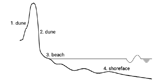
Sand nourishments can be placed at different locations in the coastal profile, namely (see Fig. 10.31):
- On the inner slope of the dunes;
- On the outer slope of the dunes;
- On the dry beach;
- On the shoreface.
In theory, as long as the nourishment location is within the active zone, waves will redistribute material over time from the nourishment location over the entire coastal profile in order to achieve an equilibrium profile again. Hence, nourishments of the shoreface and beach can be regarded as local perturbations of the profile, which will be flattened out by cross-shore sediment transport processes.

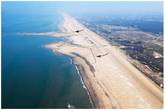
If a sand nourishment is carried out at locations 1 or 2, it is referred to as a dune nourishment. The use of sand from land-based sources is a reasonably cost-effective option in these cases. This is even more important if the use of marine sand would cause a salt intrusion problem in a vulnerable region. A nourishment at location 3 is called a beach nourishment and at location 4 a shoreface nourishment. Placing of the sand on the dry beach is sometimes complicated because it is necessary to cross the breaker zone with the dredging equipment (see Fig. 10.32). Since the breaker zone is an unfriendly place to work in, this is a cost item that cannot be neglected. Besides, beach recreation is hampered as a result of the pipelines that are needed to bring the sand to the beach and the noisy shovels needed to properly distribute the sand over the beach.

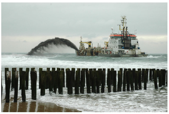
If compatible sand is available in nearby borrow areas, shoreface nourishments are more economical and recreation-friendly than beach nourishments because the sediment can be placed at the seaward edge of the surf zone where the navigational depth is sufficient for hopper dredgers. During calm wave conditions, material is dumped by shallow draft dredges (through doors in the bottom of the dredge or through rainbowing) at the shortest possible distance from the beach (see Fig. 10.33). Often shoreface nourishments are about half as expensive as beach nourishments.
The choice of the nourishment location further depends on the purpose of the nourishment. This is discussed in the next sections.


