
12.1.12: Diffraction by a Row of Atoms
- Page ID
- 18377

\( \newcommand{\vecs}[1]{\overset { \scriptstyle \rightharpoonup} {\mathbf{#1}} } \)
\( \newcommand{\vecd}[1]{\overset{-\!-\!\rightharpoonup}{\vphantom{a}\smash {#1}}} \)
\( \newcommand{\id}{\mathrm{id}}\) \( \newcommand{\Span}{\mathrm{span}}\)
( \newcommand{\kernel}{\mathrm{null}\,}\) \( \newcommand{\range}{\mathrm{range}\,}\)
\( \newcommand{\RealPart}{\mathrm{Re}}\) \( \newcommand{\ImaginaryPart}{\mathrm{Im}}\)
\( \newcommand{\Argument}{\mathrm{Arg}}\) \( \newcommand{\norm}[1]{\| #1 \|}\)
\( \newcommand{\inner}[2]{\langle #1, #2 \rangle}\)
\( \newcommand{\Span}{\mathrm{span}}\)
\( \newcommand{\id}{\mathrm{id}}\)
\( \newcommand{\Span}{\mathrm{span}}\)
\( \newcommand{\kernel}{\mathrm{null}\,}\)
\( \newcommand{\range}{\mathrm{range}\,}\)
\( \newcommand{\RealPart}{\mathrm{Re}}\)
\( \newcommand{\ImaginaryPart}{\mathrm{Im}}\)
\( \newcommand{\Argument}{\mathrm{Arg}}\)
\( \newcommand{\norm}[1]{\| #1 \|}\)
\( \newcommand{\inner}[2]{\langle #1, #2 \rangle}\)
\( \newcommand{\Span}{\mathrm{span}}\) \( \newcommand{\AA}{\unicode[.8,0]{x212B}}\)
\( \newcommand{\vectorA}[1]{\vec{#1}} % arrow\)
\( \newcommand{\vectorAt}[1]{\vec{\text{#1}}} % arrow\)
\( \newcommand{\vectorB}[1]{\overset { \scriptstyle \rightharpoonup} {\mathbf{#1}} } \)
\( \newcommand{\vectorC}[1]{\textbf{#1}} \)
\( \newcommand{\vectorD}[1]{\overrightarrow{#1}} \)
\( \newcommand{\vectorDt}[1]{\overrightarrow{\text{#1}}} \)
\( \newcommand{\vectE}[1]{\overset{-\!-\!\rightharpoonup}{\vphantom{a}\smash{\mathbf {#1}}}} \)
\( \newcommand{\vecs}[1]{\overset { \scriptstyle \rightharpoonup} {\mathbf{#1}} } \)
\( \newcommand{\vecd}[1]{\overset{-\!-\!\rightharpoonup}{\vphantom{a}\smash {#1}}} \)
\(\newcommand{\avec}{\mathbf a}\) \(\newcommand{\bvec}{\mathbf b}\) \(\newcommand{\cvec}{\mathbf c}\) \(\newcommand{\dvec}{\mathbf d}\) \(\newcommand{\dtil}{\widetilde{\mathbf d}}\) \(\newcommand{\evec}{\mathbf e}\) \(\newcommand{\fvec}{\mathbf f}\) \(\newcommand{\nvec}{\mathbf n}\) \(\newcommand{\pvec}{\mathbf p}\) \(\newcommand{\qvec}{\mathbf q}\) \(\newcommand{\svec}{\mathbf s}\) \(\newcommand{\tvec}{\mathbf t}\) \(\newcommand{\uvec}{\mathbf u}\) \(\newcommand{\vvec}{\mathbf v}\) \(\newcommand{\wvec}{\mathbf w}\) \(\newcommand{\xvec}{\mathbf x}\) \(\newcommand{\yvec}{\mathbf y}\) \(\newcommand{\zvec}{\mathbf z}\) \(\newcommand{\rvec}{\mathbf r}\) \(\newcommand{\mvec}{\mathbf m}\) \(\newcommand{\zerovec}{\mathbf 0}\) \(\newcommand{\onevec}{\mathbf 1}\) \(\newcommand{\real}{\mathbb R}\) \(\newcommand{\twovec}[2]{\left[\begin{array}{r}#1 \\ #2 \end{array}\right]}\) \(\newcommand{\ctwovec}[2]{\left[\begin{array}{c}#1 \\ #2 \end{array}\right]}\) \(\newcommand{\threevec}[3]{\left[\begin{array}{r}#1 \\ #2 \\ #3 \end{array}\right]}\) \(\newcommand{\cthreevec}[3]{\left[\begin{array}{c}#1 \\ #2 \\ #3 \end{array}\right]}\) \(\newcommand{\fourvec}[4]{\left[\begin{array}{r}#1 \\ #2 \\ #3 \\ #4 \end{array}\right]}\) \(\newcommand{\cfourvec}[4]{\left[\begin{array}{c}#1 \\ #2 \\ #3 \\ #4 \end{array}\right]}\) \(\newcommand{\fivevec}[5]{\left[\begin{array}{r}#1 \\ #2 \\ #3 \\ #4 \\ #5 \\ \end{array}\right]}\) \(\newcommand{\cfivevec}[5]{\left[\begin{array}{c}#1 \\ #2 \\ #3 \\ #4 \\ #5 \\ \end{array}\right]}\) \(\newcommand{\mattwo}[4]{\left[\begin{array}{rr}#1 \amp #2 \\ #3 \amp #4 \\ \end{array}\right]}\) \(\newcommand{\laspan}[1]{\text{Span}\{#1\}}\) \(\newcommand{\bcal}{\cal B}\) \(\newcommand{\ccal}{\cal C}\) \(\newcommand{\scal}{\cal S}\) \(\newcommand{\wcal}{\cal W}\) \(\newcommand{\ecal}{\cal E}\) \(\newcommand{\coords}[2]{\left\{#1\right\}_{#2}}\) \(\newcommand{\gray}[1]{\color{gray}{#1}}\) \(\newcommand{\lgray}[1]{\color{lightgray}{#1}}\) \(\newcommand{\rank}{\operatorname{rank}}\) \(\newcommand{\row}{\text{Row}}\) \(\newcommand{\col}{\text{Col}}\) \(\renewcommand{\row}{\text{Row}}\) \(\newcommand{\nul}{\text{Nul}}\) \(\newcommand{\var}{\text{Var}}\) \(\newcommand{\corr}{\text{corr}}\) \(\newcommand{\len}[1]{\left|#1\right|}\) \(\newcommand{\bbar}{\overline{\bvec}}\) \(\newcommand{\bhat}{\widehat{\bvec}}\) \(\newcommand{\bperp}{\bvec^\perp}\) \(\newcommand{\xhat}{\widehat{\xvec}}\) \(\newcommand{\vhat}{\widehat{\vvec}}\) \(\newcommand{\uhat}{\widehat{\uvec}}\) \(\newcommand{\what}{\widehat{\wvec}}\) \(\newcommand{\Sighat}{\widehat{\Sigma}}\) \(\newcommand{\lt}{<}\) \(\newcommand{\gt}{>}\) \(\newcommand{\amp}{&}\) \(\definecolor{fillinmathshade}{gray}{0.9}\)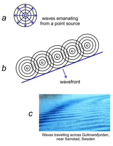
To discuss diffraction by a row of atoms, we can use the analogy of a group of campers standing on a lake dock. One camper throws a rock in the water, producing wave fronts that spread out in concentric circles before eventually dying out (Figure 12.11a).
Next, five campers on the dock all drop rocks into the water at different times, making many circular wavefronts. The wavefronts work with each other constructively in some directions and destructively in others. Most are out-of-phase and the waves disappear quickly.
But then they try an experiment. Five campers stand on the dock and all drop a rock into the water simultaneously. Each rock produces a circular wavefront. The five circular wavefronts are in phase and together create a straight wavefront that moves across the lake before eventually losing energy (Figure 12.11b). The rocks produce waves similar to a parallel set of wind-driven waves that might move across the ocean or across a lake (Figure 12.11c). If you are in a boat and see the waves coming toward you, you cannot tell that they were created by multiple in-phase point sources.
When a row of atoms scatters an X-ray beam, the atoms can produce a coherent wavefront similar to the one produced when rocks hit water simultaneously. Figure 12.11b could be showing a row of atoms each emitting X-ray waves with identical wavelengths. If all the atoms emit a wave simultaneously, the waves will create a straight wavefront moving away from the row. This is what happens when an incident X-ray beam strikes a row of atoms. The atoms scatter X-rays and create coherent wave fronts even if the incident wave hits the row of atoms at an angle. So, constructive interference produces a wavefront moving perpendicularly away from the row of atoms. And, as we will see shortly, wavefronts also travel in other directions.
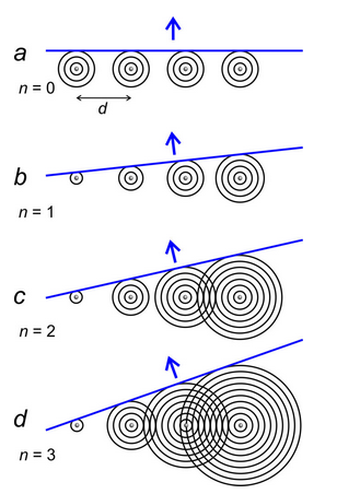
Figure 12.12a shows circular wavefronts emitted by atoms in a row. The difference in radius of adjacent wavefronts is the wavelength, λ. As described above, the waves, which have all traveled the same distance, combine to form straight wavefronts moving perpendicular to the row.
But because one cycle of a wave is the same as any other, it does not matter if waves have traveled different distances. If their peaks correspond, they are in phase. So, Figures 12.12 b, c, and d show that coherent wavefronts also move in other directions. In Figure 12.12b, waves emitted by adjacent atoms differ in travel distances by 1λ; in Figure 12.12c by 2λ; and in Figure 12.12d by 3λ.
Thus, we see that diffraction by a row of atoms in 2D produces wave fronts traveling in many directions. This is the same when 3D crystals diffract X-rays – diffracted rays go in many directions in 3D space.
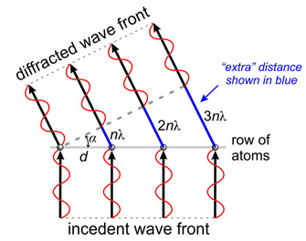
The geometry in Figure 12.12 yields a simple relationship between wavelength (λ), atomic spacing (d), and the angle of diffraction (α). In Figure 12.13, n is the number of wavelengths that each wave is behind (or ahead of) the one next to it. If the diffracted waves are in phase, application of trigonometry gives:
nλ = d sin α
n is called the order of diffraction. When n = 0, 0th order diffraction occurs and α must be 0. When n = 1, 1st-order diffraction occurs; when n = 2, 2nd-order diffraction occurs, and so on. As n increases, the angle between the diffracted wavefront and the row of atoms increases. The maximum value of nλ corresponds to sin α = 1 (when α = 90°), so nλ must always be less than d. Because n ≥ 1, λ must be less than or equal to d for diffraction to occur. These limits explain why atoms in crystals do not diffract visible light: the wavelengths of light are too long compared with the atomic spacings.
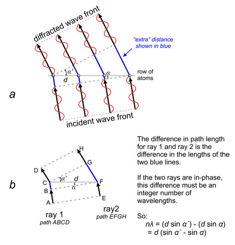
The preceding discussion assumed that an incident X-ray beam struck a row of atoms at 90°, but this is rarely the case. When the incident radiation strikes a row of atoms at another angle, coherent diffraction will still occur in any direction where X-rays are in phase (Figure 12.14a). To analyze this situation, we need only consider two rays (Figure 12.14b). They will be in phase if the difference in their path lengths, the difference between paths ABCD and EFGH, is an integral number of wavelengths (nλ). For the geometry shown in Figure 12.14b, we can easily verify that the rays will be in phase when:
d (sin α´ – sin α) = nλ
where d is the atomic spacing, αʹ and α are the angles of the diffracted and incident wave with the row of atoms, n is the order of diffraction, and λ is the wavelength. This is the general equation for diffraction by a row of atoms in 2D space. Von Laue was the first to derive this equation, and he derived similar equations for diffraction by three-dimensional structures. We call these the Laue equations.
W. L. Bragg developed a simpler mathematical treatment describing diffraction. His final equations are just as valid as von Laue’s, but the derivations avoided some unnecessary complexities. Although diffraction and reflection are two different processes, Bragg noted that diffracted X-rays behave as if they were reflected from planes within a crystal. To model this “reflection,” Bragg considered two parallel planes of atoms separated by distance dhkl (Figure 12.15).
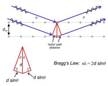
The blue lines in Figure 12.15 represent parallel monochromatic X-ray beams striking and reflecting from two (hkl) planes of atoms planes. The angle of incidence and the angle of reflection are both θ. The geometry in the inset photo shows how we can calculate the extra distance followed by the bottom ray. The path lengths of the two beams must vary by an integral number of wavelengths if diffraction is to occur. So, the extra path distance followed by the bottom ray must equal nλ, and:
nλ = 2dhkl sinθ
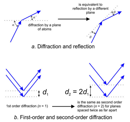
We call the equation above Bragg’s Law. Bragg demonstrated that we need not consider situations in which incident and diffraction angles are different (Figure 12.16a). Because we can always describe diffraction using reflection geometry, although diffraction and reflection are different phenomena. The angle of “reflection” θ is related to the incident angle (α) and the diffraction angle (αʹ) by
θ = (α – αʹ)/2
Examination of Bragg’s Law reveals that if we double the value of n (the order of diffraction) and we double the value of dhkl, θ will not change (diffraction will occur at the same angle.) So, 1st-order diffraction by planes with spacing dhkl occurs at the same angle as 2nd-order diffraction by a set of planes spaced twice as far apart. Figure 12.16b shows this relationship. Because we have no way to know diffraction order (n) when conducting routine X-ray studies, assuming 1st-order is simplest. In other applications of Bragg’s Law, the order of diffraction is important.
For more about Laue patterns, Bragg’s Law and diffractograms, watch these videos:
Video 12-1: Braggs’ Law and diffractograms (6 minutes)
Video 12-2: Laue Patterns and Bragg’s Law (10 minutes)