Photo Attribution: Emerald, Muzo Mine, Vasquez-Yacopí Mining District, Boyacá Department
File:Béryl var. émeraude sur gangue (Muzo Mine Boyaca – Colombie) 2.jpg. (2018, August 10). Wikimedia Commons, the free media repository. Retrieved 17:51, February 11, 2019 from
commons.wikimedia.org/w/index.php?title=File:B%C3%A9ryl_var._%C3%A9meraude_sur_gangue_(Muzo_Mine_Boyaca_-_Colombie)_2.jpg&oldid=314327347.
2.3: Light and Optics
- Page ID
- 11104
\( \newcommand{\vecs}[1]{\overset { \scriptstyle \rightharpoonup} {\mathbf{#1}} } \)
\( \newcommand{\vecd}[1]{\overset{-\!-\!\rightharpoonup}{\vphantom{a}\smash {#1}}} \)
\( \newcommand{\id}{\mathrm{id}}\) \( \newcommand{\Span}{\mathrm{span}}\)
( \newcommand{\kernel}{\mathrm{null}\,}\) \( \newcommand{\range}{\mathrm{range}\,}\)
\( \newcommand{\RealPart}{\mathrm{Re}}\) \( \newcommand{\ImaginaryPart}{\mathrm{Im}}\)
\( \newcommand{\Argument}{\mathrm{Arg}}\) \( \newcommand{\norm}[1]{\| #1 \|}\)
\( \newcommand{\inner}[2]{\langle #1, #2 \rangle}\)
\( \newcommand{\Span}{\mathrm{span}}\)
\( \newcommand{\id}{\mathrm{id}}\)
\( \newcommand{\Span}{\mathrm{span}}\)
\( \newcommand{\kernel}{\mathrm{null}\,}\)
\( \newcommand{\range}{\mathrm{range}\,}\)
\( \newcommand{\RealPart}{\mathrm{Re}}\)
\( \newcommand{\ImaginaryPart}{\mathrm{Im}}\)
\( \newcommand{\Argument}{\mathrm{Arg}}\)
\( \newcommand{\norm}[1]{\| #1 \|}\)
\( \newcommand{\inner}[2]{\langle #1, #2 \rangle}\)
\( \newcommand{\Span}{\mathrm{span}}\) \( \newcommand{\AA}{\unicode[.8,0]{x212B}}\)
\( \newcommand{\vectorA}[1]{\vec{#1}} % arrow\)
\( \newcommand{\vectorAt}[1]{\vec{\text{#1}}} % arrow\)
\( \newcommand{\vectorB}[1]{\overset { \scriptstyle \rightharpoonup} {\mathbf{#1}} } \)
\( \newcommand{\vectorC}[1]{\textbf{#1}} \)
\( \newcommand{\vectorD}[1]{\overrightarrow{#1}} \)
\( \newcommand{\vectorDt}[1]{\overrightarrow{\text{#1}}} \)
\( \newcommand{\vectE}[1]{\overset{-\!-\!\rightharpoonup}{\vphantom{a}\smash{\mathbf {#1}}}} \)
\( \newcommand{\vecs}[1]{\overset { \scriptstyle \rightharpoonup} {\mathbf{#1}} } \)
\( \newcommand{\vecd}[1]{\overset{-\!-\!\rightharpoonup}{\vphantom{a}\smash {#1}}} \)
\(\newcommand{\avec}{\mathbf a}\) \(\newcommand{\bvec}{\mathbf b}\) \(\newcommand{\cvec}{\mathbf c}\) \(\newcommand{\dvec}{\mathbf d}\) \(\newcommand{\dtil}{\widetilde{\mathbf d}}\) \(\newcommand{\evec}{\mathbf e}\) \(\newcommand{\fvec}{\mathbf f}\) \(\newcommand{\nvec}{\mathbf n}\) \(\newcommand{\pvec}{\mathbf p}\) \(\newcommand{\qvec}{\mathbf q}\) \(\newcommand{\svec}{\mathbf s}\) \(\newcommand{\tvec}{\mathbf t}\) \(\newcommand{\uvec}{\mathbf u}\) \(\newcommand{\vvec}{\mathbf v}\) \(\newcommand{\wvec}{\mathbf w}\) \(\newcommand{\xvec}{\mathbf x}\) \(\newcommand{\yvec}{\mathbf y}\) \(\newcommand{\zvec}{\mathbf z}\) \(\newcommand{\rvec}{\mathbf r}\) \(\newcommand{\mvec}{\mathbf m}\) \(\newcommand{\zerovec}{\mathbf 0}\) \(\newcommand{\onevec}{\mathbf 1}\) \(\newcommand{\real}{\mathbb R}\) \(\newcommand{\twovec}[2]{\left[\begin{array}{r}#1 \\ #2 \end{array}\right]}\) \(\newcommand{\ctwovec}[2]{\left[\begin{array}{c}#1 \\ #2 \end{array}\right]}\) \(\newcommand{\threevec}[3]{\left[\begin{array}{r}#1 \\ #2 \\ #3 \end{array}\right]}\) \(\newcommand{\cthreevec}[3]{\left[\begin{array}{c}#1 \\ #2 \\ #3 \end{array}\right]}\) \(\newcommand{\fourvec}[4]{\left[\begin{array}{r}#1 \\ #2 \\ #3 \\ #4 \end{array}\right]}\) \(\newcommand{\cfourvec}[4]{\left[\begin{array}{c}#1 \\ #2 \\ #3 \\ #4 \end{array}\right]}\) \(\newcommand{\fivevec}[5]{\left[\begin{array}{r}#1 \\ #2 \\ #3 \\ #4 \\ #5 \\ \end{array}\right]}\) \(\newcommand{\cfivevec}[5]{\left[\begin{array}{c}#1 \\ #2 \\ #3 \\ #4 \\ #5 \\ \end{array}\right]}\) \(\newcommand{\mattwo}[4]{\left[\begin{array}{rr}#1 \amp #2 \\ #3 \amp #4 \\ \end{array}\right]}\) \(\newcommand{\laspan}[1]{\text{Span}\{#1\}}\) \(\newcommand{\bcal}{\cal B}\) \(\newcommand{\ccal}{\cal C}\) \(\newcommand{\scal}{\cal S}\) \(\newcommand{\wcal}{\cal W}\) \(\newcommand{\ecal}{\cal E}\) \(\newcommand{\coords}[2]{\left\{#1\right\}_{#2}}\) \(\newcommand{\gray}[1]{\color{gray}{#1}}\) \(\newcommand{\lgray}[1]{\color{lightgray}{#1}}\) \(\newcommand{\rank}{\operatorname{rank}}\) \(\newcommand{\row}{\text{Row}}\) \(\newcommand{\col}{\text{Col}}\) \(\renewcommand{\row}{\text{Row}}\) \(\newcommand{\nul}{\text{Nul}}\) \(\newcommand{\var}{\text{Var}}\) \(\newcommand{\corr}{\text{corr}}\) \(\newcommand{\len}[1]{\left|#1\right|}\) \(\newcommand{\bbar}{\overline{\bvec}}\) \(\newcommand{\bhat}{\widehat{\bvec}}\) \(\newcommand{\bperp}{\bvec^\perp}\) \(\newcommand{\xhat}{\widehat{\xvec}}\) \(\newcommand{\vhat}{\widehat{\vvec}}\) \(\newcommand{\uhat}{\widehat{\uvec}}\) \(\newcommand{\what}{\widehat{\wvec}}\) \(\newcommand{\Sighat}{\widehat{\Sigma}}\) \(\newcommand{\lt}{<}\) \(\newcommand{\gt}{>}\) \(\newcommand{\amp}{&}\) \(\definecolor{fillinmathshade}{gray}{0.9}\)Introduction
You may be well aware of the importance of visible light for making observations in the geosciences. For example, the color of minerals and rocks can help us identify them (although it is not always the best identifier!). Color is determined by the relative absorbance or reflection of different wavelengths of visible light.
For example, a gem-quality emerald is a deep green color. This is because it is reflecting the green wavelengths of light to our eyes, and is absorbing the other visible wavelengths of light. Emerald is the mineral beryl, but it is trace Cr3+ in the mineral structure that causes the green color.
Figure 2.3.1 Emerald from Muzo Mine, Columbia
Visible light represents a small range of the electromagnetic spectrum. Even though no human can see beyond the visible range, we can still use technology to “see” the electromagnetic spectrum beyond anyone’s reach.
The electromagnetic energy we cannot see (but can detect with instrumentation) can be used to study the chemical composition of materials, can detect the vibrations of molecules and minerals, and can see the structure of solid materials, among other things.
This chapter provides a practical basis for applying knowledge of electromagnetic energy to optical microscopy.
Learning Objectives
Students should be able to:
- Describe the categories of electromagnetic energy within the electromagnetic spectrum, and be able to place these categories relative to each other in wavelength and energy.
- Describe the wavelengths of visible light and name a color for a given wavelength range.
- Describe the ways in which electromagnetic energy can behave when it interacts with an object.
- Define characteristics of light, including the speed of light, wave front, and light ray.
- Define refractive index.
- Differentiate between the electric and magnetic components of light.
- Use the electric (E) vector of light to describe the behavior of plane polarized light.
Prior Knowledge and Skills
None
The Electromagnetic Spectrum
The video below gives an overview of the electromagnetic spectrum:
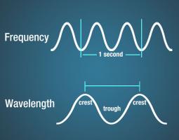
Electromagnetic waves have crests and troughs similar to (but not identical in behavior to) those of ocean waves. The distance between crests is the wavelength.
The figure below shows the wavelength (meters) and energy (Hz) ranges for different types of electromagnetic energy:

After watching the video and examining the figure above, answer these questions:
Question \(\PageIndex{1}\)
Question \(\PageIndex{2}\)
Question \(\PageIndex{3}\)
Visible Light

The visible light region is divided into color regions (Figure 2.3.4). We will use colors (and color changes due to different microscopy techniques) to help identify minerals under thin section.
Question \(\PageIndex{4}\)
Question \(\PageIndex{5}\)
Behavior of Light
Light waves across the electromagnetic spectrum behave in similar ways. When a light wave encounters an object, it is either transmitted, reflected, absorbed, refracted, polarized, diffracted, or scattered depending on the composition of the object and the wavelength of the light.
Absorption, Transmission, and Reflection
This video reviews the concepts of absorption, transmission, and reflection of light:
Diffraction, Scattering, and Refraction
Diffraction is the bending and spreading of waves around an obstacle. It is most pronounced when a light wave strikes an object with a size comparable to its own wavelength. In the case of visible light, the separation of wavelengths through diffraction results in a rainbow. The figure below shows the grooves on a CD diffracting visible light and producing iridescent colors.

Scattering occurs when light bounces off an object in a variety of directions. The amount of scattering that takes place depends on the wavelength of the light and the size and structure of the object.
The sky appears blue because of this scattering behavior. Light at shorter wavelengths—blue and violet—is scattered by nitrogen and oxygen as it passes through the atmosphere. Longer wavelengths of light—red and yellow—transmit through the atmosphere. This scattering of light at shorter wavelengths illuminates the skies with light from the blue and violet end of the visible spectrum. Even though violet is scattered more than blue, the sky looks blue to us because our eyes are more sensitive to blue light.
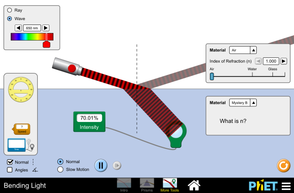
Refraction is when light waves change direction as they pass from one medium to another. Light travels slower in air than in a vacuum, and even slower in water. As light travels into a different medium, the change in speed bends the light. Different wavelengths of light are slowed at different rates, which causes them to bend at different angles. For example, when the full spectrum of visible light travels through the glass of a prism, or through a raindrop, the wavelengths are separated into the colors of the rainbow.
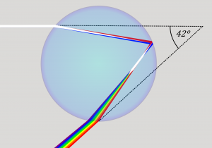
We will discuss refraction in more detail and introduce polarization of light in the sections below. These concepts are especially important for understanding techniques in optical mineralogy and petrology.
Guided Inquiry Question \(\PageIndex{6}\)
Properties of Light
The speed of light (electromagnetic energy) in a vacuum is a constant value: c = 3.00 x 10⁸ m/s. However, we will see below that electromagnetic energy slows down when it travels through matter, including minerals.
Knowing the propagation direction or direction of travel is important if we wish to understand how light moves through the microscope and our samples. The diagram below shows three views of an electromagnetic wave. In each view , a light ray pointing parallel to the direction of propagation and the wavefront perpendicular to the propagation direction are shown.

Guided Inquiry Question \(\PageIndex{7}\)
Electromagnetic waves contain both electric and magnetic fields that change or oscillate. The electric field vector E is always perpendicular to the magnetic field vector B. Both E and B are perpendicular to the propagation direction of the wave. We will learn more about the electric field vector E in the section on polarization of light.

Refractive Index
Electromagnetic energy travels at the speed of light, c, in a vacuum. However, when electromagnetic waves travel through matter, they slow down. The speed at which they travel through a material is specific to the density and composition of the material.
The refractive index of a material characterizes the relationship between the speed of light in a vacuum and the speed of light in that material.
The refractive index of a material is defined as:
where n is the refractive index, c is the speed of light in a vacuum, and v is the observed speed of light in the material. Since the speed of light in matter is always less than c, the index of refraction is always greater than or equal to one.
This table lists some examples of refractive indices of different materials:
| Refractive Indices of Materials | |
| Material | n |
| Air (0 Celsius, 1 atm) | 1.000293 |
| Water, fresh | 1.333 |
| Glass, crown | 1.52 |
| Quartz | 1.544 |
| Zircon | 1.923 |
| Diamond | 2.419 |
Guided Inquiry Question \(\PageIndex{8}\)
The amount that a light ray changes its direction depends both on the incident angle and the amount that the speed changes. For a ray at a given incident angle, a large change in speed causes a large change in direction and thus a large change in angle. The exact mathematical relationship is the law of refraction, or Snell’s law, after the Dutch mathematician Willebrord Snell (1591–1626), who discovered it in 1621. The law of refraction is stated in equation form as:
Here n1 and n2 are the indices of refraction for media 1 and 2, and θ1 and θ2 are the angles between the rays and the perpendicular in media 1 and 2. The incoming ray is called the incident ray, the outgoing ray is called the refracted ray, and the associated angles are the incident angle and the refracted angle, respectively.

Figure 2.3.9 shows how a ray of light changes direction when it passes from one medium to another. The angles are measured relative to a perpendicular to the surface at the point where the light ray crosses it. (Some of the incident light will be reflected from the surface, but for now we will concentrate on the light that is transmitted.) The change in direction of the light ray depends on how the speed of light changes. The change in the speed of light is related to the indices of refraction of the media involved. In the situations shown in Figure 2.3.9 medium 2 has a greater index of refraction than medium 1. This means that the speed of light is less in medium 2 than in medium 1.
Note that as shown in Figure 2.3.9(a), the direction of the ray moves closer to the perpendicular when it slows down. Conversely, as shown in Figure 2.3.9(b), the direction of the ray moves away from the perpendicular when it speeds up. The path is exactly reversible.
In both cases, you can imagine what happens by thinking about pushing a lawn mower from a footpath onto grass, and vice versa. Going from the footpath to grass, the front wheels are slowed and pulled to the side as shown. This is the same change in direction as for light when it goes from a fast medium to a slow one. When going from the grass to the footpath, the front wheels can move faster and the mower changes direction as shown. This, too, is the same change in direction as for light going from slow to fast.
Question \(\PageIndex{9}\)
Question \(\PageIndex{10}\)
Polarized Light
Polaroid sunglasses are familiar to most of us. They have a special ability to cut the glare of light reflected from water or glass. Polaroids have this ability because of a wave characteristic of light called polarization. What is polarization? How is it produced? What are some of its uses? The answers to these questions are related to the wave character of light.
Watch the first 6 minutes of the video below to see a practical overview of plane polarized light, using crossed polarizers, and how a third polarizer (which is how many minerals act) can be used to increase light output from crossed polarizers.
The Sun and many other light sources produce waves in which E (and B, though it is not shown) are not preferentially oriented – they exist in every direction perpendicular to the direction of propagation (see Figure 2.3.11). Such light is said to be unpolarized because it is composed of many waves with all possible directions of polarization.
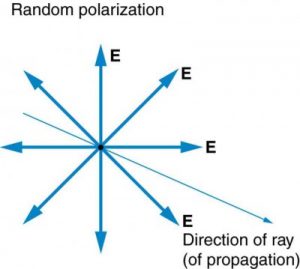
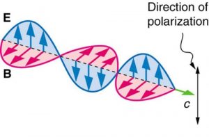
In contrast, light that is plane polarized (also called linearly polarized) has E oriented in one specific direction in space (Figure 2.3.12). The polarization direction is defined by the orientation of E (as opposed to B).
Polarizers are composed of long molecules aligned in one direction. Thinking of the molecules as many slits, analogous to those for the oscillating ropes, we can understand why only light with a specific polarization can get through. The axis of a polarizing filter is the direction along which the filter passes the electric field of an EM wave (see Figure 2.3.13).
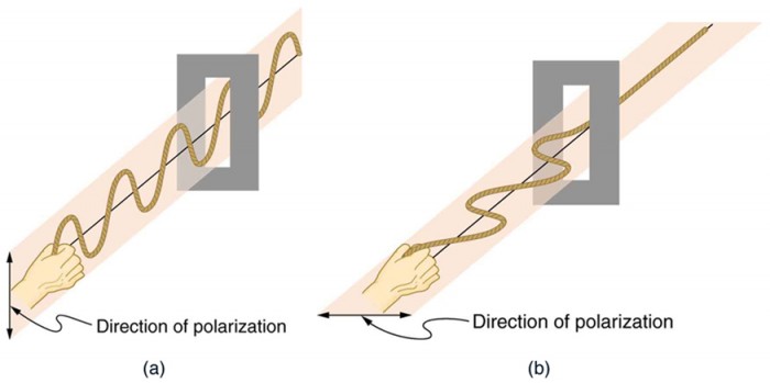
To examine this further, consider the transverse waves in the ropes shown in Figure2.3.13. The oscillations in one rope are in a vertical plane and are said to be vertically polarized. Those in the other rope are in a horizontal plane and are horizontally polarized. If a vertical slit is placed on the first rope, the waves pass through. However, a vertical slit blocks the horizontally polarized waves. For EM waves, the direction of the electric field vector E is analogous to the disturbances on the ropes (Figure 2.3.14).

ATOMIC EXPLANATION OF POLARIZING FILTERS
Polarizing filters have a polarization axis that acts as a slit. This slit passes electromagnetic waves (often visible light) that have an electric field parallel to the axis. This is accomplished with long molecules aligned perpendicular to the axis as shown in Figure 2.3.15.

Figure 2.3.16 illustrates how the component of the electric field parallel to the long molecules is absorbed. An electromagnetic wave is composed of oscillating electric and magnetic fields. The electric field is strong compared with the magnetic field and is more effective in exerting force on charges in the molecules. The most affected charged particles are the electrons in the molecules, since electron masses are small. If the electron is forced to oscillate, it can absorb energy from the EM wave. This reduces the fields in the wave and, hence, reduces its intensity. In long molecules, electrons can more easily oscillate parallel to the molecule than in the perpendicular direction. The electrons are bound to the molecule and are more restricted in their movement perpendicular to the molecule. Thus, the electrons can absorb EM waves that have a component of their electric field parallel to the molecule. The electrons are much less responsive to electric fields perpendicular to the molecule and will allow those fields to pass. Thus the axis of the polarizing filter is perpendicular to the length of the molecule.
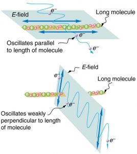
Figure 2.3.17 shows the effect of two polarizing filters on originally unpolarized light. The first filter polarizes the light along its axis. When the axes of the first and second filters are aligned (parallel), then all of the polarized light passed by the first filter is also passed by the second. If the second polarizing filter is rotated, only the component of the light parallel to the second filter’s axis is passed. When the axes are perpendicular, no light is passed by the second.
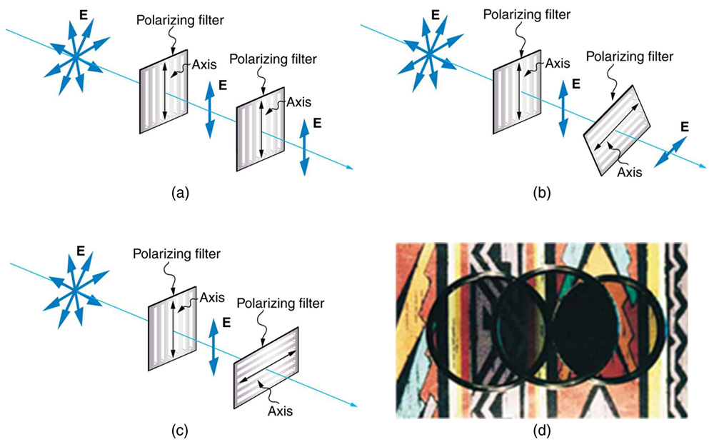
Only the component of the EM wave parallel to the axis of a filter is passed. Let us call the angle between the direction of polarization and the axis of a filter θ. If the electric field has an amplitude E, then the transmitted part of the wave has an amplitude E cos θ (see Figure 2.3.18). Since the intensity of a wave is proportional to its amplitude squared, the intensity I of the transmitted wave is related to the incident wave by I = I0 cos2 θ, where I0 is the intensity of the polarized wave before passing through the filter.

Liquid Crystal DISPLAYS and Optically Active Materials
While you are undoubtedly aware of liquid crystal displays (LCDs) found in watches, calculators, computer screens, cellphones, flat screen televisions, and other myriad places, you may not be aware that they are based on polarization. Liquid crystals are so named because their molecules can be aligned even though they are in a liquid. Liquid crystals have the property that they can rotate the polarization of light passing through them by 90 degrees. Furthermore, this property can be turned off by the application of a voltage, as illustrated in Figure 2.3.19. It is possible to manipulate this characteristic quickly and in small well-defined regions to create the contrast patterns we see in so many LCD devices.

In flat screen LCD televisions, there is a large light at the back of the TV. The light travels to the front screen through millions of tiny units called pixels (picture elements). One of these is shown in Figure 2.3.19 (a) and (b). Each unit has three cells, with red, blue, or green filters, each controlled independently. When the voltage across a liquid crystal is switched off, the liquid crystal passes the light through the particular filter. One can vary the picture contrast by varying the strength of the voltage applied to the liquid crystal.
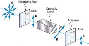
Many crystals and solutions rotate the plane of polarization of light passing through them. Such substances are said to be optically active. Examples include sugar water, insulin, and collagen (see Figure 2.3.20). In addition to depending on the type of substance, the amount and direction of rotation depends on a number of factors. Among these is the concentration of the substance, the distance the light travels through it, and the wavelength of light. Optical activity is due to the asymmetric shape of molecules in the substance, such as being helical. Measurements of the rotation of polarized light passing through substances can thus be used to measure concentrations, a standard technique for sugars. It can also give information on the shapes of molecules, such as proteins, and factors that affect their shapes, such as temperature and pH.

Glass and plastic become optically active when stressed; the greater the stress, the greater the effect. Optical stress analysis on complicated shapes can be performed by making plastic models of them and observing them through crossed filters, as seen in Figure 2.3.21. It is apparent that the effect depends on wavelength as well as stress. The wavelength dependence is sometimes also used for artistic purposes.
Birefrigence
Another interesting phenomenon associated with polarized light is the ability of some minerals and other crystals to split an unpolarized beam of light into two polarized beams (Figure 2.3.22). Such crystals are said to be birefringent.
Each of the separated rays has a specific polarization. One behaves normally and is called the ordinary ray (o or ω), whereas the other does not obey Snell’s law and is called the extraordinary ray (e or ε). Birefringent crystals can be used to produce polarized beams from unpolarized light. Some birefringent materials preferentially absorb one of the polarizations. These materials are called dichroic and can produce polarization by this preferential absorption. This is fundamentally how polarizing filters and other polarizers work. We will use the property of birefringence to help us identify and distinguish minerals in thin section!

Key Terms
- Wavelength
- Frequency
- Visible, Infrared, Ultraviolet light
- Transmission
- Reflection
- Absorption
- Diffraction
- Scattering
- Refraction
- Polarization
- Speed of Light
- Wave front
- Ray
- Electric field vector
- Magnetic field vector
- Refractive Index
- Snell’s Law
- Transverse wave
- Unpolarized
- Plane (linear) polarization
- Birefringence
- Ordinary Ray
- Extraordinary Ray
References
Bozeman Science (Jun 11, 2015) Light Absorption, Reflection, and Transmission. https://youtu.be/DOsro2kGjGc
Lumen Learning. Physics. CC-BY. https://courses.lumenlearning.com/physics/
National Aeronautics and Space Administration, Science Mission Directorate. (2010). Anatomy of an Electromagnetic Wave. Retrieved March 9, 2019, from NASA Science website: http://science.nasa.gov/ems/02_anatomy
National Aeronautics and Space Administration, Science Mission Directorate. (2010). Introduction to the Electromagnetic Spectrum. Retrieved March 9, 2019, from NASA Science website: http://science.nasa.gov/ems/01_intro
National Aeronautics and Space Administration, Science Mission Directorate. (2010). Wave Behaviors. Retrieved March 9, 2019 from NASA Science website: http://science.nasa.gov/ems/03_behaviors
OpenStax, College Physics. Creative Commons Attribution License v4.0. https://openstax.org/details/books/college-physics.
OpenStax, University Physics Volume 3. Creative Commons Attribution License 4.0 license. https://openstax.org/books/university-physics-volume-3/pages/1-1-the-propagation-of-light
PhET Interactive Simulations, University of Colorado Boulder. Bending Light. CC_BY. https://phet.colorado.edu/en/simulation/bending-light
Attributions
Return to Table of Contents


