
13.2: Tools at a geologist's disposal
- Page ID
- 22669

\( \newcommand{\vecs}[1]{\overset { \scriptstyle \rightharpoonup} {\mathbf{#1}} } \)
\( \newcommand{\vecd}[1]{\overset{-\!-\!\rightharpoonup}{\vphantom{a}\smash {#1}}} \)
\( \newcommand{\id}{\mathrm{id}}\) \( \newcommand{\Span}{\mathrm{span}}\)
( \newcommand{\kernel}{\mathrm{null}\,}\) \( \newcommand{\range}{\mathrm{range}\,}\)
\( \newcommand{\RealPart}{\mathrm{Re}}\) \( \newcommand{\ImaginaryPart}{\mathrm{Im}}\)
\( \newcommand{\Argument}{\mathrm{Arg}}\) \( \newcommand{\norm}[1]{\| #1 \|}\)
\( \newcommand{\inner}[2]{\langle #1, #2 \rangle}\)
\( \newcommand{\Span}{\mathrm{span}}\)
\( \newcommand{\id}{\mathrm{id}}\)
\( \newcommand{\Span}{\mathrm{span}}\)
\( \newcommand{\kernel}{\mathrm{null}\,}\)
\( \newcommand{\range}{\mathrm{range}\,}\)
\( \newcommand{\RealPart}{\mathrm{Re}}\)
\( \newcommand{\ImaginaryPart}{\mathrm{Im}}\)
\( \newcommand{\Argument}{\mathrm{Arg}}\)
\( \newcommand{\norm}[1]{\| #1 \|}\)
\( \newcommand{\inner}[2]{\langle #1, #2 \rangle}\)
\( \newcommand{\Span}{\mathrm{span}}\) \( \newcommand{\AA}{\unicode[.8,0]{x212B}}\)
\( \newcommand{\vectorA}[1]{\vec{#1}} % arrow\)
\( \newcommand{\vectorAt}[1]{\vec{\text{#1}}} % arrow\)
\( \newcommand{\vectorB}[1]{\overset { \scriptstyle \rightharpoonup} {\mathbf{#1}} } \)
\( \newcommand{\vectorC}[1]{\textbf{#1}} \)
\( \newcommand{\vectorD}[1]{\overrightarrow{#1}} \)
\( \newcommand{\vectorDt}[1]{\overrightarrow{\text{#1}}} \)
\( \newcommand{\vectE}[1]{\overset{-\!-\!\rightharpoonup}{\vphantom{a}\smash{\mathbf {#1}}}} \)
\( \newcommand{\vecs}[1]{\overset { \scriptstyle \rightharpoonup} {\mathbf{#1}} } \)
\( \newcommand{\vecd}[1]{\overset{-\!-\!\rightharpoonup}{\vphantom{a}\smash {#1}}} \)
Sedimentary rocks, whether terrigenous, carbonate, chemical, or volcaniclastic, contain a wealth of information that relate how they formed at or close to Earth’s surface, and the various physical and chemical processes that affected them as they were buried. This article deals with the first part of the journey:
1. How sediment moves across a substrate,
2. The language of bedforms,
3. The hydrodynamic significance of bedforms, and
4. An atlas of common sedimentary structures
TRANSPORT OF SEDIMENT; BEDLOAD AND SUSPENSION LOAD

Movement of sediment creates beds, structures within beds (e.g., laminations, crossbedding), and entire depositional systems like deltas and submarine fans. The processes by which sediment moves determine what the deposit will look like: a train of ripples, turbidites, a layer of mud, or Martian sand dunes.
In this section we will examine four of these processes:
- The case where a fluid, (water, air) interacts with a bed of loose sand – i.e., bedload transport;
- Where sediment accumulates from a suspension of water and fine particles, and;
- Movement of sediment by surface waves;
- Bedforms in relation to fluid flow – the flow regime.
Bedload
As the name suggests, this element of sediment movement consists of loose, granular particles at the sediment-water interface (such as a stream bed or tidal flat): in other words, at the top of a bed. Air or water that moves across the bed will begin to move grains if the flow velocity is great enough to overcome the force of gravity and any resistance at grain contacts. This is the threshold velocity.
The bedload contains two main components:
- the traction load, or traction “carpet,” and
- the saltation load.

The various components of force involved in initiation of grain movement are shown here. Fluid flowing over a sediment bed produces shear stresses that can be resolved into a component of drag (parallel to the bed) and a lift component (perpendicular to the bed). At the threshold velocity when the resultant fluid force on grains becomes greater than gravity, grains begin to roll, slide and jostle along the bed like a moving carpet – the traction carpet.
The short video is of wind ripples where sand moves in a traction carpet (viewed best in full screen).
https://opengeology.org/historicalge...y/pss/#Bedload
As flow velocities increase, so too will the lift component of fluid forces and grains may temporarily leave the traction carpet, bouncing along with the flow; this process is called saltation. The saltation load is included in bedload because grain excursions into the fluid do not last long. Saltating grains tend to travel much farther in air than water because the contrast in density between the grain and the fluid is much greater. Stand on any sandy beach on a blustery day and you will witness first-hand the effects of grain saltation. Saltation produces many collisions, and not just against your bare legs. Saltation collisions also result in grain abrasion.
The short video shows a saltation load across a windy, black sand beach (sand consists of magnetite, ilmenite and pyroxenes). Saltation also tends to winnow the lighter pyroxenes, separating them from the denser iron oxides.
https://opengeology.org/historicalge...y/pss/#Bedload
The ease with which grains move also depends on their density and shape. Quartz grains will move more easily than heavier minerals of the same size. Because they are shaped like little hang-gliders, platy grains like micas, even though they are denser than quartz, will tend to respond hydraulically as lighter particles.

The Hjulström curve plots two domains: the erosion curve shows the critical flow velocity required to move a sedimentary particle across a bed, and the deposition curve the flow velocity at which the particle will be deposited (cease to move). Both scales are logarithmic. For reference, the common size range for sand is 0.0625 mm to 2 mm, highlighted in yellow.
In considering these processes, we also neglect grain cohesion. For most sand and silt-sized particles, cohesive forces will be negligible. This is not the case in fine-grained sediment that contains clay. In this situation, clay particles tend to adhere to each other because of electrical charges on the surface of their crystal structures. Once clays have been deposited, it is difficult to remobilize them as individual particles because of electrically induced cohesion. When erosion does occur, it tends to produce lumps of clay, also referred to as rip-up clasts.
The suspension load
Most natural flows in rivers, shallow marine settings and air are turbulent. Even at low-flow velocities, the speed and trajectories of flow can vary considerably. Even seemingly tranquil streams show turbulent eddies and boils on their surface. Very fine particulate sediment (particularly particles of clay) can be kept in suspension for long periods by turbulence; the stresses generated by turbulent flow balance or overcome the gravitational force acting on the particles.
If turbulence decreases significantly, for example when a river empties into a lake, then most particles will gradually settle to the sediment bed. The rate at which a particle settles out of suspension is called the settling velocity, where the force of gravity (downwards) exceeds the combined effects of upward-directed buoyancy forces acting on a grain and the drag on a particle caused by fluid (viscous) resistance. Thus, the rate of settling depends on the size, shape and density of particles, and the viscosity of the surrounding fluid. In general, settling through air is much more rapid than through water.
Both bedload and suspension load are important processes in the generation of sedimentary structures. In particular, bedload transport of loose sand is the critical process for growth of bedforms and their internal cross-stratification (crossbedding). The description of bedforms (crossbeds) and the flow conditions (flow regime) under which they form are described in following section.
Surface waves
Sea and lake surface waves are generated by wind. The wind provides the energy which is transferred to surface waters. As a general rule, the stronger the wind, the greater the wave amplitude, wavelength, and speed. Surface waves are basically pulses of energy. As such, a water mass does not move in concert with the wave. Instead, water particles beneath waves have a circular or elliptical motion (referred to as an orbital). The largest orbitals occur immediately below the wave crest, decreasing in size to a depth that equates to about half the wavelength. This depth where wave action ceases is called the wave base (or wavebase). If the wave base is deeper than the sea floor, then the waves will interact with the sediment there. Conversely, in deep water, the seafloor sediment is beyond the reach of the wave base, and so waves do not interact with the sea floor.

In normal weather, the wave base is at a given depth, though that actual depth from place to place is variable, depending on wave amplitude, prevailing wind direction and speed, and the shape of the coastline. But during storms, there is more energy transferred from the wind to the sea surface, and so the waves are larger, and wave base is pushed deeper, where it may be able to interact with sediment that was previously “out of reach.”
Landward of wave base, the orbitals move sediment and generate bedforms, most commonly symmetric ripples where the lee and stoss faces have similar inclinations (because of the back-and-forth action of wave orbitals).
As waves approach a beach some of the energy is transferred to sediment on the sea floor, wave speed decreases (because of friction and loss of momentum),and wave amplitude increases. At a certain amplitude, waves become unstable and break; breaking waves transfer the water as a turbulent, aerated mass that rushes up the beach (swash) and then recedes (backwash), and in the process stirs surface sediment across the breaker zone and beach.
CROSSBEDDING – SOME COMMON TERMINOLOGY

Crossbeds are nearly ubiquitous in sedimentary rocks. They can be found on the deep ocean floor, the driest desert, and pretty well any depositional environment in between. They are most common in sandy deposits. They are less common —but no less important— in gravels (e.g., low sinuosity settings such as braided rivers). Crossbeds form where air and water flow across a bed of loose sediment, so long as the individual sediment grains have low cohesion between the particles: in other words, they are not “sticky.” Mud crossbeds are rare because individual clay particles tend to stick to one another (a result of the electrical charges on the surface of these tiny grains).

Crossbeds in the rock record are visible in bed cross-sections, or as exhumed 3D ripples and dunes on exposed bedding planes. The term crossbed refers to their internal structure; i.e., laminations that are usually inclined in the down-flow, or down-stream direction. Crossbeds are therefore useful in interpreting paleocurrent flow direction. Because the laminations often show a tangential relationship to the main bed at the bottom of the main bed and a truncated relationship at the top, they are also useful as geopetal ("way-up") indicators.

The laminae are called foresets. In a 2D cross-section view, a single crossbed consists of any number of foresets bound above and below by flat or curved boundaries. The geometrical arrangement of foresets, their bounding surfaces and their size or amplitude gives us the information needed to decipher:
- the kind of crossbed,
- the hydraulic conditions under which the crossbed formed, and to some extent
- the paleoenvironment in which they formed; keep in mind that most crossbeds can be found in a range of paleoenvironments but used in conjunction with other criteria such as body and trace fossils, sediment composition and stratigraphic trends (e.g., fining upward) will help pin-point specific depositional settings.
Our interpretations can be advanced further if we are lucky enough to see exhumed structures on bedding, such that we can define:
- the shape of the ripple or dune crest line (is it straight or sinuous?),
- the wavelength between successive ripple or dunes, and
- a relatively unambiguous measure of ripple-dune migration across the bed (i.e., paleocurrents).
Most of our knowledge about ripples and dunes (collectively referred to as bedforms) and how they form has been garnered from studies of modern environments. After all, if on your walks across a tidal flat or open-air dune field you see ripples that look identical to those preserved in rocks, it is quite reasonable to infer that the ancient bedforms developed in ways similar to the modern analogues (this is the Uniformitarian Principle at work).
In fact, they have also been seen and recorded forming in real time on Mars.


THE HYDRODYNAMIC SIGNIFICANCE OF BEDFORMS – FLOW REGIME
In this section we introduce some basic hydraulics of sediment movement, bedforms and the concept of Flow Regime.
Ripples and dunes form when a fluid (usually water or air on Earth, but the same concepts apply to lava flows, crystal mushes in a magma chamber, or even the Martian atmosphere) flows across a sediment surface. Structures formed by air flow are called subaerial ripples or dunes; those in water have the qualifier subaqueous. These structures are given the general name bedform. The construction of bedforms requires certain conditions:
- The sand must be cohesionless (i.e., the grains do not stick together).
- Flow across the sediment surface must overcome the forces of gravity and friction, and
- As noted above and illustrated in the Hjulström curve, there is a critical flow velocity at which grain movement will begin; this also depends on the mass of individual grains, and to some extent their shape. For example, flat, platy minerals like mica are easier to move than a grain of quartz with the same volume but a chunkier shape.
Ripples and dunes form under a relatively limited range of flow conditions. We can illustrate this in a graph of flow velocity against grain size, plotting areas on the graph that correspond to bedform growth. Most of the data for plots like this are derived from experimental flumes where flow conditions can be monitored closely. The plotted distribution shows that bedforms can be categorized according to flow and sediment conditions.

This partitioning of bedforms was used to construct the Flow Regime hydraulic model, first published in the now classic 1965 paper by J.C. Harms and R.K. Fahnestock and used widely ever since.
The Flow Regime model considers three fundamentally different states of flow:
- No bed movement where there is too little energy in the system to initiate and maintain sand grain movement,
- A Lower Flow regime in which all common bedforms develop. Here, plane bed (basically parallel, planar laminae with no ripples) represents the lowest velocity, or energy conditions where sediment movement is initiated. It has been observed in flumes and in natural channels that the size of bedforms increases from ripples to large subaqueous dunes as flow velocity increases. Dune type also changes from two dimensional structures (straight crests and planar crossbed bounding surfaces), to three dimensional structures that have sinuous, arcuate and lunate outlines and spoon or scour-shaped bounding surfaces (commonly seen as trough crossbeds).
- An Upper Flow Regime where the power of stream flow washes out ripples and dunes, replacing them with plane bed (this kind of plane bed commonly has parting lineations), plus antidunes, and erosional chutes and pools.
- As stream flow increases the transition from Lower to Upper flow regime produces one of the more interesting bedforms – antidunes. They are mostly found in shallow channels (e.g., fluvial and tidal channels). You can recognize that this transition has taken place when you see standing surface waves – watch closely and you will see the waves migrate upstream. Antidunes are the bedforms that develop immediately below standing waves (the two are in-phase). If high flow is maintained, the antidunes will also migrate upstream. However, once flow slackens they tend to wash out. This means that the preservation potential of antidunes is low.
- Hydraulic jumps: The transition from Lower to Upper flow regime passes with a change in bedform, in particular washing out of subaqueous dunes, but there is no sudden break in surface flow – the transition is reasonably smooth. This is not the case for an Upper to Lower flow regime transition that is marked by an abrupt increase in water level and turbulence: a hydraulic jump. Hydraulic jumps can be thought of as standing waves. They are caused by a reduction in Upper Flow Regime velocity, a change in stream-bed gradient or water depth, or combinations of all three.

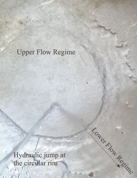
Figure \(\PageIndex{11}\): Formation of a hydraulic jump in the laundry sink. The transition across the circular rim marks the change from Upper to Lower Flow Regime. (Brian Ricketts photo.)
You can generate a hydraulic jump in your kitchen or laundry sink, so long as the sink floor is reasonably flat. Turn on the tap until you see a flow pattern like the one in the photograph at left. Flat laminar flow is generated by the downward force of tap water – this is the plane bed. The hydraulic jump is located at the circular ridge where the flow changes abruptly. Beyond the jump is lower flow regime flow.
We can use the Flow Regime concept in the field as a qualitative indicator of changes in flow conditions with time (i.e., stratigraphically) and space (laterally). For example, a succession of strata that contains a bed of ripples overlain by larger trough crossbeds indicates that flow velocities, and hence stream power increased abruptly. What kind of paleoenvironment could this have occurred in? This is one of the central questions for any sedimentological analysis.
Some common sedimentary structures, their hydraulic significance, and the environments in which they typically are found, are illustrated below.
A short movie of dune-ripple formation
The link here takes you to a short movie of subaqueous dunes forming in a flume (a flume is a narrow tank containing a sand bed, where the velocity of water flow that can be controlled – they are used in experiments to observe the formation of bedforms, and for modelling engineering problems such as the flow of water around bridge foundations). Flow in this experiment is Lower Flow Regime. The sequence begins by showing water flow in front of the migrating lee face; look carefully and you will notice (movie presented by Michael Calzi, SUNY Genseo Dept. of Geological Science):
- sand grains being carried along the stoss slope bed;
- when grains reach the dune crest, they avalanche down the lee face – forming crossbed foresets,
- water flow downstream of the lee face appears to flow backwards – this is the backflow shown schematically in the ripple formation diagram above.