1.5: Folds
- Page ID
- 12509
\( \newcommand{\vecs}[1]{\overset { \scriptstyle \rightharpoonup} {\mathbf{#1}} } \)
\( \newcommand{\vecd}[1]{\overset{-\!-\!\rightharpoonup}{\vphantom{a}\smash {#1}}} \)
\( \newcommand{\dsum}{\displaystyle\sum\limits} \)
\( \newcommand{\dint}{\displaystyle\int\limits} \)
\( \newcommand{\dlim}{\displaystyle\lim\limits} \)
\( \newcommand{\id}{\mathrm{id}}\) \( \newcommand{\Span}{\mathrm{span}}\)
( \newcommand{\kernel}{\mathrm{null}\,}\) \( \newcommand{\range}{\mathrm{range}\,}\)
\( \newcommand{\RealPart}{\mathrm{Re}}\) \( \newcommand{\ImaginaryPart}{\mathrm{Im}}\)
\( \newcommand{\Argument}{\mathrm{Arg}}\) \( \newcommand{\norm}[1]{\| #1 \|}\)
\( \newcommand{\inner}[2]{\langle #1, #2 \rangle}\)
\( \newcommand{\Span}{\mathrm{span}}\)
\( \newcommand{\id}{\mathrm{id}}\)
\( \newcommand{\Span}{\mathrm{span}}\)
\( \newcommand{\kernel}{\mathrm{null}\,}\)
\( \newcommand{\range}{\mathrm{range}\,}\)
\( \newcommand{\RealPart}{\mathrm{Re}}\)
\( \newcommand{\ImaginaryPart}{\mathrm{Im}}\)
\( \newcommand{\Argument}{\mathrm{Arg}}\)
\( \newcommand{\norm}[1]{\| #1 \|}\)
\( \newcommand{\inner}[2]{\langle #1, #2 \rangle}\)
\( \newcommand{\Span}{\mathrm{span}}\) \( \newcommand{\AA}{\unicode[.8,0]{x212B}}\)
\( \newcommand{\vectorA}[1]{\vec{#1}} % arrow\)
\( \newcommand{\vectorAt}[1]{\vec{\text{#1}}} % arrow\)
\( \newcommand{\vectorB}[1]{\overset { \scriptstyle \rightharpoonup} {\mathbf{#1}} } \)
\( \newcommand{\vectorC}[1]{\textbf{#1}} \)
\( \newcommand{\vectorD}[1]{\overrightarrow{#1}} \)
\( \newcommand{\vectorDt}[1]{\overrightarrow{\text{#1}}} \)
\( \newcommand{\vectE}[1]{\overset{-\!-\!\rightharpoonup}{\vphantom{a}\smash{\mathbf {#1}}}} \)
\( \newcommand{\vecs}[1]{\overset { \scriptstyle \rightharpoonup} {\mathbf{#1}} } \)
\(\newcommand{\longvect}{\overrightarrow}\)
\( \newcommand{\vecd}[1]{\overset{-\!-\!\rightharpoonup}{\vphantom{a}\smash {#1}}} \)
\(\newcommand{\avec}{\mathbf a}\) \(\newcommand{\bvec}{\mathbf b}\) \(\newcommand{\cvec}{\mathbf c}\) \(\newcommand{\dvec}{\mathbf d}\) \(\newcommand{\dtil}{\widetilde{\mathbf d}}\) \(\newcommand{\evec}{\mathbf e}\) \(\newcommand{\fvec}{\mathbf f}\) \(\newcommand{\nvec}{\mathbf n}\) \(\newcommand{\pvec}{\mathbf p}\) \(\newcommand{\qvec}{\mathbf q}\) \(\newcommand{\svec}{\mathbf s}\) \(\newcommand{\tvec}{\mathbf t}\) \(\newcommand{\uvec}{\mathbf u}\) \(\newcommand{\vvec}{\mathbf v}\) \(\newcommand{\wvec}{\mathbf w}\) \(\newcommand{\xvec}{\mathbf x}\) \(\newcommand{\yvec}{\mathbf y}\) \(\newcommand{\zvec}{\mathbf z}\) \(\newcommand{\rvec}{\mathbf r}\) \(\newcommand{\mvec}{\mathbf m}\) \(\newcommand{\zerovec}{\mathbf 0}\) \(\newcommand{\onevec}{\mathbf 1}\) \(\newcommand{\real}{\mathbb R}\) \(\newcommand{\twovec}[2]{\left[\begin{array}{r}#1 \\ #2 \end{array}\right]}\) \(\newcommand{\ctwovec}[2]{\left[\begin{array}{c}#1 \\ #2 \end{array}\right]}\) \(\newcommand{\threevec}[3]{\left[\begin{array}{r}#1 \\ #2 \\ #3 \end{array}\right]}\) \(\newcommand{\cthreevec}[3]{\left[\begin{array}{c}#1 \\ #2 \\ #3 \end{array}\right]}\) \(\newcommand{\fourvec}[4]{\left[\begin{array}{r}#1 \\ #2 \\ #3 \\ #4 \end{array}\right]}\) \(\newcommand{\cfourvec}[4]{\left[\begin{array}{c}#1 \\ #2 \\ #3 \\ #4 \end{array}\right]}\) \(\newcommand{\fivevec}[5]{\left[\begin{array}{r}#1 \\ #2 \\ #3 \\ #4 \\ #5 \\ \end{array}\right]}\) \(\newcommand{\cfivevec}[5]{\left[\begin{array}{c}#1 \\ #2 \\ #3 \\ #4 \\ #5 \\ \end{array}\right]}\) \(\newcommand{\mattwo}[4]{\left[\begin{array}{rr}#1 \amp #2 \\ #3 \amp #4 \\ \end{array}\right]}\) \(\newcommand{\laspan}[1]{\text{Span}\{#1\}}\) \(\newcommand{\bcal}{\cal B}\) \(\newcommand{\ccal}{\cal C}\) \(\newcommand{\scal}{\cal S}\) \(\newcommand{\wcal}{\cal W}\) \(\newcommand{\ecal}{\cal E}\) \(\newcommand{\coords}[2]{\left\{#1\right\}_{#2}}\) \(\newcommand{\gray}[1]{\color{gray}{#1}}\) \(\newcommand{\lgray}[1]{\color{lightgray}{#1}}\) \(\newcommand{\rank}{\operatorname{rank}}\) \(\newcommand{\row}{\text{Row}}\) \(\newcommand{\col}{\text{Col}}\) \(\renewcommand{\row}{\text{Row}}\) \(\newcommand{\nul}{\text{Nul}}\) \(\newcommand{\var}{\text{Var}}\) \(\newcommand{\corr}{\text{corr}}\) \(\newcommand{\len}[1]{\left|#1\right|}\) \(\newcommand{\bbar}{\overline{\bvec}}\) \(\newcommand{\bhat}{\widehat{\bvec}}\) \(\newcommand{\bperp}{\bvec^\perp}\) \(\newcommand{\xhat}{\widehat{\xvec}}\) \(\newcommand{\vhat}{\widehat{\vvec}}\) \(\newcommand{\uhat}{\widehat{\uvec}}\) \(\newcommand{\what}{\widehat{\wvec}}\) \(\newcommand{\Sighat}{\widehat{\Sigma}}\) \(\newcommand{\lt}{<}\) \(\newcommand{\gt}{>}\) \(\newcommand{\amp}{&}\) \(\definecolor{fillinmathshade}{gray}{0.9}\)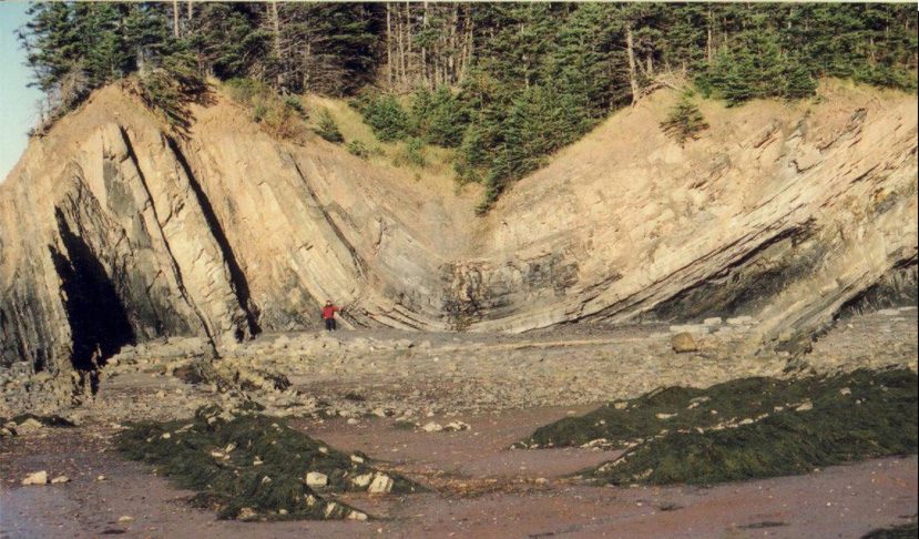
Introduction
Folds are some of the most striking and spectacular features of the Earth’s crust. In most cases, folds form where layered rocks have been shortened. Folds are very common, therefore, in orogenic belts – regions where the Earth’s lithosphere has undergone shortening as a result of plate movements. Orogenic belts often form mountain ranges.
Folds are important economically. Many petroleum traps are located in anticlines. Similarly, gold-bearing quartz veins in several major goldfields were emplaced in spaces (saddle reefs) that opened between layers during folding.
As with all structures, we will emphasize geometry first, and then venture into kinematics and dynamics once we have a firm descriptive framework.
Folds are very variable in style. Thus there are many features to describe and measure in typical folded rocks. In the sections that follow, we will distinguish between variant and invariant features of folds. Invariant features are independent of fold orientation, whereas variant features depend on the orientation of a fold. Invariant features are underlined when they are first introduced in the following sections.
All the terms in the following sections are equally applicable to folds at microscopic, outcrop, and map-scale.
Geometric description of single folded surfaces
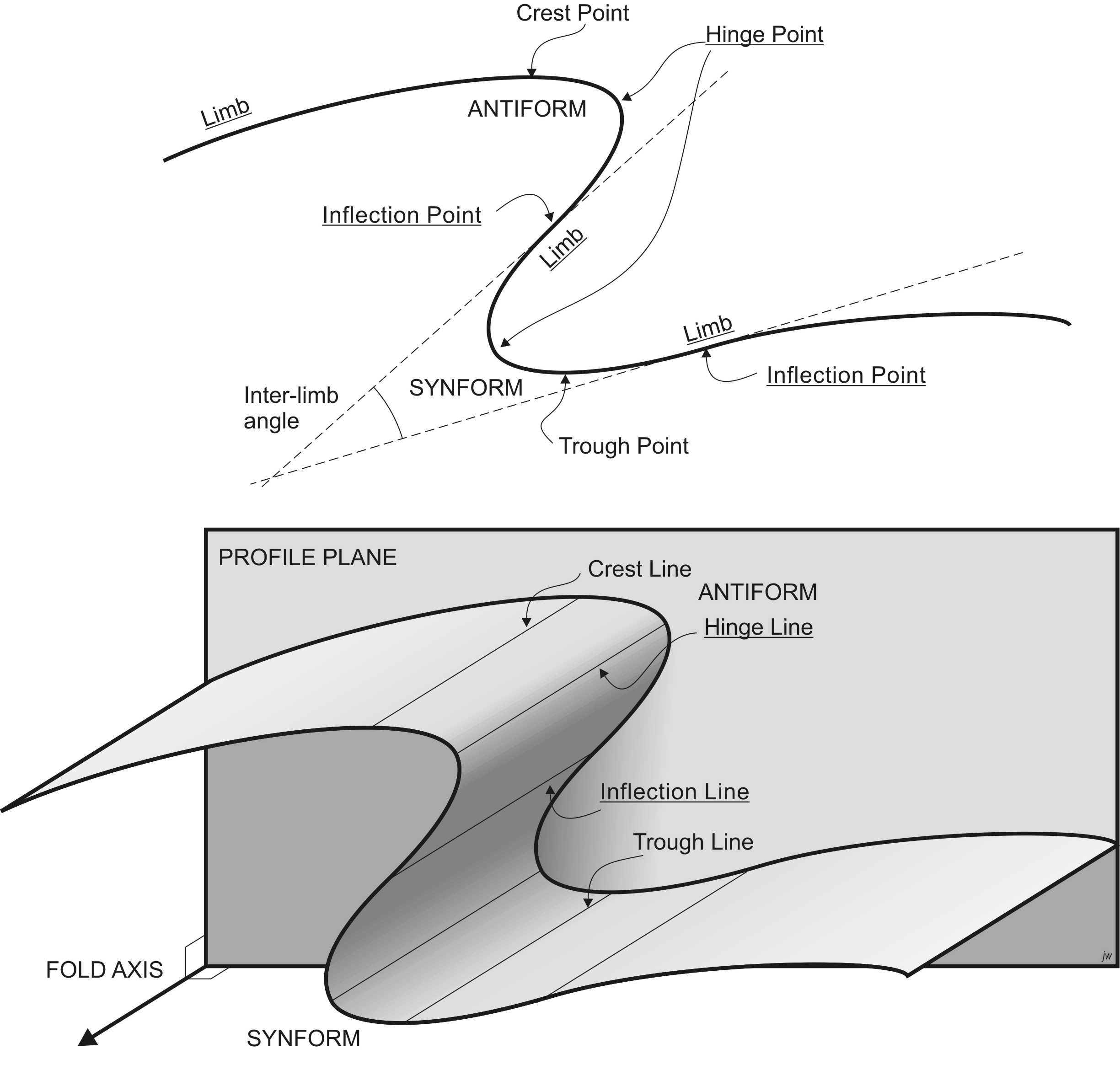
The simplest drawing of a folded surface is in profile view: an ‘end on’ view of the fold. Technically, the profile view is a view projected onto a plane perpendicular to the fold hinge.
Single folded surfaces in profile
Invariant points
Points of tightest curvature are hinges, located in the hinge region. Points of minimum curvature are inflection points which are located on fold limbs. If a tangent is drawn at the inflection point on each limb of a fold, the tangents intersect at the inter-limb angle.
Inter-limb angle
Folds can be classified by inter-limb angle as:
| Category | Inter-limb angle |
| Gentle | 180 – 170° |
| Open | 170 – 90° |
| Tight | 90 – 10° |
| Isoclinal | 10 – 0° |
| Ptygmatic or Fan | < 0° |
Note that there are several different schemes for defining these categories. The above scheme is that given in the text by Davis et al. (2011).
Fold shape
Based on their shape, fold hinges can be classified as angular or rounded. (There are more sophisticated classifications but these will do for our purposes.)
Closing direction: synforms and antiforms
If the limbs dip away from the hinge, then the fold closes upward; we say the fold is an antiform. If the limbs dip towards the hinge, then the fold closes downward, and the fold is a synform.
Notice that if a fold closes ‘sideways’ so that one limb dips toward the hinge and the other dips away, it’s not possible to define it as either an antiform or a synform. (We will meet the term ‘recumbent’ which is helpful in describing such folds, in a later subsection.)
Also in profile, we can identify the highest point on the trace of an antiform, called a crest point. The lowest point on the trace of a synform is called a trough point. Note that the crest and trough points do not necessarily coincide with the hinge points, except in perfectly angular, or perfectly upright folds.
Younging direction: synclines and anticlines
A folded surface in sedimentary rocks has a stratigraphic top side and a stratigraphic bottom side. These define the younging direction. If the younging direction is towards the inside of the fold, then the fold is a syncline. If the younging direction is away from the inside of the fold, then the fold is an anticline.
In areas of mild deformation like the Rocky Mountain foothills, where the rocks are regionally the right way up, anticlines are antiforms; the terms can be used more or less interchangeably. Similarly, in such areas synclines are also synforms.
However, in areas like the interior of the Cordillera, or the Alps of Europe, there are regions where the rocks are upside down over large areas. There, it’s possible for antiforms to be synclines and synforms to be anticlines. Therefore it is important that if you don’t know the younging direction for sure, use only the terms antiform and synform to describe the fold geometry!
Possible combinations of closing and younging direction:
| Antiform | Synform | |
| Anticline | Antiformal anticline | Synformal anticline |
| Syncline | Antiformal syncline | Synformal syncline |
Single folded surfaces in 3-D
In 3-D all the variant and invariant points can be extended into lines.
Hinge line: a line representing the locus of maximum curvature (i.e. joining all the hinge points.) The plane perpendicular to the fold hinge is called the profile plane. It’s the plane on which we draw a profile view of a fold.
We also recognize inflection lines, crest lines and trough lines.
In very regular folds, all these lines are straight and parallel (they have the same trend and plunge). Indeed all planes measured on such folds are parallel to this unique generating line. We describe such folds as cylindrical, and the direction of the unique line is the fold axis.
Not all folds are cylindrical, however. In non-cylindrical folds the hinge lines, inflection lines, trough lines and crest lines may be curved and irregular. The highest point on a crest line is described as a culmination point; layers dip away from a culmination point in all directions. A culmination point is often an attractive target for petroleum drilling. The lowest point on a trough line is a depression point. Layers dip towards the depression point in all directions. If a culmination point is particularly symmetrical, such that the dip increases at about the same rate in all directions, then the fold is a structuraldome. The opposite of a dome, a fold with a symmetrical trough point, is a structuralbasin. Structural domes and basins are sometimes described as periclines.
Fold attitude
All the lines in a fold have a trend and plunge; in cylindrical folds these are all the same – the fold axis orientation. In non-cylindrical folds, the easiest and most regularly measured feature is the hinge line. We can classify folds by hinge-line plunge as follows:
| Plunge | Classification by hinge-line plunge |
| 0-10° | Subhorizontal |
| 10-30° | Gently plunging |
| 30-60° | Moderately plunging |
| 60-80° | Steeply plunging |
| 80-90° | Subvertical |
Trains of folds in profile and 3-D
The above terms apply to single folds. Commonly, multiple folds are observed in the same folded surface, in which case certain patterns are common.
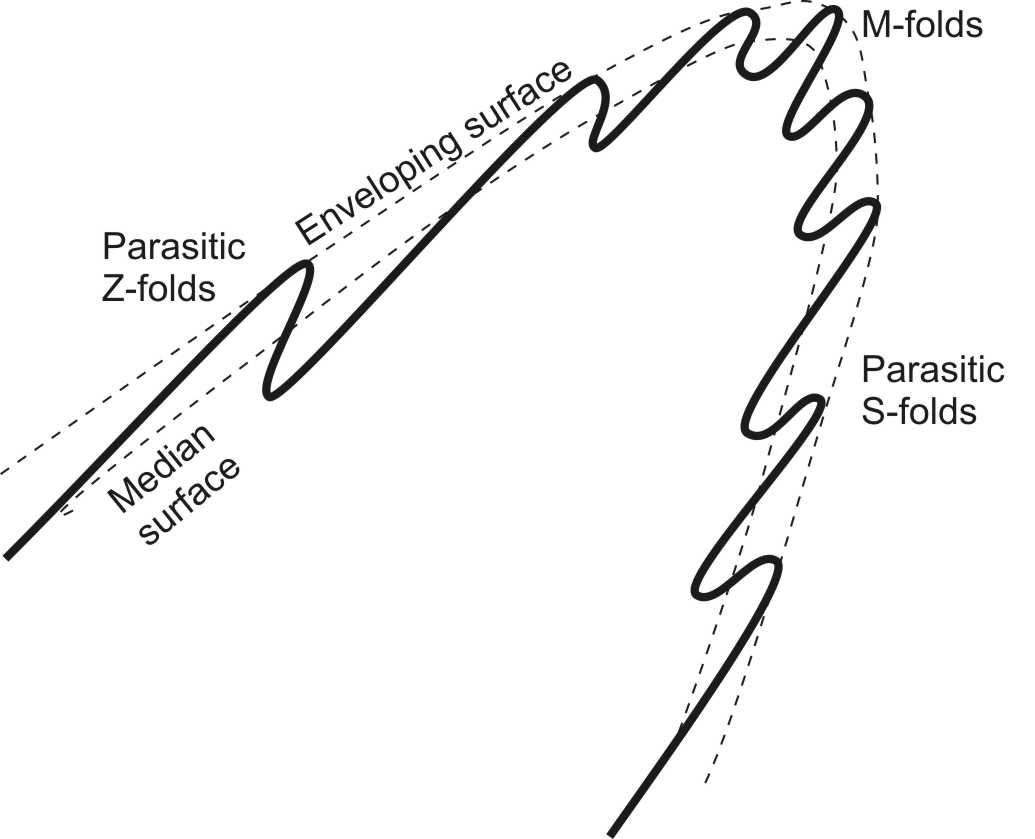
If we draw a surface that is tangent to all the folds, it is called an enveloping surface. Similarly, the surface that passes through all the inflection lines is a median surface.
Many folded surfaces show alternating long limbs and short limbs, making the folds asymmetric. This asymmetry allows folds to be labelled as either S-folds or Z-folds. To determine whether a fold train has S or Z asymmetry look at three limbs with a long-short-long sequence. If the 3 limbs have the asymmetry of the letter Z then this is a Z-fold; if the limbs have the asymmetry of the letter S then the fold is an S-fold. Note that this has nothing to do with the fact that the S is rounded and the Z is angular; it is the rotational symmetry that is important.
A fold that has S-asymmetry when viewed from one end has Z asymmetry from the other. Therefore it is important that we say which way we are looking when we characterize a fold as S or Z. If the direction of viewing is unspecified, then the convention is to look in the down-plunge direction.
One common occurrence of S and Z folds is when folds occur at different scales in the same layer. Small folds developed on the limbs of larger folds, with the same orientation, are called parasitic folds (Fig. 2). Typically, parasitic folds on one limb have S asymmetry whereas those on the other limb have Z asymmetry. There is often a region on the hinge where parasitic folds have no clear asymmetry; they are described as M (or W) folds. Sometimes mapping the asymmetry of outcrop-scale parasitic folds is a good way to locate the hinges of less obvious map-scale major folds.
Features of successive surfaces
It is rare to see just a single folded surface in outcrop. Most layered rocks have multiple layers that are folded together, which enables us to define some additional variant and invariant features.
In profile
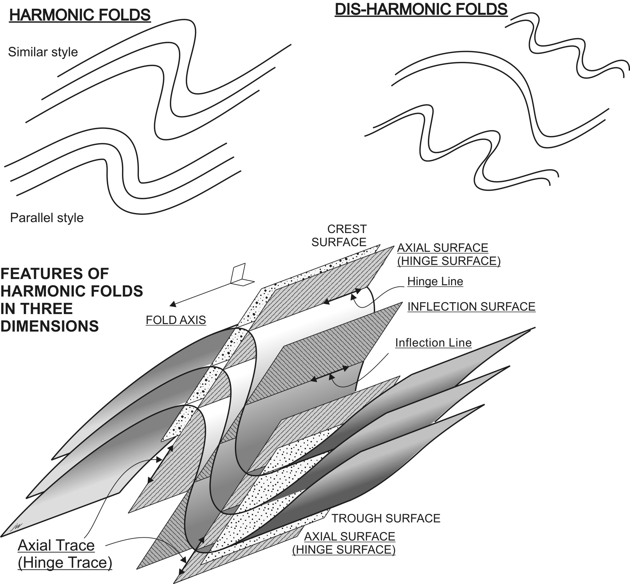
A line drawn through all the hinge points of a fold is called the axial trace of the fold. (It’s also called the hinge trace, which is arguably a better term because the trace has little relation to the fold axis, but most structural geologists use axial trace.)
The other variant and invariant points also correspond to traces on the profile plane: inflection trace, crest trace, trough trace. (Because all these lines are the traces, on the profile plane, of surfaces in 3-D, the word ‘surface’ is sometimes added: inflection surface trace, crest surface trace, trough surface trace.)
In 3-D
By now you can anticipate that in 3-D each of the lines that we identified on a single surface can be extrapolated into a surface in 3D.
The most important surface is the axial surface (or hinge surface). This surface is of great kinematic significance because the pole to the axial surface is often the direction of maximum shortening.
The other surfaces: inflection surface, crest surface, and trough surface are all parallel to the axial surface in a cylindrical fold.
The facing direction is the direction of younging in the fold axial surface. It is perpendicular to fold hinges but lies in the axial surface. Notice that folds may have overturned limbs but still face upward.
The relationship of facing direction to anticlines, synclines, antiforms, and synforms:
| ANTIFORM | SYNFORM | |
| ANTICLINE | Antiformal anticline | Synformal anticline |
| (Upward facing) | (Downward facing) | |
| SYNCLINE | Antiformal syncline | Synformal syncline |
| (Downward facing) | (Upward facing) |
Notice that in upward facing folds the ‘-form’ and the ‘-cline’ are the same. In downward facing folds the ‘-form’ and ‘-cline’ are different.
Fold attitude
Because of its kinematic significance, the strike and dip of the axial surface are important features to measure in an outcrop of a fold. Folds can be classified by axial surface orientation:
| Dip | Classification by axial-surface dip |
| 0-10° | Recumbent |
| 10-30° | Gently inclined |
| 30-60° | Moderately inclined |
| 60-80° | Steeply inclined |
| 80-90° | Upright |
Because of the way the axial surface is defined, the hinge of a fold must be a line that lies in the axial surface. This means that the plunge of the hinge cannot be steeper than the dip of the axial surface. It also means that the hinge line has a rake or pitch in the axial surface. There is a special term for folds in which the rake of the hinge in the axial surface is close to 90°: these are reclined folds.
Harmonic and disharmonic folds
All the above features are characteristic of folds where each layer is folded in step with the adjacent layers. These are called harmonic folds. Sometimes we find layered rocks in which the folds are not so aligned. These are disharmonic folds. It’s not usually possible to define axial, inflection, trough, or crest surfaces in disharmonic folds, which therefore provide less information about regional deformation than harmonic folds.

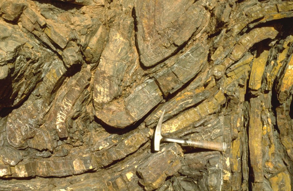
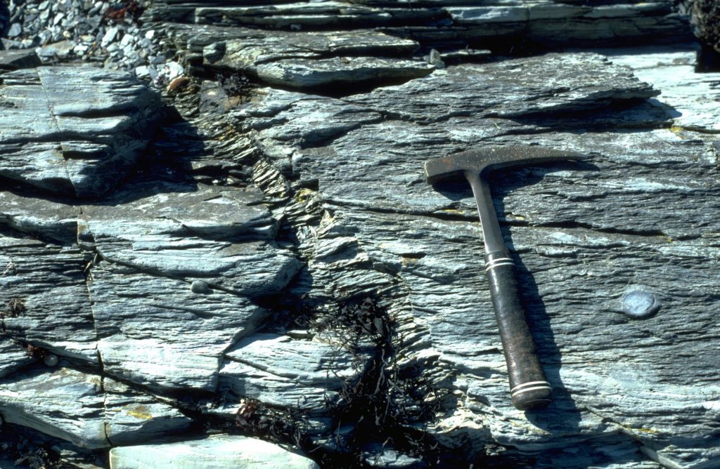
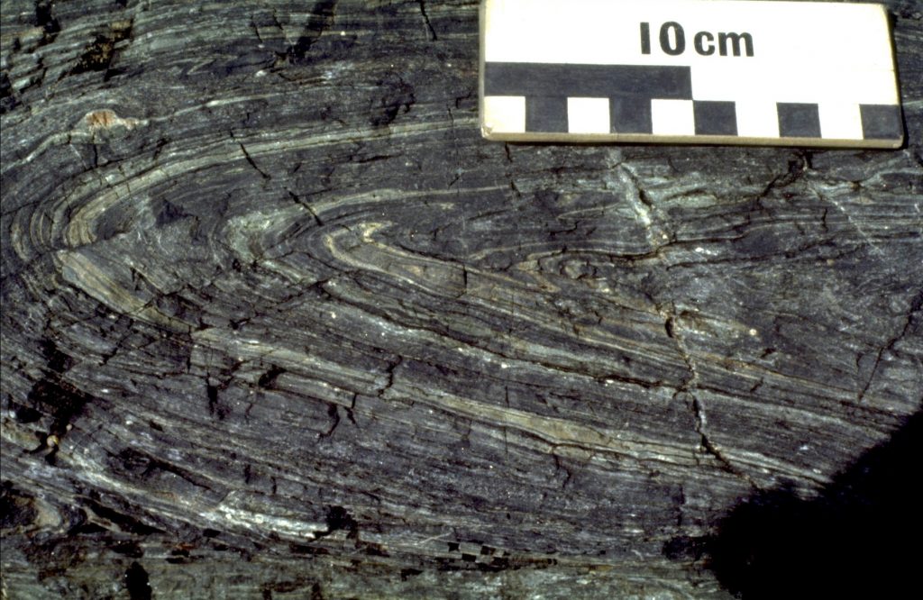
Some common fold styles
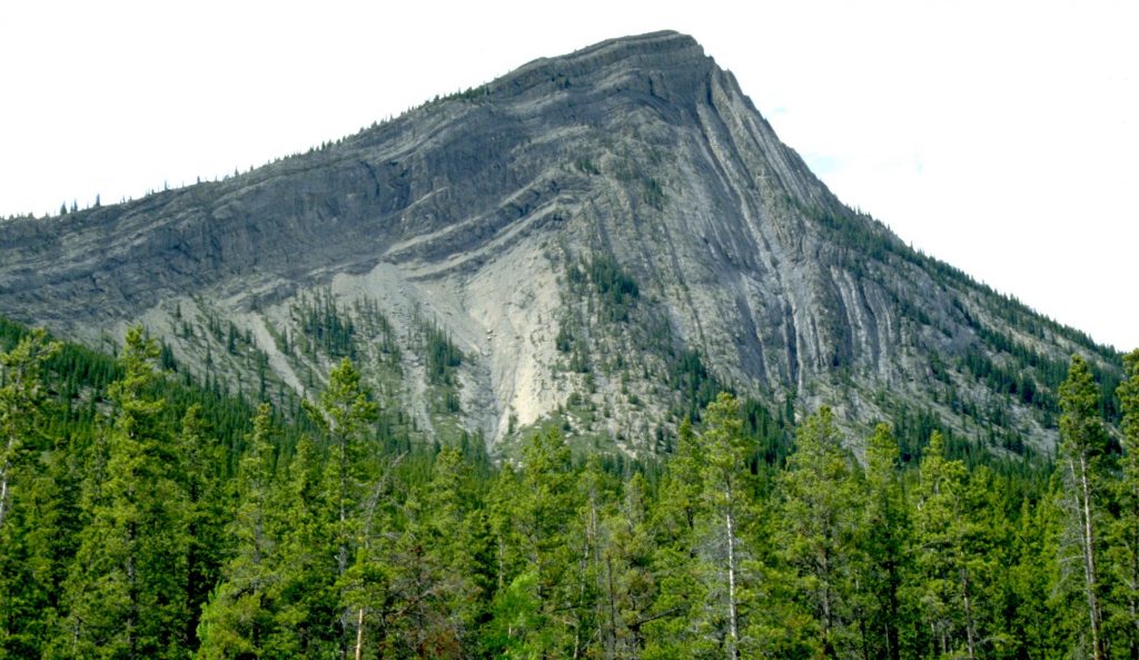
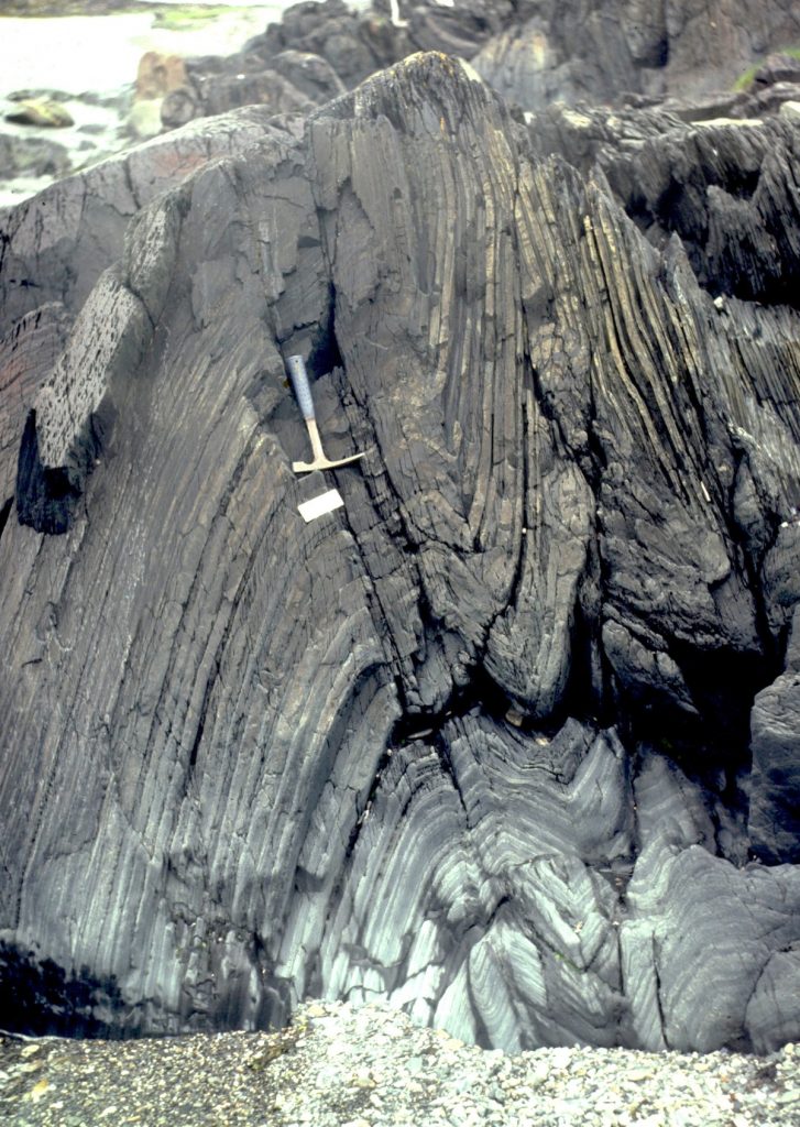
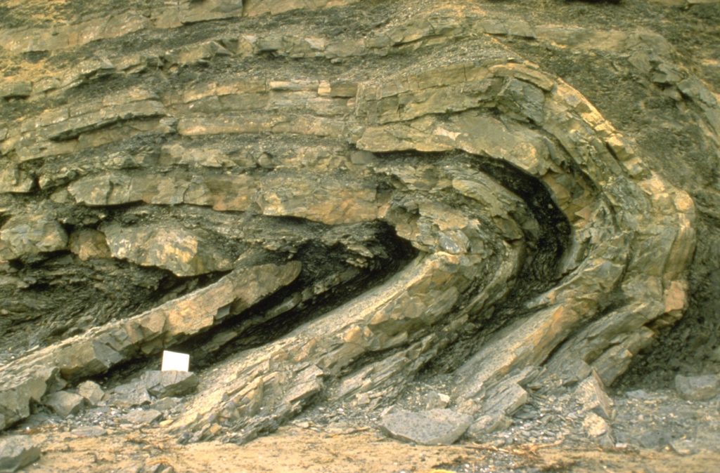
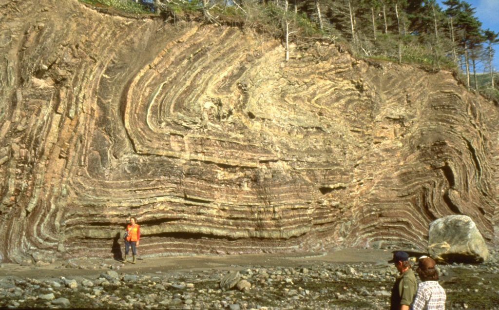
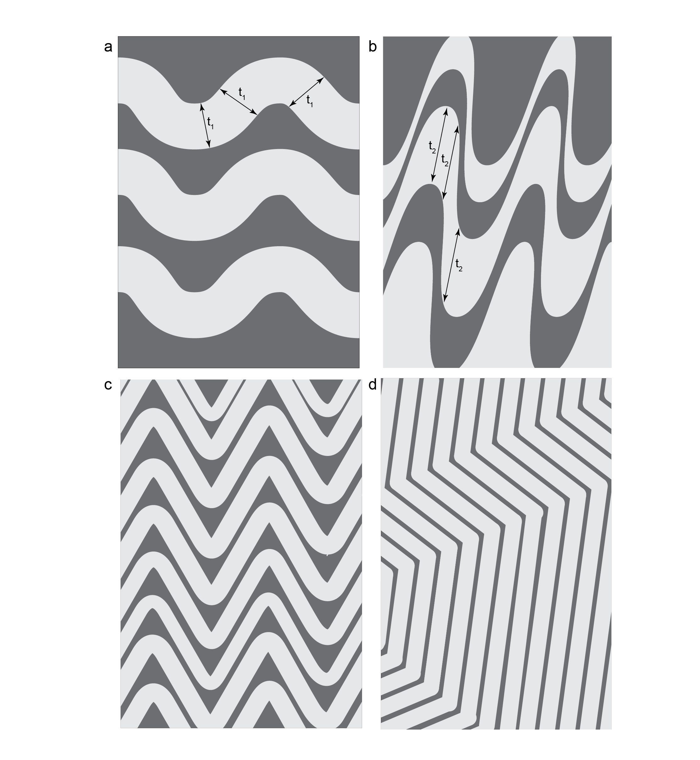
Some types of fold style occur in many circumstances, and can give clues as on the dynamics of folding.. Where layers of strong rock are interlayered with very weak rock, the strong layers may have nearly constant thickness around fold hinges, so that the inner and outer arcs are parallel. Such folds are called parallel or concentric folds. Distinctive styles of parallel folds occur when the strong layers are close together and can slide over each other easily. Under these conditions, very angular folds may develop. When these have inter-limb angles around 60° they are called chevron folds. Inter-limb angles around 120° define kink folds. Conversely, when all the layers are weak, for example in rocks near their melting point, folds may develop in which each folded surface is geometrically similar to the next; these are similar folds.
Folds in map view
Folded rocks are more complicated in map view than simple planar strata, because map patterns result from a combination of hills and valleys in the landscape, and antiforms and synforms in the strata.
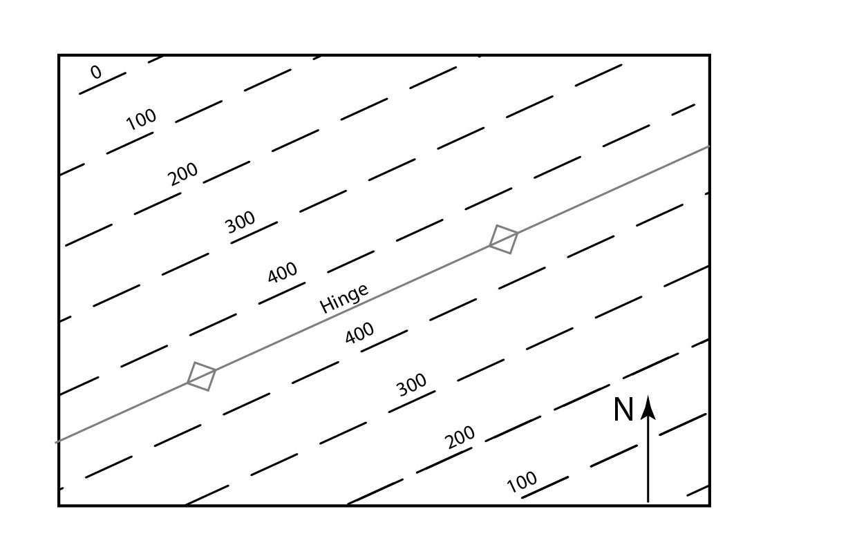
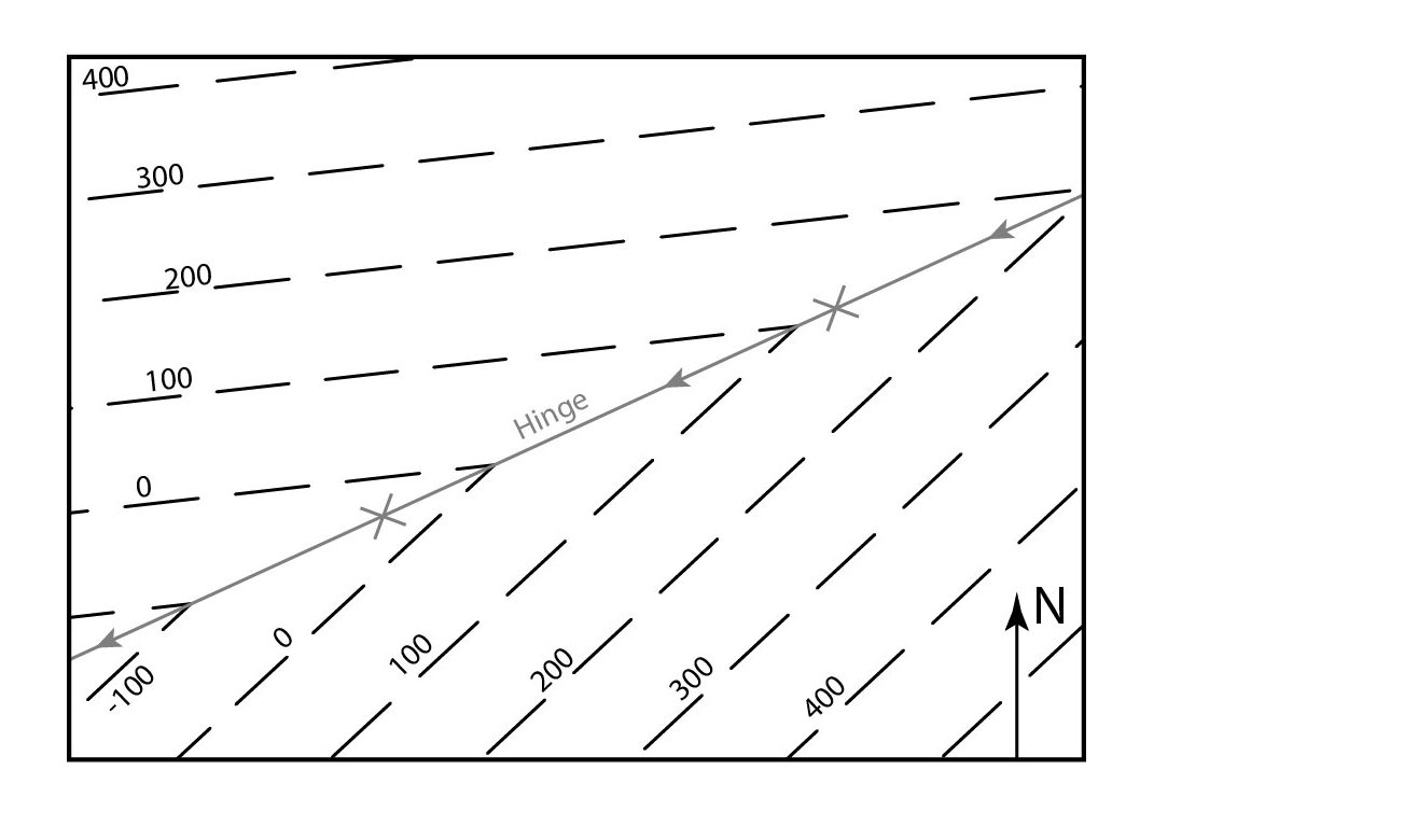
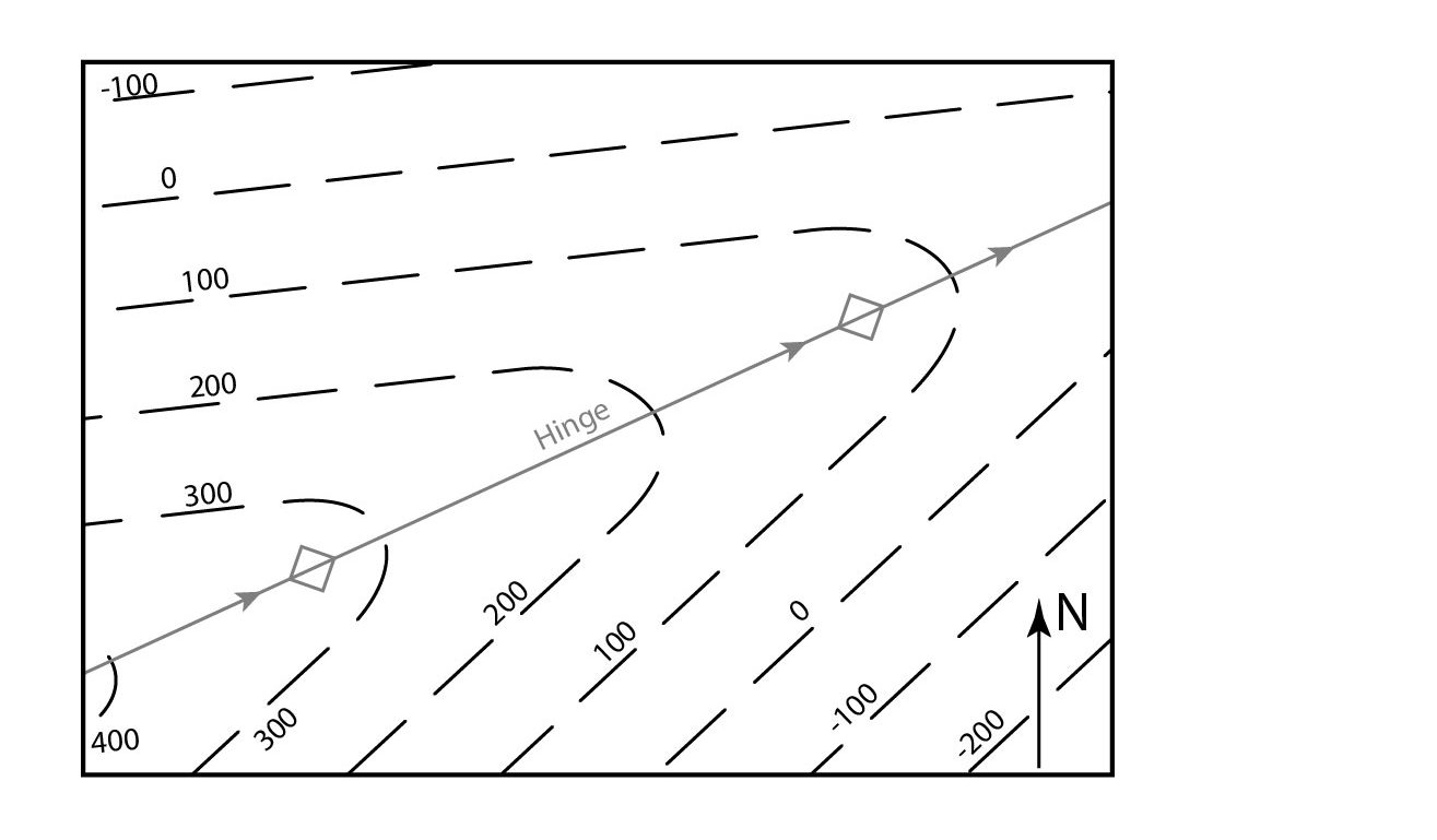
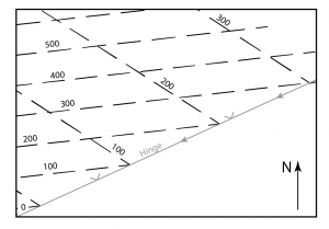
The shape of folded strata can often be figured out with structure contours, but unlike those for simple planar strata, structure contours for folded strata are not straight. They show angles or curves. Some examples are shown in the following diagrams.
If the fold hinges are perfectly horizontal, the structure contours will remain straight and parallel, but the numbers will show changes of dip:
However, if the fold plunges, the contours themselves will V-shaped, in the case of an angular fold:
If the fold is rounded, the structure contours will be curved, showing U-shapes:
If the fold is overturned, the contours will again be V or U-shaped but contours for both limbs will occur on the same side of the fold hinge:
Fold overprinting
Areas affected by multiple episodes of folding may display refolded folds in a bewildering variety of orientations, producing a variety of fold interference patterns.
Classification of fold interference patterns
To make sense of these we use a classification (devised, like many other fundamental classifications of folds, by J. Ramsay, 1967). This classification relates to two generations of folds only – if we have 3 or more generations things get more complicated.
In each case we characterize a first generation of folds by
- an axial surface
- a fold hinge that lies in that axial surface
We examine the effect of the second generation of folds on those two structures.
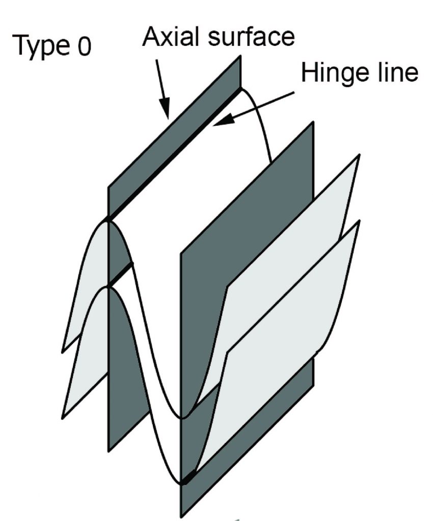
If later folding does not bend either the axial surfaces or the hinges of early folds, then the early folds are effectively just tightened during the second phase of deformation. The fold pattern is described as ‘type 0’, and generally it will not be apparent from geometry that there have been two phases of deformation.
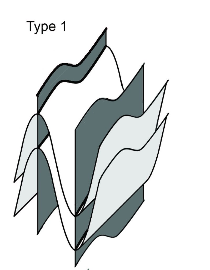
If later shortening is roughly parallel to the hinges of the early folds, and the extension direction also lies in the early fold axial surfaces, then later folding bends the hinges of the early folds but does not significantly bend the axial surfaces. This typically produces culminations and depressions on the early fold hinges, and leads to oval outcrop patterns of layer traces on outcrop surfaces. This is called a type 1 fold interference pattern, characterized by domes and basins.
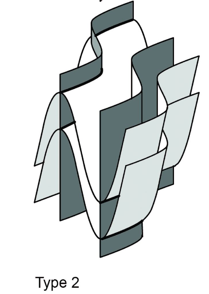
If on the other hand, the extension direction in the second deformation is at a high angle to the early axial surfaces, then those axial surfaces may be folded too. Under these circumstances outcrop patterns are characterized by complex shapes that resemble mushrooms and bananas. This is called a type 2 interference pattern.
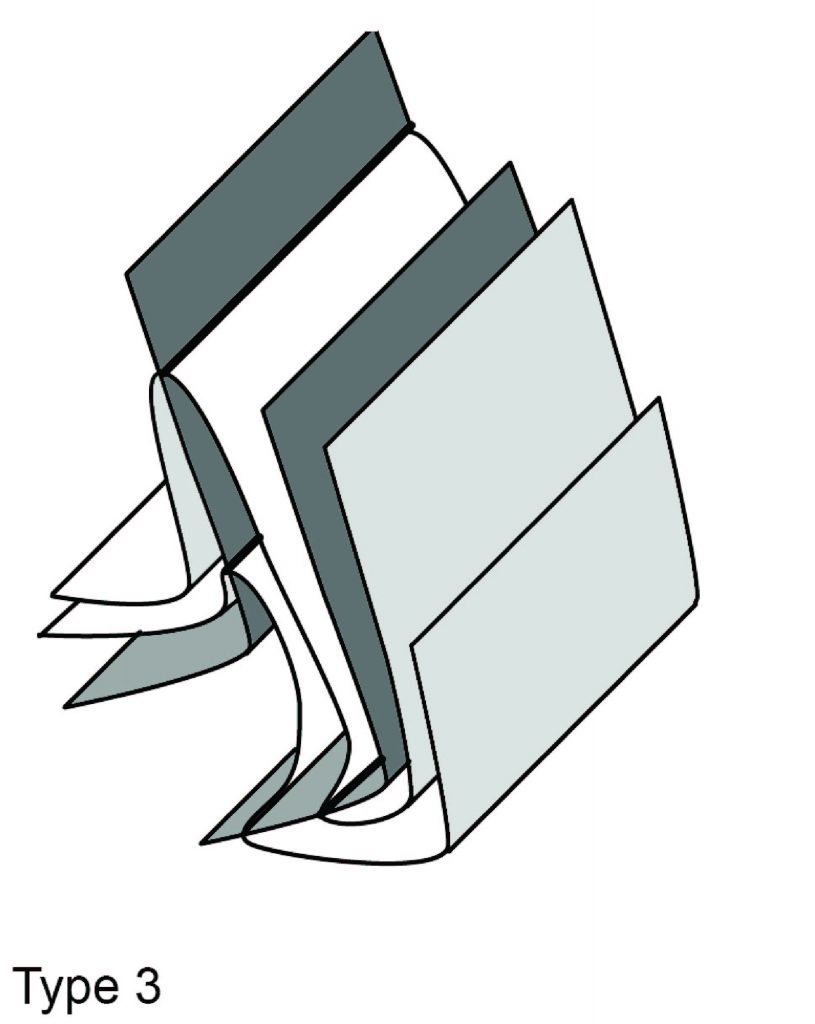
There is a third case, which occurs when the shortening direction is at a high angle to the early fold hinges and the extension direction is at a high angle to the early axial surfaces. Under these conditions the early hinges may remain more or less straight but the early axial surfaces are folded. The trace of layering typically follows a multiple zigzag shape described as a type 3 interference pattern.
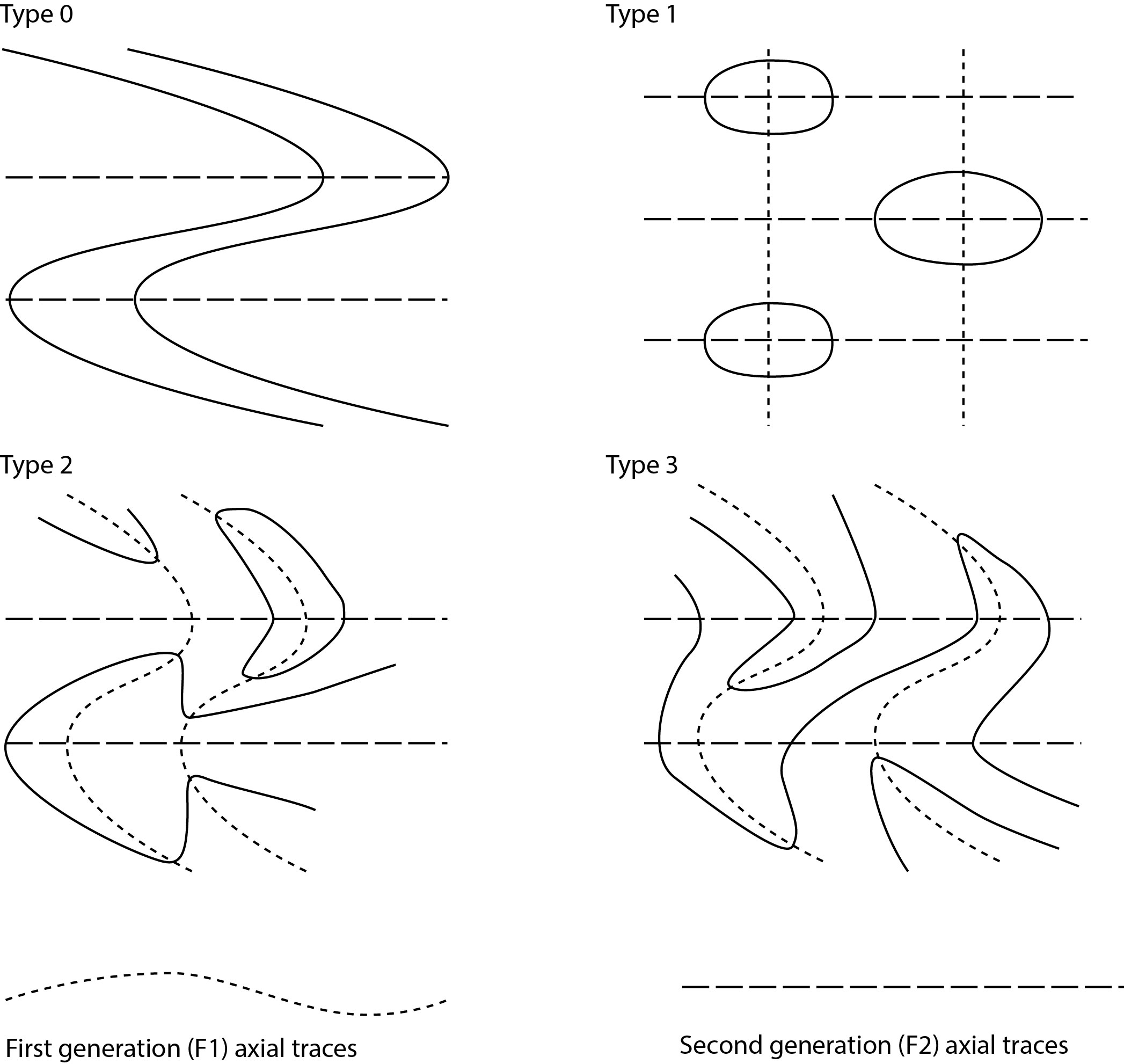
How to analyse an overprinted fold pattern
When trying to understand an overprinted fold pattern, the most important first step is to draw axial traces. In general, the latest set of axial traces is likely to be approximately straight. Earlier axial traces may or may not be folded. (In general, type 1 interference patterns, where early axial surfaces are not folded, are the most difficult to analyze; it may not be possible to determine the order of folding.)
Facing directions may also be useful in the analysis of overprinted folds. For example, downward-facing folds (synformal anticlines and antiformal synclines) always indicate that there are at least two generations of folds.
References
Davis, G.H., Reynolds, S,J. and Kluth, C.F. (2011) Structural Geology of Rocks and Regions, 3rd Edition, Wiley, New York, 864 p.
Ramsay, J.G. (1967) Folding and Fracturing of Rocks: San Francisco, McGraw Hill, 568 p.
Van der Pluijm, B.A. and Marshak, S. (2004) Earth Structure: An Introduction to Structural Geology and Tectonics, Norton, New York, 656 p.


