1.2: Orientation of Structures
- Page ID
- 12503
\( \newcommand{\vecs}[1]{\overset { \scriptstyle \rightharpoonup} {\mathbf{#1}} } \)
\( \newcommand{\vecd}[1]{\overset{-\!-\!\rightharpoonup}{\vphantom{a}\smash {#1}}} \)
\( \newcommand{\id}{\mathrm{id}}\) \( \newcommand{\Span}{\mathrm{span}}\)
( \newcommand{\kernel}{\mathrm{null}\,}\) \( \newcommand{\range}{\mathrm{range}\,}\)
\( \newcommand{\RealPart}{\mathrm{Re}}\) \( \newcommand{\ImaginaryPart}{\mathrm{Im}}\)
\( \newcommand{\Argument}{\mathrm{Arg}}\) \( \newcommand{\norm}[1]{\| #1 \|}\)
\( \newcommand{\inner}[2]{\langle #1, #2 \rangle}\)
\( \newcommand{\Span}{\mathrm{span}}\)
\( \newcommand{\id}{\mathrm{id}}\)
\( \newcommand{\Span}{\mathrm{span}}\)
\( \newcommand{\kernel}{\mathrm{null}\,}\)
\( \newcommand{\range}{\mathrm{range}\,}\)
\( \newcommand{\RealPart}{\mathrm{Re}}\)
\( \newcommand{\ImaginaryPart}{\mathrm{Im}}\)
\( \newcommand{\Argument}{\mathrm{Arg}}\)
\( \newcommand{\norm}[1]{\| #1 \|}\)
\( \newcommand{\inner}[2]{\langle #1, #2 \rangle}\)
\( \newcommand{\Span}{\mathrm{span}}\) \( \newcommand{\AA}{\unicode[.8,0]{x212B}}\)
\( \newcommand{\vectorA}[1]{\vec{#1}} % arrow\)
\( \newcommand{\vectorAt}[1]{\vec{\text{#1}}} % arrow\)
\( \newcommand{\vectorB}[1]{\overset { \scriptstyle \rightharpoonup} {\mathbf{#1}} } \)
\( \newcommand{\vectorC}[1]{\textbf{#1}} \)
\( \newcommand{\vectorD}[1]{\overrightarrow{#1}} \)
\( \newcommand{\vectorDt}[1]{\overrightarrow{\text{#1}}} \)
\( \newcommand{\vectE}[1]{\overset{-\!-\!\rightharpoonup}{\vphantom{a}\smash{\mathbf {#1}}}} \)
\( \newcommand{\vecs}[1]{\overset { \scriptstyle \rightharpoonup} {\mathbf{#1}} } \)
\( \newcommand{\vecd}[1]{\overset{-\!-\!\rightharpoonup}{\vphantom{a}\smash {#1}}} \)
\(\newcommand{\avec}{\mathbf a}\) \(\newcommand{\bvec}{\mathbf b}\) \(\newcommand{\cvec}{\mathbf c}\) \(\newcommand{\dvec}{\mathbf d}\) \(\newcommand{\dtil}{\widetilde{\mathbf d}}\) \(\newcommand{\evec}{\mathbf e}\) \(\newcommand{\fvec}{\mathbf f}\) \(\newcommand{\nvec}{\mathbf n}\) \(\newcommand{\pvec}{\mathbf p}\) \(\newcommand{\qvec}{\mathbf q}\) \(\newcommand{\svec}{\mathbf s}\) \(\newcommand{\tvec}{\mathbf t}\) \(\newcommand{\uvec}{\mathbf u}\) \(\newcommand{\vvec}{\mathbf v}\) \(\newcommand{\wvec}{\mathbf w}\) \(\newcommand{\xvec}{\mathbf x}\) \(\newcommand{\yvec}{\mathbf y}\) \(\newcommand{\zvec}{\mathbf z}\) \(\newcommand{\rvec}{\mathbf r}\) \(\newcommand{\mvec}{\mathbf m}\) \(\newcommand{\zerovec}{\mathbf 0}\) \(\newcommand{\onevec}{\mathbf 1}\) \(\newcommand{\real}{\mathbb R}\) \(\newcommand{\twovec}[2]{\left[\begin{array}{r}#1 \\ #2 \end{array}\right]}\) \(\newcommand{\ctwovec}[2]{\left[\begin{array}{c}#1 \\ #2 \end{array}\right]}\) \(\newcommand{\threevec}[3]{\left[\begin{array}{r}#1 \\ #2 \\ #3 \end{array}\right]}\) \(\newcommand{\cthreevec}[3]{\left[\begin{array}{c}#1 \\ #2 \\ #3 \end{array}\right]}\) \(\newcommand{\fourvec}[4]{\left[\begin{array}{r}#1 \\ #2 \\ #3 \\ #4 \end{array}\right]}\) \(\newcommand{\cfourvec}[4]{\left[\begin{array}{c}#1 \\ #2 \\ #3 \\ #4 \end{array}\right]}\) \(\newcommand{\fivevec}[5]{\left[\begin{array}{r}#1 \\ #2 \\ #3 \\ #4 \\ #5 \\ \end{array}\right]}\) \(\newcommand{\cfivevec}[5]{\left[\begin{array}{c}#1 \\ #2 \\ #3 \\ #4 \\ #5 \\ \end{array}\right]}\) \(\newcommand{\mattwo}[4]{\left[\begin{array}{rr}#1 \amp #2 \\ #3 \amp #4 \\ \end{array}\right]}\) \(\newcommand{\laspan}[1]{\text{Span}\{#1\}}\) \(\newcommand{\bcal}{\cal B}\) \(\newcommand{\ccal}{\cal C}\) \(\newcommand{\scal}{\cal S}\) \(\newcommand{\wcal}{\cal W}\) \(\newcommand{\ecal}{\cal E}\) \(\newcommand{\coords}[2]{\left\{#1\right\}_{#2}}\) \(\newcommand{\gray}[1]{\color{gray}{#1}}\) \(\newcommand{\lgray}[1]{\color{lightgray}{#1}}\) \(\newcommand{\rank}{\operatorname{rank}}\) \(\newcommand{\row}{\text{Row}}\) \(\newcommand{\col}{\text{Col}}\) \(\renewcommand{\row}{\text{Row}}\) \(\newcommand{\nul}{\text{Nul}}\) \(\newcommand{\var}{\text{Var}}\) \(\newcommand{\corr}{\text{corr}}\) \(\newcommand{\len}[1]{\left|#1\right|}\) \(\newcommand{\bbar}{\overline{\bvec}}\) \(\newcommand{\bhat}{\widehat{\bvec}}\) \(\newcommand{\bperp}{\bvec^\perp}\) \(\newcommand{\xhat}{\widehat{\xvec}}\) \(\newcommand{\vhat}{\widehat{\vvec}}\) \(\newcommand{\uhat}{\widehat{\uvec}}\) \(\newcommand{\what}{\widehat{\wvec}}\) \(\newcommand{\Sighat}{\widehat{\Sigma}}\) \(\newcommand{\lt}{<}\) \(\newcommand{\gt}{>}\) \(\newcommand{\amp}{&}\) \(\definecolor{fillinmathshade}{gray}{0.9}\)Lines and Planes
Linear and planar features in geology
Almost all work on geologic structures is concerned in one way or another with lines and planes.
The following are examples of linear features that one might observe in rocks, together with some kinematic deductions from them:
- glacial striae (which reveal the direction of ice movement);
- the fabric or lineation produced by alignment of amphiboles seen in metamorphic rocks (which reveal the direction of stretching acquired during deformation);
- and the alignment of elongate clasts or fossil shells in sedimentary rocks (which reveals current direction).
Examples of planar features include:
- tabular igneous intrusive bodies such as dykes and sills;
- bedding planes in sedimentary rocks;
- the fabric or foliation produced by alignment of sheet silicate minerals such as mica in metamorphic rocks, which reveals the direction of flattening during deformation;
- joints and faults produced by the failure of rocks in response to stress (and which therefore reveal the orientation of stress at some time in the past).
Notice that although several of the above descriptive observations lead to kinematic inferences, only the last one allows us to make dynamic conclusions!
Bearings
To describe almost any structure, we need to say something about its orientation (also known as its attitude): Does it run north-south, or perhaps east-west, or somewhere in between? A direction relative to north is called a bearing. In most geologic work, bearings are specified as azimuths.
An azimuth is a bearing measured clockwise from north.
An azimuth of 000° represents north, 087° is just a shade north of east, 225° represents southwest, and 315° represents NW.
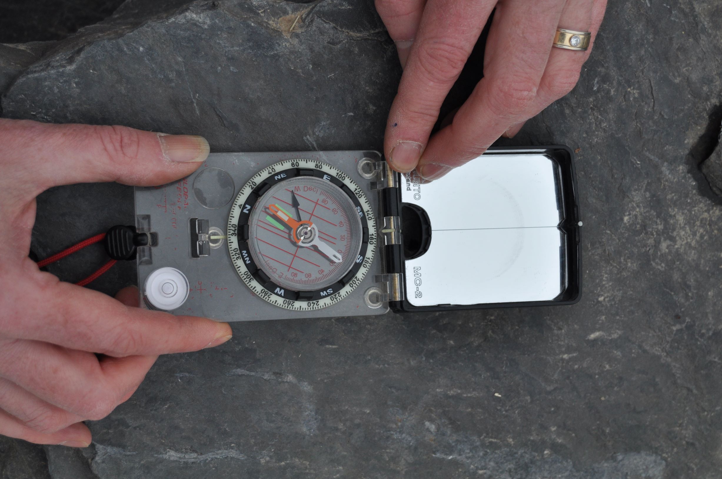
Notice that it is best to use a three digit number for azimuths. This helps to avoid confusion with inclinations (below). The degree symbol is often omitted when recording large numbers of azimuths.
Confusingly, there are other methods of specifying an azimuth. In the United States, bearings are often specified using quadrants.
In the quadrants method of measuring bearings, angles are measured starting at either due north or due south (whichever is closest), and measured by counting degrees toward the east or west.
Here are the four azimuths above, converted to the quadrants representation:
000° N00E
087° N87E
225° S45W
315° N45W
Because it is more confusing, especially when doing calculations, we will not use the quadrants method much in this manual. However, you need to be prepared to understand measurements recorded as quadrants, especially when reading books and geologic reports published in the U.S.
Azimuths are typically measured with a compass, which uses the Earth’s magnetic field as a reference direction. In most parts of the Earth, the magnetic field is not aligned exactly north-south.
The magnetic declination is the azimuth of the Earth’s magnetic field.
Magnetic declination varies from place to place and varies slowly over time. Currently (2020) the declination in Edmonton is about 014°.
Most geological compasses have a mechanism for compensating for declination. Of course, the compass must be adjusted for the particular area in which you are working.
Inclinations
Another type of measurement is often used in structural geology:
An inclination is an angle of slope measured downward relative to horizontal.
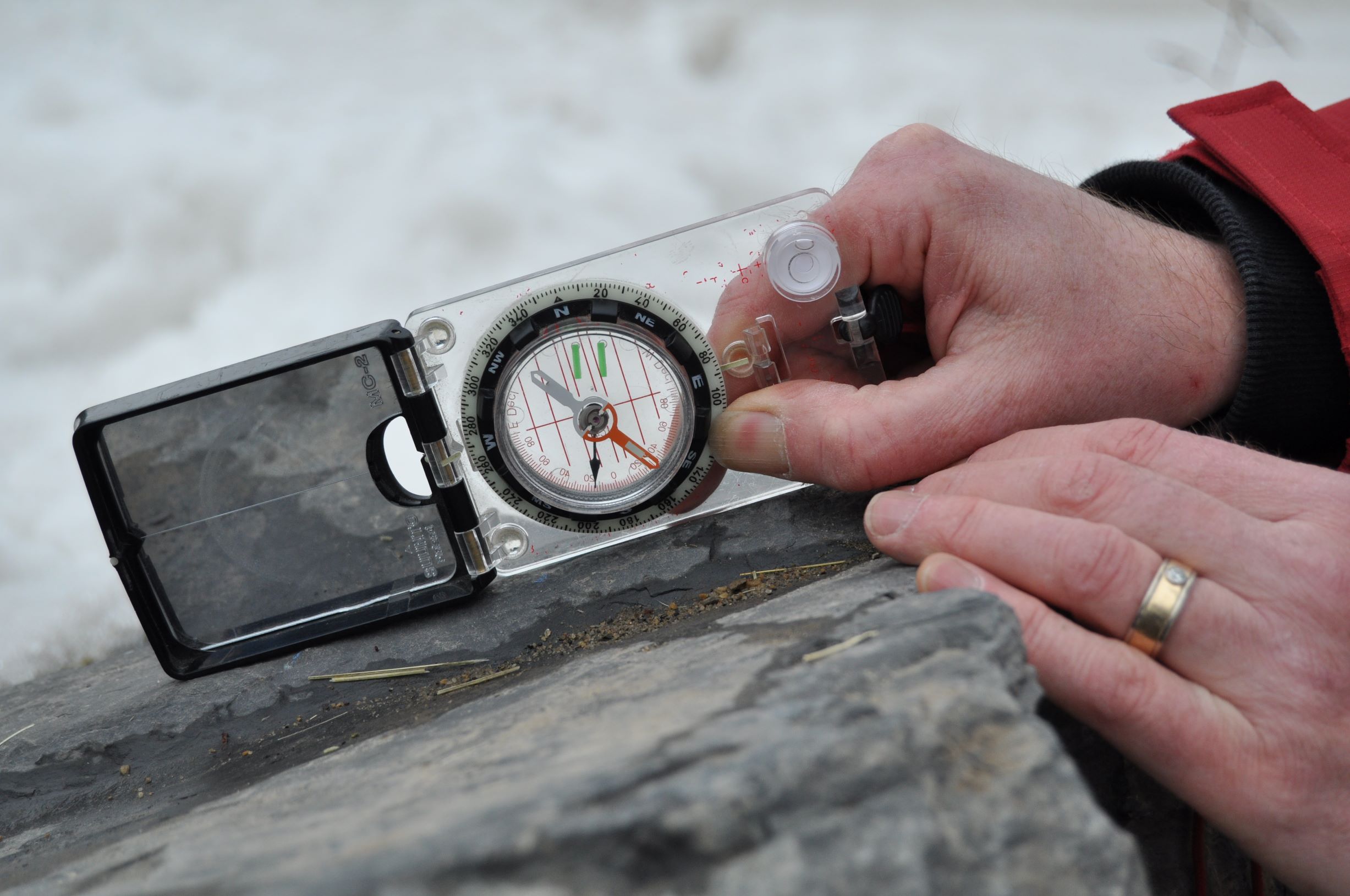
A horizontal line has an inclination of 00°, and a vertical one is inclined 90°. Always use two digits for inclination, to distinguish inclinations from azimuths (three digits).
Inclinations are measured using a device called a clinometer or inclinometer. Geological compasses typically have a built-in clinometer, so one instrument can be used for measuring both types of angle. However, you must hold the compass differently in each case:
To measure an azimuth precisely, using the Earth’s magnetic field, you must hold the compass horizontal;
To measure an inclination, you are using the Earth’s gravity field, and the compass must be held in a vertical plane.
Orientation of a line
To specify the orientation of a line requires two measurements, called plunge and trend:
The plunge of a line is its inclination, measured downward relative to horizontal;
The trend of a line is its azimuth, measured in the direction of plunge.
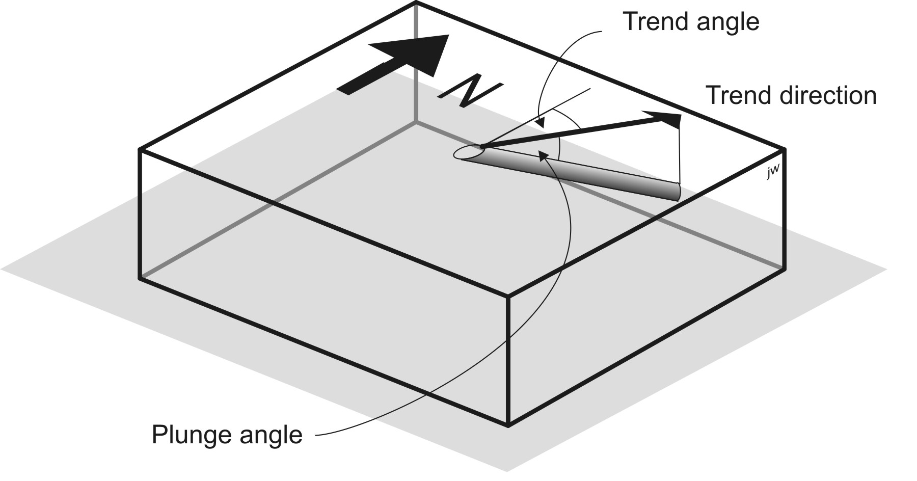
So, a line with plunge 07 and trend 007 slopes downward very gently in a direction just east of north. 227-87 specifies a line that plunges very steeply towards the SW.
There are several different conventions for writing plunge and trend measurements: some geologists write the plunge first and some write it second. The best way to keep things clear is to always use three digits for the trend and two for the plunge. In addition, it’s sometimes helpful to specify the compass direction, just as a check, e.g.
025-37 NE
Orientation of a plane
To specify the orientation of a plane, we also need two measurements, an azimuth and an inclination. The dip of a plane is its inclination. It’s important when measuring dip to measure the steepest possible slope in the plane. If you are in doubt, imagine water running down the surface; it will take the steepest path, in the direction of dip.
The dip of a plane is the inclination of the steepest line in the plane.
The azimuth of a plane is a bit more complicated. There are several different directions that we might measure. If we measure the direction in which the plane slopes downhill, then we are measuring dip direction.
The dip direction of the plane is the azimuth of the steepest line in the plane.
However, dip direction is not easy to measure accurately with many compasses, because the slope of the plane varies rather gradually on either side of the dip direction. For this reason, many geologists prefer to measure the strike, which refers to the direction of a horizontal line drawn on the surface.
The strike of a plane is the azimuth of a horizontal line that lies in the plane.
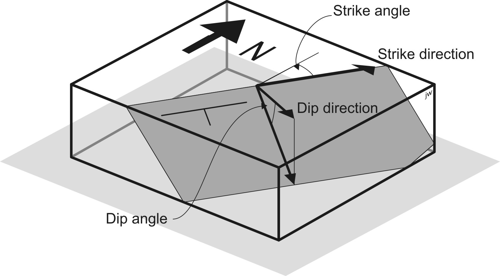
There are two directions in which we could measure the strike, 180° apart! The dip direction is clockwise from one, and counterclockwise from the other. In most Canadian geological field work, the right-hand rule (‘RHR‘) is used to avoid this ambiguity.
Right-hand rule: When you are facing in the strike direction, the plane dips downward to your right.
An equivalent statement is that strike is always 90° counter-clockwise from the dip direction.
It’s a good idea to add a rough compass direction to the dip measurement, just as a check that right-hand rule measurement has been done correctly. For example:
345/45 NE
specifies a plane that dips at 45° with strike roughly NNW. The dip direction is clockwise from the strike, so the dip direction is ENE – but ‘NE’ indicates that we have the direction right.
Other conventions for defining the orientation of a plane
Unfortunately, there are several other conventions to resolve strike ambiguity.
Some geologists prefer to record whichever strike direction is less than 180, and use letters (e.g. ‘NE’) to resolve the ambiguity. In this convention (‘strike, dip, alphabetic dip direction’) the above measurement would be written:
165/45 NE
Other geologists prefer to record dip direction and dip. In the ‘dip-direction, dip’ (DDD) convention, the above measurement would be written:
075,45
In the UK the strike has sometimes been specified so that the dip direction is counterclockwise from the strike, though confusingly this convention is also called ‘right-hand rule’. If you want to know the logic for this convention, ask a British geologist! (It has nothing to do with driving on the left side of the road.) In this convention, our plane would be:
165/45
In most work for this course, planes will be specified using the (Canadian) right-hand rule. However, you should be prepared, as geologists, to work with data collected using any of the other conventions.
Relationship of lines to planes
Often it’s possible to measure several different linear and planar structures at a single outcrop. Sometimes there are special relationships between these structures. The following sections describe some of these relationships.
Intersecting planes
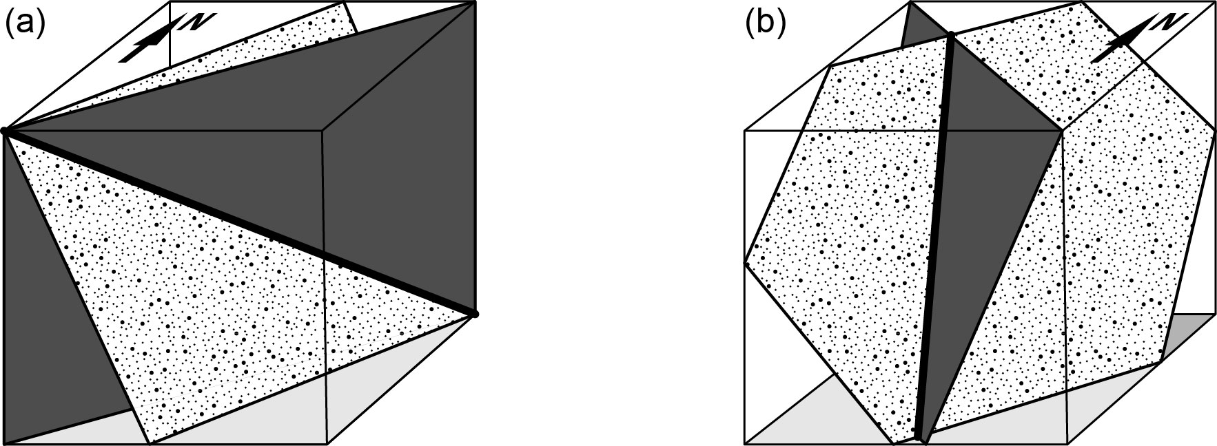
If two planar structures have different orientations, they will intersect in space. The intersection of two non-parallel planes defines a line (Fig 5). The orientation of the intersection line depends only on the orientation of the two planes. (If we change the position of one or both planes but keep their orientation constant, the location of the line of intersection will change, but not its orientation.) There are many situations that you will meet in this manual where planes intersect. The following are particularly important:
- The intersection of a geological surface with the topographic surface (the ground) is called the surface trace or outcrop trace (or just trace) of that surface. Geological maps are typically divided into areas of different colours (for different rock units) that are bounded by lines; these lines on the map are the traces of the geological surfaces that separate the units.
- The intersection of a fault plane with a planar rock unit that the fault displaces produces a line called the fault cut-off or cutoff.
- The two sides, or limbs, of a fold may intersect on a line called the fold hinge.
- The truncation, at an unconformity, of an older planar rock unit or surface by a younger one with a different orientation in space produces a line which may be called the subcrop, or subcrop limit.
Line that lies in a plane
On any given plane, it’s possible to draw an infinite number of lines that are parallel to, or ‘lie in‘, the plane. Some examples are current lineations that lie in bedding planes, and striations on fault planes that lie in the fault plane itself.
The orientation of a line that lies in a plane may be specified by rake or pitch. Unlike an azimuth (which is measured from north in a horizontal plane) or an inclination (which is measured from horizontal in a vertical plane) a rake is measured from horizontal in an inclined plane as shown in Fig. 6. As with strike, there are several conventions for specifying rake. We recommend measuring the rake of a line from the ‘right-hand rule’ strike direction, clockwise when looking down on the surface, as an angle between 000° and 180°.
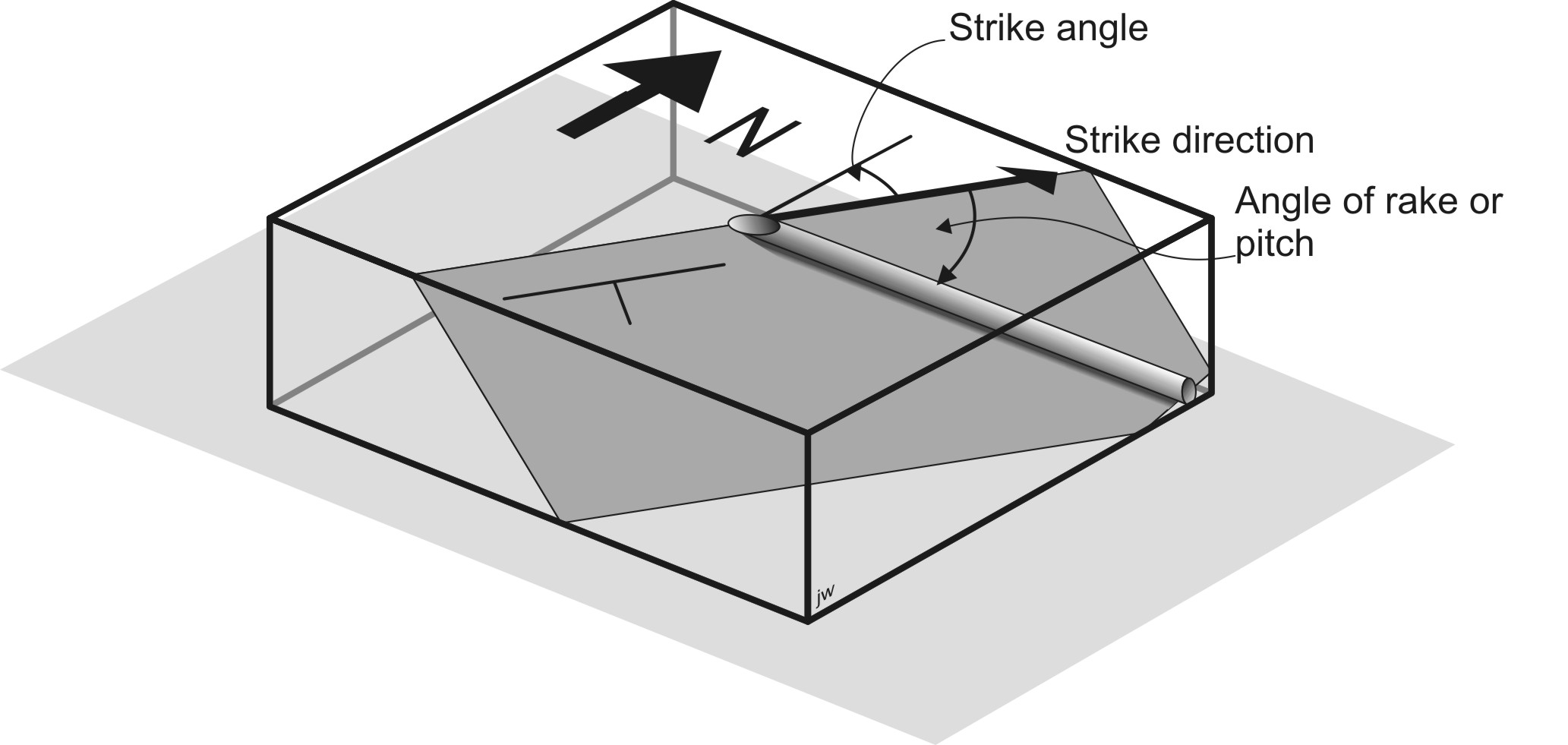
For example, a geologist may record a fault surface like this:
Fault plane 075/78 SE; Slickenlines rake 108°
On a vertical plane the rake of a line is the same as its plunge. On all other planes, rake ≥ plunge.
Remember:it only makes sense to measure a rake when a line lies in a plane.
Pole to a plane
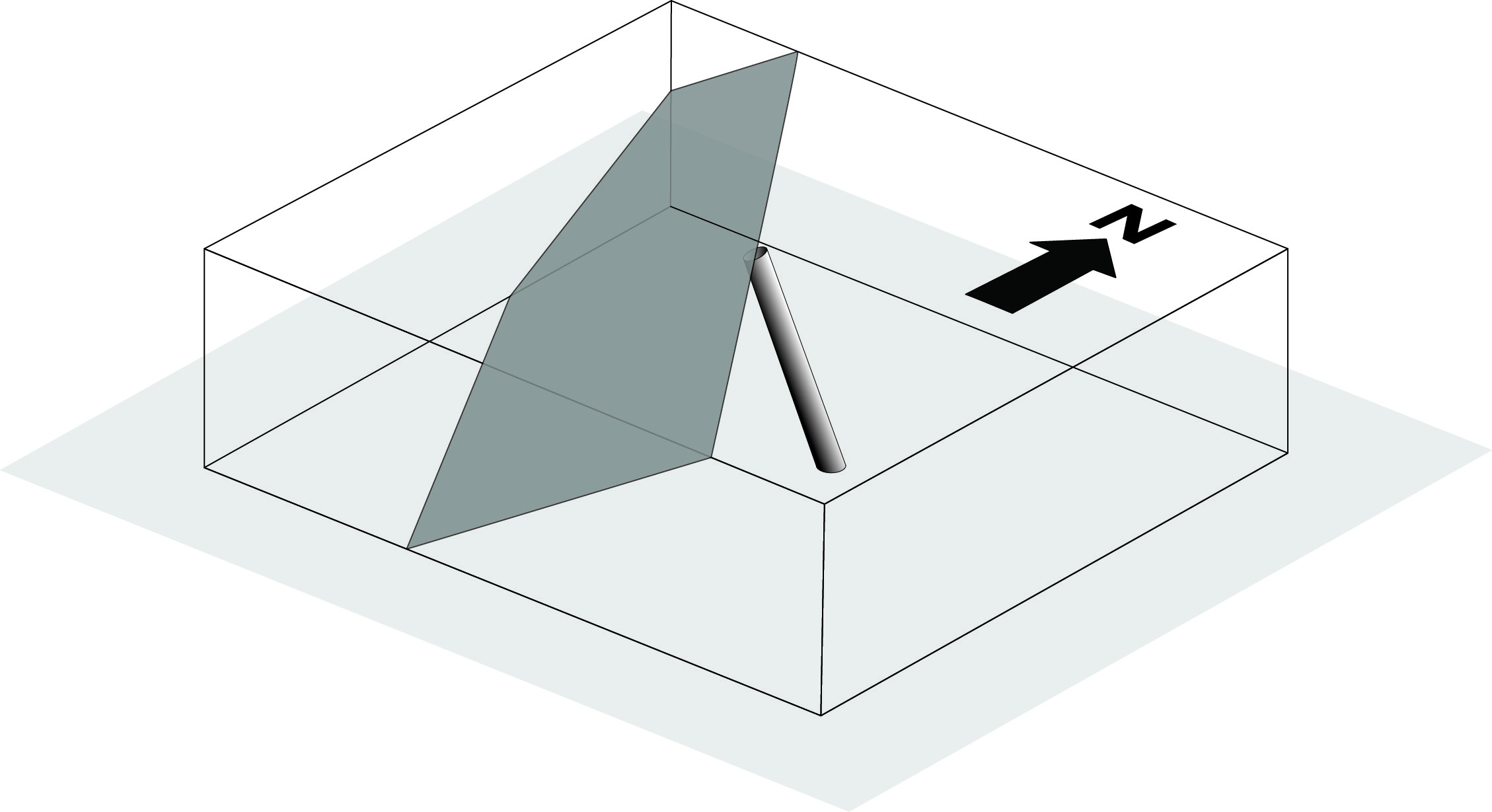
There’s also an infinite number of other lines are not parallel to any given plane (they may pierce the plane). One special line is perpendicular to any given plane: it’s sometimes called the pole to the plane. We will meet poles to planes in a later section of the course.
Contours
What are contours?
Contours are curving lines on a map that are widely used in the Earth sciences to show the variation of some quantity over the Earth’s surface. You are probably most familiar with topographic contours that show the shape of the land surface. However, Earth science uses many other types of contours such as:
- Magnetic contours: Variations in the strength of the Earth’s magnetic field;
- Isobars: Variations in air pressure;
- Isopachs: Variations in the thickness of a stratigraphic unit;
- Structure contours: Variations in the elevation above sea-level or depth below sea-level of a geological surface.
In each of these cases a numerical quantity, such as the elevation of a surface, varies from place to place, and the contour lines illustrate that spatial variation.
A contour is a curving line on a map that separates higher values of some quantity from lower values.
A contour can also be thought of as a line connecting points at which the measured quantity has constant value. Each contour line is labelled with this constant value; a map covered with contour lines is a useful expression of the spatial variation of the measured quantity.
(Note: This property is sometimes used as a definition of a contour. For example, a topographic contour is sometimes defined ‘as a line joining points of equal elevation‘. Although this is a satisfactory definition, it is harder to apply in practice, for two reasons. First, when the data are sparse, for example when working with drilled wells, it may be difficult to find any points of exactly equal elevation; locating such points requires interpolation. Second, it is very easy, when threading contours, to end up with “lower” points on both sides of the same contour line. This is always wrong! So, it is imperative when drawing a contour to remember that it has a ‘high’ side and a ‘low’ side, so that it always separates higher and lower values.)
Often, the measured quantity is the elevation of the Earth’s surface, above or below sea level. A topographic contour can be considered as a line on the ground separating points of higher and lower elevation. It can also be thought of as the line of intersection of the ground surface with a horizontal plane. Below sea level, contours showing the elevation of the sea floor are known as bathymetric contours.
On most topographic maps, topographic contours are separated by a constant interval: for example, contours on a map might be drawn at 310, 320, 330, 340 m etc. The spacing of the contours is called the contour interval. In this example the contour interval is 10 m.
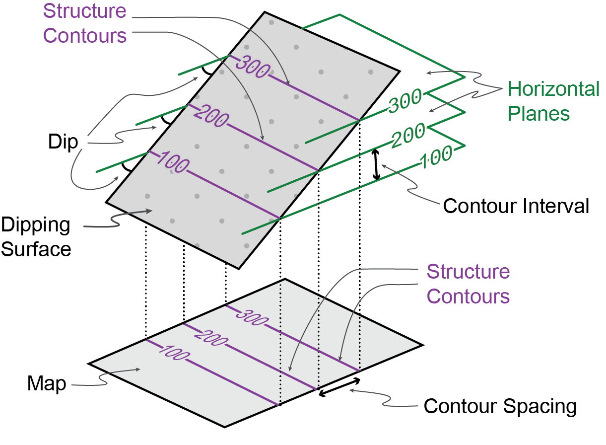
A structure contour (Fig. 8) is a contour line on a geologic surface, such as the top or bottom of a rock formation, a fault, or an unconformity. Typically, structure contours are drawn on surfaces that are buried underground. However, sometimes it’s possible to guess where a geologic surface was before it was eroded away; structure contours are then drawn for this imaginary surface above ground! Just like a topographic contour, a structure contour is the line of intersection of the contoured surface with a horizontal plane.
Strike, dip, and contours
Because structure contours are by definition lines of constant elevation, they are parallel to the strike of the geologic surface. They are sometimes called strike lines. So, given a pattern of structure contours it’s possible to determine the strike of the surface at any point.
The dip of the surface controls how far apart the contours are. Where a surface dips steeply, the contours are close together; where the surface is near-horizontal the contours are far apart. The horizontal spacing of contours, recorded on the map is called the contour spacing. There is a simple relationship between the dip δ of a surface and the spacing of its contours.
tan (δ) = contour interval / contour spacing
If a surface is planar (i.e. the strike and dip are constant) then the contours will be parallel, equally spaced, straight lines. Thus you can readily determine the orientation of a surface from the azimuth and spacing of its structure contours.
Contours and outcrop traces
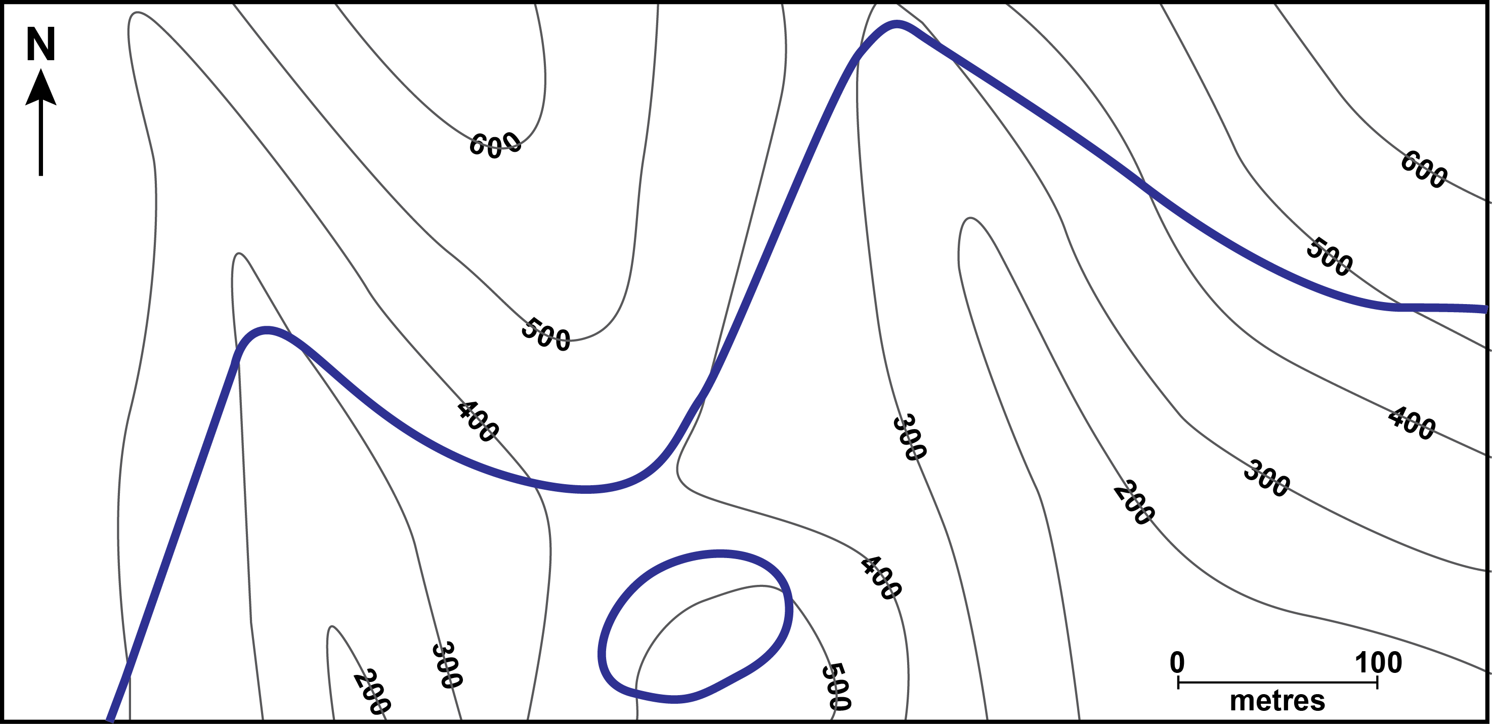
On a geologic map, a geologic surface such as the boundary between two map-units appears as a line, called the outcrop trace or topographic trace of that boundary (Fig. 9). Typically, the outcrop traces of geological units are quite complicated, curving lines, because they are affected both by the dip of the geologic surface and the complex shape of the topographic surface. Because of this, in areas of topographic relief, it’s often possible to use the outcrop trace of a boundary between two rock units to make inferences about the strike and dip of the units.
The precise orientation of a surface can be determined from its outcrop trace because its position and elevation are known at every point where the trace crosses a topographic contour line. These intersection points can be used for drawing structure contours (Fig. 10). Thus, for example, the 400 m structure contour is constructed by connecting all points where the outcrop trace crosses the 400 m topographic contour. Once a number of structure contours have been drawn, the orientation of the surface may be determined from the spacing and orientation of the structure contours.
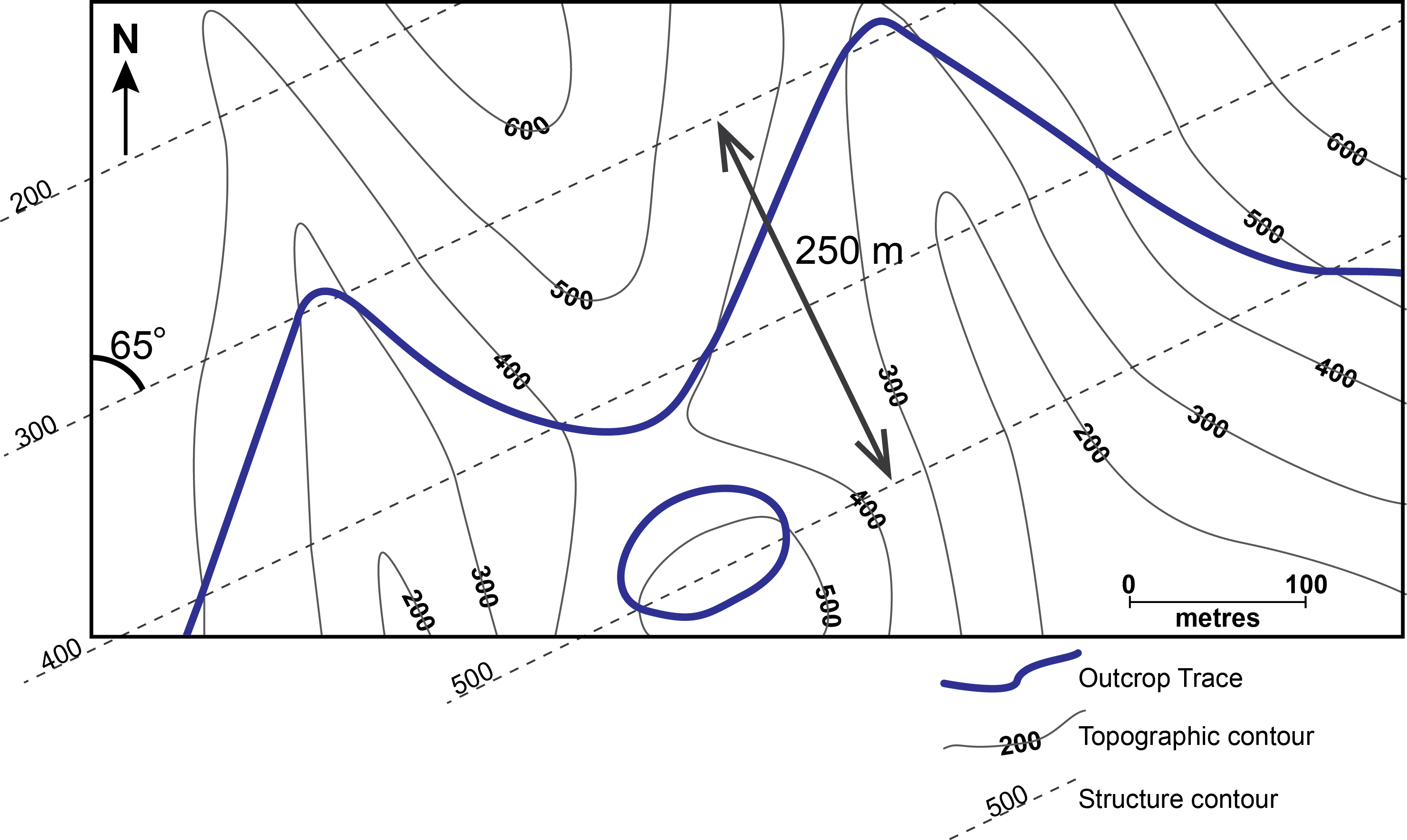
Conversely, if structure contours of a geologic surface are known, its trace can be determined by connecting points where the geologic and topographic surfaces have the same elevation; i.e. the trace connects points where structure and topographic contours with the same elevation cross one another.
Where the elevation of a structure contour is greater than topographic elevation, this means the geological surface is “above ground”, and has thus been removed by erosion at that location. Conversely, where the elevation of a structure contour is less than topographic elevation, this means the geological surface is below ground, or in the subsurface, and can be encountered by excavation or drilling. The outcrop trace of a geological surface can thus be thought of as a line that separates a region where that surface is present below ground, from another region where the surface has been eroded away above the present-day ground.
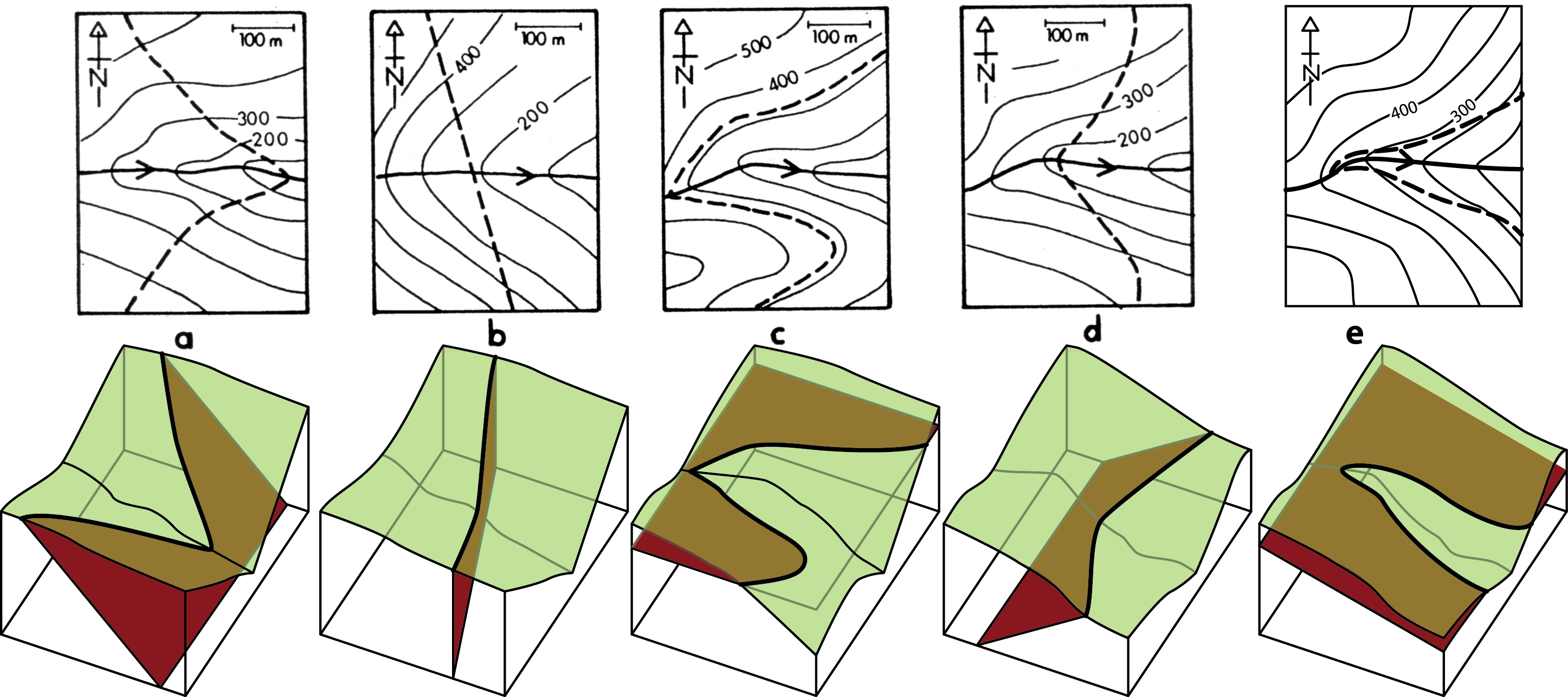
There are some general considerations when constructing geologic traces (Fig. 11).
- The outcrop trace of a horizontal geological surface is parallel to the topographic contours.
- The outcrop trace of a vertical geological surface is a straight line parallel to the strike; it ignores topographic contours.
- The outcrop traces of dipping surfaces show V-shapes as they cross valleys and ridges; these regions are particularly useful in determining strike and dip.
- In general, the V-shape formed as a trace crosses a river valley points in the direction of dip. (This is known as the “rule of vees”.) The only exception occurs when the dip is in the same direction as the slope of the valley, but gentler than the gradient of the river; then the V-shapes point up-dip.
- For planar surfaces with shallow dip (gentler than the typical hill slopes of topography in the region) the outcrop trace will generally follow topographic contours quite closely, crossing them at widely spaced intervals.
- In such regions, the relative position of a top or bottom contact of a unit can be inferred from the local topography. For example, if the position of the bottom trace of a unit is known then the top of the unit must be exposed at a higher elevation.
A geologic trace should never cross a topographic contour except where the identical structural and topographic contours intersect.


