8.3.1: Water Management Practices for Shale Energy Production
- Page ID
- 15676
\( \newcommand{\vecs}[1]{\overset { \scriptstyle \rightharpoonup} {\mathbf{#1}} } \)
\( \newcommand{\vecd}[1]{\overset{-\!-\!\rightharpoonup}{\vphantom{a}\smash {#1}}} \)
\( \newcommand{\id}{\mathrm{id}}\) \( \newcommand{\Span}{\mathrm{span}}\)
( \newcommand{\kernel}{\mathrm{null}\,}\) \( \newcommand{\range}{\mathrm{range}\,}\)
\( \newcommand{\RealPart}{\mathrm{Re}}\) \( \newcommand{\ImaginaryPart}{\mathrm{Im}}\)
\( \newcommand{\Argument}{\mathrm{Arg}}\) \( \newcommand{\norm}[1]{\| #1 \|}\)
\( \newcommand{\inner}[2]{\langle #1, #2 \rangle}\)
\( \newcommand{\Span}{\mathrm{span}}\)
\( \newcommand{\id}{\mathrm{id}}\)
\( \newcommand{\Span}{\mathrm{span}}\)
\( \newcommand{\kernel}{\mathrm{null}\,}\)
\( \newcommand{\range}{\mathrm{range}\,}\)
\( \newcommand{\RealPart}{\mathrm{Re}}\)
\( \newcommand{\ImaginaryPart}{\mathrm{Im}}\)
\( \newcommand{\Argument}{\mathrm{Arg}}\)
\( \newcommand{\norm}[1]{\| #1 \|}\)
\( \newcommand{\inner}[2]{\langle #1, #2 \rangle}\)
\( \newcommand{\Span}{\mathrm{span}}\) \( \newcommand{\AA}{\unicode[.8,0]{x212B}}\)
\( \newcommand{\vectorA}[1]{\vec{#1}} % arrow\)
\( \newcommand{\vectorAt}[1]{\vec{\text{#1}}} % arrow\)
\( \newcommand{\vectorB}[1]{\overset { \scriptstyle \rightharpoonup} {\mathbf{#1}} } \)
\( \newcommand{\vectorC}[1]{\textbf{#1}} \)
\( \newcommand{\vectorD}[1]{\overrightarrow{#1}} \)
\( \newcommand{\vectorDt}[1]{\overrightarrow{\text{#1}}} \)
\( \newcommand{\vectE}[1]{\overset{-\!-\!\rightharpoonup}{\vphantom{a}\smash{\mathbf {#1}}}} \)
\( \newcommand{\vecs}[1]{\overset { \scriptstyle \rightharpoonup} {\mathbf{#1}} } \)
\( \newcommand{\vecd}[1]{\overset{-\!-\!\rightharpoonup}{\vphantom{a}\smash {#1}}} \)
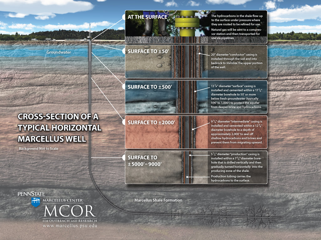
\(\newcommand{\avec}{\mathbf a}\) \(\newcommand{\bvec}{\mathbf b}\) \(\newcommand{\cvec}{\mathbf c}\) \(\newcommand{\dvec}{\mathbf d}\) \(\newcommand{\dtil}{\widetilde{\mathbf d}}\) \(\newcommand{\evec}{\mathbf e}\) \(\newcommand{\fvec}{\mathbf f}\) \(\newcommand{\nvec}{\mathbf n}\) \(\newcommand{\pvec}{\mathbf p}\) \(\newcommand{\qvec}{\mathbf q}\) \(\newcommand{\svec}{\mathbf s}\) \(\newcommand{\tvec}{\mathbf t}\) \(\newcommand{\uvec}{\mathbf u}\) \(\newcommand{\vvec}{\mathbf v}\) \(\newcommand{\wvec}{\mathbf w}\) \(\newcommand{\xvec}{\mathbf x}\) \(\newcommand{\yvec}{\mathbf y}\) \(\newcommand{\zvec}{\mathbf z}\) \(\newcommand{\rvec}{\mathbf r}\) \(\newcommand{\mvec}{\mathbf m}\) \(\newcommand{\zerovec}{\mathbf 0}\) \(\newcommand{\onevec}{\mathbf 1}\) \(\newcommand{\real}{\mathbb R}\) \(\newcommand{\twovec}[2]{\left[\begin{array}{r}#1 \\ #2 \end{array}\right]}\) \(\newcommand{\ctwovec}[2]{\left[\begin{array}{c}#1 \\ #2 \end{array}\right]}\) \(\newcommand{\threevec}[3]{\left[\begin{array}{r}#1 \\ #2 \\ #3 \end{array}\right]}\) \(\newcommand{\cthreevec}[3]{\left[\begin{array}{c}#1 \\ #2 \\ #3 \end{array}\right]}\) \(\newcommand{\fourvec}[4]{\left[\begin{array}{r}#1 \\ #2 \\ #3 \\ #4 \end{array}\right]}\) \(\newcommand{\cfourvec}[4]{\left[\begin{array}{c}#1 \\ #2 \\ #3 \\ #4 \end{array}\right]}\) \(\newcommand{\fivevec}[5]{\left[\begin{array}{r}#1 \\ #2 \\ #3 \\ #4 \\ #5 \\ \end{array}\right]}\) \(\newcommand{\cfivevec}[5]{\left[\begin{array}{c}#1 \\ #2 \\ #3 \\ #4 \\ #5 \\ \end{array}\right]}\) \(\newcommand{\mattwo}[4]{\left[\begin{array}{rr}#1 \amp #2 \\ #3 \amp #4 \\ \end{array}\right]}\) \(\newcommand{\laspan}[1]{\text{Span}\{#1\}}\) \(\newcommand{\bcal}{\cal B}\) \(\newcommand{\ccal}{\cal C}\) \(\newcommand{\scal}{\cal S}\) \(\newcommand{\wcal}{\cal W}\) \(\newcommand{\ecal}{\cal E}\) \(\newcommand{\coords}[2]{\left\{#1\right\}_{#2}}\) \(\newcommand{\gray}[1]{\color{gray}{#1}}\) \(\newcommand{\lgray}[1]{\color{lightgray}{#1}}\) \(\newcommand{\rank}{\operatorname{rank}}\) \(\newcommand{\row}{\text{Row}}\) \(\newcommand{\col}{\text{Col}}\) \(\renewcommand{\row}{\text{Row}}\) \(\newcommand{\nul}{\text{Nul}}\) \(\newcommand{\var}{\text{Var}}\) \(\newcommand{\corr}{\text{corr}}\) \(\newcommand{\len}[1]{\left|#1\right|}\) \(\newcommand{\bbar}{\overline{\bvec}}\) \(\newcommand{\bhat}{\widehat{\bvec}}\) \(\newcommand{\bperp}{\bvec^\perp}\) \(\newcommand{\xhat}{\widehat{\xvec}}\) \(\newcommand{\vhat}{\widehat{\vvec}}\) \(\newcommand{\uhat}{\widehat{\uvec}}\) \(\newcommand{\what}{\widehat{\wvec}}\) \(\newcommand{\Sighat}{\widehat{\Sigma}}\) \(\newcommand{\lt}{<}\) \(\newcommand{\gt}{>}\) \(\newcommand{\amp}{&}\) \(\definecolor{fillinmathshade}{gray}{0.9}\)The utilization of the abundant natural gas from shale formations is desirable as a cleaner-burning form of domestically-produced energy, however there are environmental challenges with its development, including water resource management. The graphic below shows the construction of a typical horizontal well illustrating that several strings of steel casing and cement are installed through the upper 1,000 or more feet of the earth to isolate and protect fresh groundwater zones from migrating methane or brine fluids. Once the well bore has reached the target zone in the shale, the horizontal section of the well is advanced several thousand feet in a direction that is favorable to open up fractures based on the Earth’s stress field. The approximate volume of water used during the well construction process is 100,000 gallons, primarily for drilling mud and cement.

Source: PSU Marcellus Center
Once the well drilling is complete, hydraulic fracturing is used to increase the permeability of the otherwise dense, tight shale to allow the hydrocarbons to be released from the shale and flow into the well. The hydraulic fracturing process involves injecting a mixture consisting of mostly water and sand along with a small proportion of other additives under high pressure through perforations in the steel casing that are connected to the surrounding shale to open up fractures. The volume of hydraulic fracturing fluids required for a horizontal well is typically about 4 to 5 million gallons, or about 1 to 1.5 million gallons per thousand feet of the well being fractured. The shale around the horizontal section of the well is fractured in sequential stages, consisting of sections each about 150-300 feet long, starting from the end of the well (known as the toe) and working back toward the bend in the well (known as the heel). A well with a 5,000 foot horizontal section may have 20 or more stages that are separately fractured, with each stage separated by special plugs to avoid loss of pressure into adjacent zones.
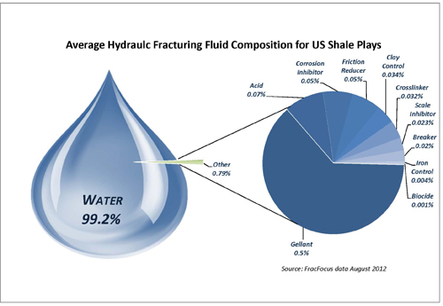
The typical chemicals added include a biocide solution to eliminate bacteria in the water, hydrochloric acid to clean up the well and fractures, a friction reducer to minimize fluid pressure losses down the well, a corrosion inhibitor to protect the steel casing, and a scale inhibitor to prevent precipitation in the well and surrounding formation as summarized in the graphic below. In order to keep the fractures open in the shale a proppant is added, typically sand, which can amount to 1-2 pounds of sand for every gallon of fluid used for fracturing operations. Most states experiencing significant shale energy production now require that the chemicals used in fracturing be publicly disclosed.

Source: Groundwater Protection Council
Exercise 4-1
Disclosure of additives used in hydraulic fracturing fluids is a regulatory requirement in many states using the FracFocus registry. Go to FracFocus and review the information on the website regarding how hydraulic fracturing works. Look up a well in your state or an area of interest to you. How much water did the well use for fracturing? How many different chemical additives were used to fracture the well? What percentage of the mixture was water, additives, and proppant?
The sources of water used for drilling and hydraulic fracturing are approved by state and/or river basin commission regulators and are withdrawn from surface waters (streams, rivers, ponds, lakes, reservoirs, etc), aquifers, purchased from municipal supplies, or may be sourced from municipal or industrial wastewater discharges. The amount of water that is permitted for withdrawal is typically quite small compared to the streams’ or aquifers’ available water to ensure that there are sufficient water resources for other uses as well as to sustain natural surface flow or groundwater levels.
Once the water is withdrawn, it is either piped or trucked to the well site for storage in steel tanks or a lined impoundment or as shown below. Modular above ground water storage facilities are becoming more prevalent as they can be erected in a short period of time (several days), and do not require as much earth-moving thus have a smaller surface footprint.
Once the necessary volume of water is transferred to the well site it is then withdrawn from the tanks or impoundment for use in the hydraulic fracturing process.
Exercise 4-2
A shale gas well has a horizontal section of 5,000 feet and would like to fracture the well in 20 stages, each 250 feet long. They plan to use 5,000,000 gallons of hydraulic fracturing fluid to stimulate gas production. How much water will be used per stage? How much water does this translate into for each foot of the well being fractured? The company plans to use 1.5 pounds of proppant per gallon of fluid. How much proppant will they use to fracture this well? How much proppant per foot will be used?
Once the hydraulic fracturing process is complete, the well can begins to produce hydrocarbons, but also will produce a significant volume of brine from the formation during the life of the well. The next section will address how these fluids are managed to avoid impacts to water quality.


