3.3: Topographic Maps
- Page ID
- 14270
\( \newcommand{\vecs}[1]{\overset { \scriptstyle \rightharpoonup} {\mathbf{#1}} } \)
\( \newcommand{\vecd}[1]{\overset{-\!-\!\rightharpoonup}{\vphantom{a}\smash {#1}}} \)
\( \newcommand{\id}{\mathrm{id}}\) \( \newcommand{\Span}{\mathrm{span}}\)
( \newcommand{\kernel}{\mathrm{null}\,}\) \( \newcommand{\range}{\mathrm{range}\,}\)
\( \newcommand{\RealPart}{\mathrm{Re}}\) \( \newcommand{\ImaginaryPart}{\mathrm{Im}}\)
\( \newcommand{\Argument}{\mathrm{Arg}}\) \( \newcommand{\norm}[1]{\| #1 \|}\)
\( \newcommand{\inner}[2]{\langle #1, #2 \rangle}\)
\( \newcommand{\Span}{\mathrm{span}}\)
\( \newcommand{\id}{\mathrm{id}}\)
\( \newcommand{\Span}{\mathrm{span}}\)
\( \newcommand{\kernel}{\mathrm{null}\,}\)
\( \newcommand{\range}{\mathrm{range}\,}\)
\( \newcommand{\RealPart}{\mathrm{Re}}\)
\( \newcommand{\ImaginaryPart}{\mathrm{Im}}\)
\( \newcommand{\Argument}{\mathrm{Arg}}\)
\( \newcommand{\norm}[1]{\| #1 \|}\)
\( \newcommand{\inner}[2]{\langle #1, #2 \rangle}\)
\( \newcommand{\Span}{\mathrm{span}}\) \( \newcommand{\AA}{\unicode[.8,0]{x212B}}\)
\( \newcommand{\vectorA}[1]{\vec{#1}} % arrow\)
\( \newcommand{\vectorAt}[1]{\vec{\text{#1}}} % arrow\)
\( \newcommand{\vectorB}[1]{\overset { \scriptstyle \rightharpoonup} {\mathbf{#1}} } \)
\( \newcommand{\vectorC}[1]{\textbf{#1}} \)
\( \newcommand{\vectorD}[1]{\overrightarrow{#1}} \)
\( \newcommand{\vectorDt}[1]{\overrightarrow{\text{#1}}} \)
\( \newcommand{\vectE}[1]{\overset{-\!-\!\rightharpoonup}{\vphantom{a}\smash{\mathbf {#1}}}} \)
\( \newcommand{\vecs}[1]{\overset { \scriptstyle \rightharpoonup} {\mathbf{#1}} } \)
\( \newcommand{\vecd}[1]{\overset{-\!-\!\rightharpoonup}{\vphantom{a}\smash {#1}}} \)
\(\newcommand{\avec}{\mathbf a}\) \(\newcommand{\bvec}{\mathbf b}\) \(\newcommand{\cvec}{\mathbf c}\) \(\newcommand{\dvec}{\mathbf d}\) \(\newcommand{\dtil}{\widetilde{\mathbf d}}\) \(\newcommand{\evec}{\mathbf e}\) \(\newcommand{\fvec}{\mathbf f}\) \(\newcommand{\nvec}{\mathbf n}\) \(\newcommand{\pvec}{\mathbf p}\) \(\newcommand{\qvec}{\mathbf q}\) \(\newcommand{\svec}{\mathbf s}\) \(\newcommand{\tvec}{\mathbf t}\) \(\newcommand{\uvec}{\mathbf u}\) \(\newcommand{\vvec}{\mathbf v}\) \(\newcommand{\wvec}{\mathbf w}\) \(\newcommand{\xvec}{\mathbf x}\) \(\newcommand{\yvec}{\mathbf y}\) \(\newcommand{\zvec}{\mathbf z}\) \(\newcommand{\rvec}{\mathbf r}\) \(\newcommand{\mvec}{\mathbf m}\) \(\newcommand{\zerovec}{\mathbf 0}\) \(\newcommand{\onevec}{\mathbf 1}\) \(\newcommand{\real}{\mathbb R}\) \(\newcommand{\twovec}[2]{\left[\begin{array}{r}#1 \\ #2 \end{array}\right]}\) \(\newcommand{\ctwovec}[2]{\left[\begin{array}{c}#1 \\ #2 \end{array}\right]}\) \(\newcommand{\threevec}[3]{\left[\begin{array}{r}#1 \\ #2 \\ #3 \end{array}\right]}\) \(\newcommand{\cthreevec}[3]{\left[\begin{array}{c}#1 \\ #2 \\ #3 \end{array}\right]}\) \(\newcommand{\fourvec}[4]{\left[\begin{array}{r}#1 \\ #2 \\ #3 \\ #4 \end{array}\right]}\) \(\newcommand{\cfourvec}[4]{\left[\begin{array}{c}#1 \\ #2 \\ #3 \\ #4 \end{array}\right]}\) \(\newcommand{\fivevec}[5]{\left[\begin{array}{r}#1 \\ #2 \\ #3 \\ #4 \\ #5 \\ \end{array}\right]}\) \(\newcommand{\cfivevec}[5]{\left[\begin{array}{c}#1 \\ #2 \\ #3 \\ #4 \\ #5 \\ \end{array}\right]}\) \(\newcommand{\mattwo}[4]{\left[\begin{array}{rr}#1 \amp #2 \\ #3 \amp #4 \\ \end{array}\right]}\) \(\newcommand{\laspan}[1]{\text{Span}\{#1\}}\) \(\newcommand{\bcal}{\cal B}\) \(\newcommand{\ccal}{\cal C}\) \(\newcommand{\scal}{\cal S}\) \(\newcommand{\wcal}{\cal W}\) \(\newcommand{\ecal}{\cal E}\) \(\newcommand{\coords}[2]{\left\{#1\right\}_{#2}}\) \(\newcommand{\gray}[1]{\color{gray}{#1}}\) \(\newcommand{\lgray}[1]{\color{lightgray}{#1}}\) \(\newcommand{\rank}{\operatorname{rank}}\) \(\newcommand{\row}{\text{Row}}\) \(\newcommand{\col}{\text{Col}}\) \(\renewcommand{\row}{\text{Row}}\) \(\newcommand{\nul}{\text{Nul}}\) \(\newcommand{\var}{\text{Var}}\) \(\newcommand{\corr}{\text{corr}}\) \(\newcommand{\len}[1]{\left|#1\right|}\) \(\newcommand{\bbar}{\overline{\bvec}}\) \(\newcommand{\bhat}{\widehat{\bvec}}\) \(\newcommand{\bperp}{\bvec^\perp}\) \(\newcommand{\xhat}{\widehat{\xvec}}\) \(\newcommand{\vhat}{\widehat{\vvec}}\) \(\newcommand{\uhat}{\widehat{\uvec}}\) \(\newcommand{\what}{\widehat{\wvec}}\) \(\newcommand{\Sighat}{\widehat{\Sigma}}\) \(\newcommand{\lt}{<}\) \(\newcommand{\gt}{>}\) \(\newcommand{\amp}{&}\) \(\definecolor{fillinmathshade}{gray}{0.9}\)Almost all of the area of the United States has been represented on topographic maps at various scales. For many years there were two standard map scales:
- Maps, called fifteen-minute quadrangle maps, that spanned 15' of longitude and 15' of latitude at a scale of 1:62,500, which is exactly one inch to the mile.
- Maps, called seven-and-a-half-minute quadrangle maps, that spanned 7-1/2' of longitude and 7-1/2' of latitude at a scale of 1:24,00.
In recent times those quadrangle maps have been supplanted by seven-and-a-half-minute quadrangle maps that are about the same size at the old 1:24,000 maps but at a slightly different, but more rational scale of 1:25,000. In addition, there is a series of maps with a scale of 1:250,000, called quarter-million maps. These latter, newer, maps use the metric system for map distances and contour intervals.
The 1:25,000 maps are what geologists typically use as a base for mapping the geology of a local area. The resulting maps are called geologic quadrangle maps. But often the detail of mapping that the geologist desires calls for a larger scale: that is, the map scale is such that a smaller land area is represented on a given sheet of paper. Detailed geologic maps are often at scales of between 1:10,000 and 1:5,000. The scale of map you work with depends on the level of detail you want to show on the map.
Topographic Contours
Many maps of land areas have series of curved lines, called contours, that represent the topography of the area. Such a map is called a topographic map. A contour is a horizontal curve that’s the locus of all points on the map with the same elevation (Figure 3-35). A good way to understand the concept of contours is to choose a series of elevations and imagine passing a corresponding series of horizontal planes through the landscape (Figure 3-36). The contours are formed by the intersection of these planes with the land surface.
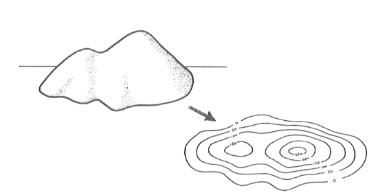
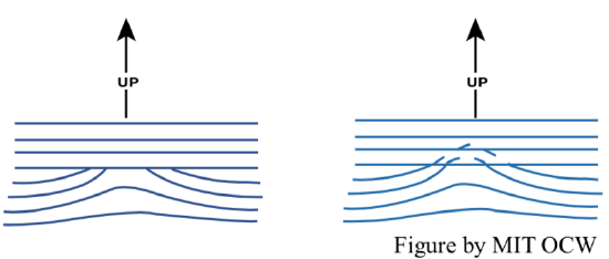
Adjacent contours touch one another only where the land surface is vertical, and they cross one another only where one part of the land surface hangs over another part (and in such overhanging areas, by convention the contours are dashed or dotted to indicate the overhanging relationship, or just omitted altogether).
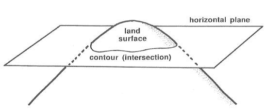
Topographic maps are useful to both technical people (geologists; environmental engineers) and to everyday people, like hikers. A geologist often uses a topographic map as a base on which to plot geology in making a geologic map.
Interpreting Contour Lines on Topographic Maps
To be a sophisticated user of a topographic map, you have to be able to visualize the topography or "lay of the land" by examining the contour lines. Or, even if you can’t do a good job of visualizing the topography, you at least have to understand how to interpret it from the contour lines. Here are some basic pointers. The best way to learn how to visualize topography from contour lines is to practice with a real map—and you will be doing that in the take-home exercise.
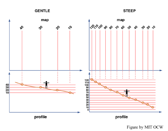
For a map at a given scale, the more closely spaced the contour lines, the steeper to slope of the surface: closely spaced contour lines mean steep slopes, and widely spaced contour lines mean gentle slopes (Figure 3-37).
You can easily compute the local slope of the land surface, by:
- measuring the distance between two points on the map,
- using the map scale to find the real distance on the land surface,
- finding the difference in elevation between the two points from the contour lines (at each point you usually have to interpolating between adjacent contour lines),
- forming a right triangle with one leg the horizontal distance and one leg the vertical distance, and
- finding the slope angle by trigonometry.
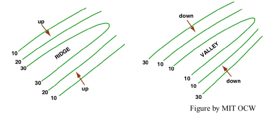
I suppose I need not insult your intelligence by pointing out (Figure 3-38) that hills or ridges are located where the contour lines on either side of the hill or ridge increase in elevation toward the top of the hill, and valleys are located where the contour lines on either side of the valley decrease in elevation toward the bottom of the valley.
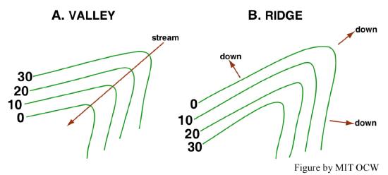
Valleys usually slope in one direction or another because they are occupied by streams, which, as you know, flow downhill. Such a valley shows up on the topographic map as a series of V-shaped kinks in the successive contour lines. Those “V”s point up the valley (Figure 3-39A). Conversely, ridges commonly have crests that slope downward in one direction or the other, and the contour lines in that case form “V”s that point down the ridge or spur (Figure 3-39B).
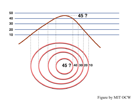
How do you know the elevation of a hilltop from a contour map? The answer is: you don’t, really, unless that information is supplied separately by being printed on the map! That’s because the tippity-top in general lies on the “incomplete” contour interval above the uppermost closed contour. But at least you can bracket the elevation of the summit to be within one contour interval (Figure 3-40).
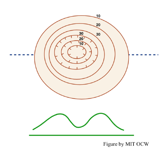
Closed depressions on the land surface are the opposite of hilltops, but in most areas they are uncommon or even nonexistent. Closed contours for which the elevation decreases inward are denoted in a special way, by putting little perpendicular tick marks on the downslope side of the closed contour (Figure 3-41).
Overhangs (also not common) are also treated in a special way: the obscured segments of contour lines are either ignored or drawn as dashed curves rather than as solid curves (Figure 3-42).
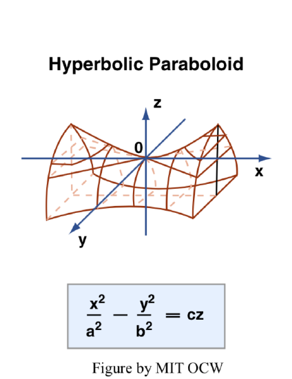
Now think in terms of riding saddles or curvy potato chips, or, for those mathematically inclined, hyperbolic paraboloids (Figure 3-11). In all of these cases, one is dealing with a curved surface such that the intersection between the surface and a vertical plane is convex up in one direction and concave up in a direction approximately at right angles to the first. Such features on topographic maps are called saddles or passes. Saddles are common along ridges where stream valleys indent the ridge from two opposite sides.
Locating Yourself on the Map
When you are working outdoors with a topographic map, the map is likely to be much more useful when you are able to locate where you are on the map. That’s a skill we won’t be able to practice in this course, unfortunately. Below are some considerations for you to keep in mind, in case you are called upon to work outdoors with a topographic map.
One way of locating yourself is simply to choose to be somewhere that corresponds to a readily identifiable feature on the map, like a road intersection, a stream confluence, or a mountaintop. But that’s overly restrictive: suppose you need to be somewhere not near such a feature?
One technique, which is useful in arid and semiarid regions with substantial relief (by relief I mean local differences in elevation from place to place) is to look back and forth from map to land, several times, to relate the topography shown on the map to the topography you can see on the ground. It’s a knack one acquires, usually readily and without much difficulty, by practice.
I have not been able to develop a laboratory exercise to make that technique real to students in a classroom, although for some years I have intended to put into practice an idea that might be useful in that regard. Perhaps one of you might be moved to pursue the idea. I would like to build a small table-top model of some small area with rugged mountain-and-valley topography by blowing up the topographic map of the area, cutting successive layers of a sheetlike material like the foam-core sheets used to mount prints, by tracing the outline of successive contour lines on successive sheets of the foam core, then stacking the sheets together, gluing them one by one, and covering the entire “terraced” mass with a moldable material like wallboard joint compound, and finally sanding the surface smooth. With such a model, one could do two instructive things:
- mark particular points on the model and ask students to locate the points on the map, and
- mark particular points on the map and ask students to show the corresponding location on the model.
It would be an extremely valuable teaching tool. If anyone, perhaps with some experience along that line, is interested in working on such a model, let me know.
The other technique, which is necessary in areas with low relief and/or heavy, view-obstructing vegetation, is surveying. You start from a known point on the map and run a survey line to the point of interest. This can be as crude as a compass-and-pace traverse or as sophisticated as a professional survey.
Visualizing the Lay of the Land
In working with topographic maps, one skill you need to develop is the ability to visualize the lay of the land from a topographic contour map. This involves picturing, in your mind’s eye, what the map area would really look like, in a view from a low-flying airplane on a clear day, just from the information provided by the topographic contours. To make full use of a topographic map, you need to be able to do that.
Visualizing topography from looking at the topographic contours on the map is a skill you have to develop for yourself, by thought and lots of practice. Some people can do it much more easily than others. It’s an exercise in using your “mind’s eye”, which is a useful skill in earth science, as well as in everyday life. (Think ahead toward when you might be wanting to remodel your home: can you picture the shape of your new kitchen, and how everything will fit together in it in three dimensions?)
To develop your skill in visualization, I will have a take-home exercise for you in which you will have to build a model of the earth’s surface, out of modeling clay, just by looking at a topographic map of the area.
Topographic Profiles
It is often useful to obtain a vertical cross-section view of the land surface along a line that extends from one point on the land to another point. It’s easy to construct such a profile if you have a topographic map of the area already available. Here’s how to proceed:
- Pinpoint the two points at the end of the desired profile directly on your topographic map, and draw a faint pencil line between them.
- Lay out, on a blank sheet of paper, a corresponding faint pencil line near the top of the paper than extends from the starting point on the land surface to the ending point. Establish a conversion ratio between the scale of the map and the scale of your cross-section line; then, as you pick points off the map, you can easily plot them along your cross-section line.
- For a large number of points along the profile line on the topographic map that happen to fall on topographic contour lines, pick off the elevations, and transfer them to your cross-section line on the sheet of paper.
- Connect the elevation points on your cross-section with a smooth curve.


