
7.4: Sedimentary Structures
- Page ID
- 11240

\( \newcommand{\vecs}[1]{\overset { \scriptstyle \rightharpoonup} {\mathbf{#1}} } \)
\( \newcommand{\vecd}[1]{\overset{-\!-\!\rightharpoonup}{\vphantom{a}\smash {#1}}} \)
\( \newcommand{\id}{\mathrm{id}}\) \( \newcommand{\Span}{\mathrm{span}}\)
( \newcommand{\kernel}{\mathrm{null}\,}\) \( \newcommand{\range}{\mathrm{range}\,}\)
\( \newcommand{\RealPart}{\mathrm{Re}}\) \( \newcommand{\ImaginaryPart}{\mathrm{Im}}\)
\( \newcommand{\Argument}{\mathrm{Arg}}\) \( \newcommand{\norm}[1]{\| #1 \|}\)
\( \newcommand{\inner}[2]{\langle #1, #2 \rangle}\)
\( \newcommand{\Span}{\mathrm{span}}\)
\( \newcommand{\id}{\mathrm{id}}\)
\( \newcommand{\Span}{\mathrm{span}}\)
\( \newcommand{\kernel}{\mathrm{null}\,}\)
\( \newcommand{\range}{\mathrm{range}\,}\)
\( \newcommand{\RealPart}{\mathrm{Re}}\)
\( \newcommand{\ImaginaryPart}{\mathrm{Im}}\)
\( \newcommand{\Argument}{\mathrm{Arg}}\)
\( \newcommand{\norm}[1]{\| #1 \|}\)
\( \newcommand{\inner}[2]{\langle #1, #2 \rangle}\)
\( \newcommand{\Span}{\mathrm{span}}\) \( \newcommand{\AA}{\unicode[.8,0]{x212B}}\)
\( \newcommand{\vectorA}[1]{\vec{#1}} % arrow\)
\( \newcommand{\vectorAt}[1]{\vec{\text{#1}}} % arrow\)
\( \newcommand{\vectorB}[1]{\overset { \scriptstyle \rightharpoonup} {\mathbf{#1}} } \)
\( \newcommand{\vectorC}[1]{\textbf{#1}} \)
\( \newcommand{\vectorD}[1]{\overrightarrow{#1}} \)
\( \newcommand{\vectorDt}[1]{\overrightarrow{\text{#1}}} \)
\( \newcommand{\vectE}[1]{\overset{-\!-\!\rightharpoonup}{\vphantom{a}\smash{\mathbf {#1}}}} \)
\( \newcommand{\vecs}[1]{\overset { \scriptstyle \rightharpoonup} {\mathbf{#1}} } \)
\( \newcommand{\vecd}[1]{\overset{-\!-\!\rightharpoonup}{\vphantom{a}\smash {#1}}} \)
\(\newcommand{\avec}{\mathbf a}\) \(\newcommand{\bvec}{\mathbf b}\) \(\newcommand{\cvec}{\mathbf c}\) \(\newcommand{\dvec}{\mathbf d}\) \(\newcommand{\dtil}{\widetilde{\mathbf d}}\) \(\newcommand{\evec}{\mathbf e}\) \(\newcommand{\fvec}{\mathbf f}\) \(\newcommand{\nvec}{\mathbf n}\) \(\newcommand{\pvec}{\mathbf p}\) \(\newcommand{\qvec}{\mathbf q}\) \(\newcommand{\svec}{\mathbf s}\) \(\newcommand{\tvec}{\mathbf t}\) \(\newcommand{\uvec}{\mathbf u}\) \(\newcommand{\vvec}{\mathbf v}\) \(\newcommand{\wvec}{\mathbf w}\) \(\newcommand{\xvec}{\mathbf x}\) \(\newcommand{\yvec}{\mathbf y}\) \(\newcommand{\zvec}{\mathbf z}\) \(\newcommand{\rvec}{\mathbf r}\) \(\newcommand{\mvec}{\mathbf m}\) \(\newcommand{\zerovec}{\mathbf 0}\) \(\newcommand{\onevec}{\mathbf 1}\) \(\newcommand{\real}{\mathbb R}\) \(\newcommand{\twovec}[2]{\left[\begin{array}{r}#1 \\ #2 \end{array}\right]}\) \(\newcommand{\ctwovec}[2]{\left[\begin{array}{c}#1 \\ #2 \end{array}\right]}\) \(\newcommand{\threevec}[3]{\left[\begin{array}{r}#1 \\ #2 \\ #3 \end{array}\right]}\) \(\newcommand{\cthreevec}[3]{\left[\begin{array}{c}#1 \\ #2 \\ #3 \end{array}\right]}\) \(\newcommand{\fourvec}[4]{\left[\begin{array}{r}#1 \\ #2 \\ #3 \\ #4 \end{array}\right]}\) \(\newcommand{\cfourvec}[4]{\left[\begin{array}{c}#1 \\ #2 \\ #3 \\ #4 \end{array}\right]}\) \(\newcommand{\fivevec}[5]{\left[\begin{array}{r}#1 \\ #2 \\ #3 \\ #4 \\ #5 \\ \end{array}\right]}\) \(\newcommand{\cfivevec}[5]{\left[\begin{array}{c}#1 \\ #2 \\ #3 \\ #4 \\ #5 \\ \end{array}\right]}\) \(\newcommand{\mattwo}[4]{\left[\begin{array}{rr}#1 \amp #2 \\ #3 \amp #4 \\ \end{array}\right]}\) \(\newcommand{\laspan}[1]{\text{Span}\{#1\}}\) \(\newcommand{\bcal}{\cal B}\) \(\newcommand{\ccal}{\cal C}\) \(\newcommand{\scal}{\cal S}\) \(\newcommand{\wcal}{\cal W}\) \(\newcommand{\ecal}{\cal E}\) \(\newcommand{\coords}[2]{\left\{#1\right\}_{#2}}\) \(\newcommand{\gray}[1]{\color{gray}{#1}}\) \(\newcommand{\lgray}[1]{\color{lightgray}{#1}}\) \(\newcommand{\rank}{\operatorname{rank}}\) \(\newcommand{\row}{\text{Row}}\) \(\newcommand{\col}{\text{Col}}\) \(\renewcommand{\row}{\text{Row}}\) \(\newcommand{\nul}{\text{Nul}}\) \(\newcommand{\var}{\text{Var}}\) \(\newcommand{\corr}{\text{corr}}\) \(\newcommand{\len}[1]{\left|#1\right|}\) \(\newcommand{\bbar}{\overline{\bvec}}\) \(\newcommand{\bhat}{\widehat{\bvec}}\) \(\newcommand{\bperp}{\bvec^\perp}\) \(\newcommand{\xhat}{\widehat{\xvec}}\) \(\newcommand{\vhat}{\widehat{\vvec}}\) \(\newcommand{\uhat}{\widehat{\uvec}}\) \(\newcommand{\what}{\widehat{\wvec}}\) \(\newcommand{\Sighat}{\widehat{\Sigma}}\) \(\newcommand{\lt}{<}\) \(\newcommand{\gt}{>}\) \(\newcommand{\amp}{&}\) \(\definecolor{fillinmathshade}{gray}{0.9}\)Sedimentary structures are visible textures or arrangements of sediments within a rock. Geologists use these structures to interpret the processes that made the rock and the environment in which it formed. They use uniformitarianism to usually compare sedimentary structures formed in modern environments to lithified counterparts in ancient rocks. Below is a summary discussion of common sedimentary structures that are useful for interpretations in the rock record.
Bedding Planes

The most basic sedimentary structure is bedding planes, the planes that separate the layers or strata in sedimentary and some volcanic rocks. Visible in exposed outcroppings, each bedding plane indicates a change in sediment deposition conditions. This change may be subtle. For example, if a section of underlying sediment firms up, this may be enough to create a form or a layer that is dissimilar from the overlying sediment. Each layer is called a bed, or stratum, the most basic unit of stratigraphy, the study of sedimentary layering.

As would be expected, bed thickness can indicate sediment deposition quantity and timing. Technically, a bed is a bedding plane thicker than 1 cm (0.4 in) and the smallest mappable unit. A layer thinner than 1 cm (0.4 in) is called a lamina [22]. Varves are bedding planes created when laminae and beds are deposited in repetitive cycles, typically daily or seasonally [23]. Varves are valuable geologic records of climatic histories, especially those found in lakes and glacial deposits.
Graded Bedding

Graded bedding refers to a sequence of increasingly coarse- or fine-grained sediment layers. Graded bedding often develops when sediment deposition occurs in an environment of decreasing energy. A Bouma sequence is graded bedding observed in a clastic rock called turbidite [24]. Bouma sequence beds are formed by offshore sediment gravity flows, which are underwater flows of sediment. These subsea density flows begin when sediment is stirred up by an energetic process and becomes a dense slurry of mixed grains. The sediment flow courses downward through submarine channels and canyons due to gravity acting on the density difference between the denser slurry and less dense surrounding seawater. As the flow reaches deeper ocean basins it slows down, loses energy, and deposits sediment in a Bouma sequence of coarse grains first, followed by increasingly finer grains (see figure).
Flow Regime and Bedforms
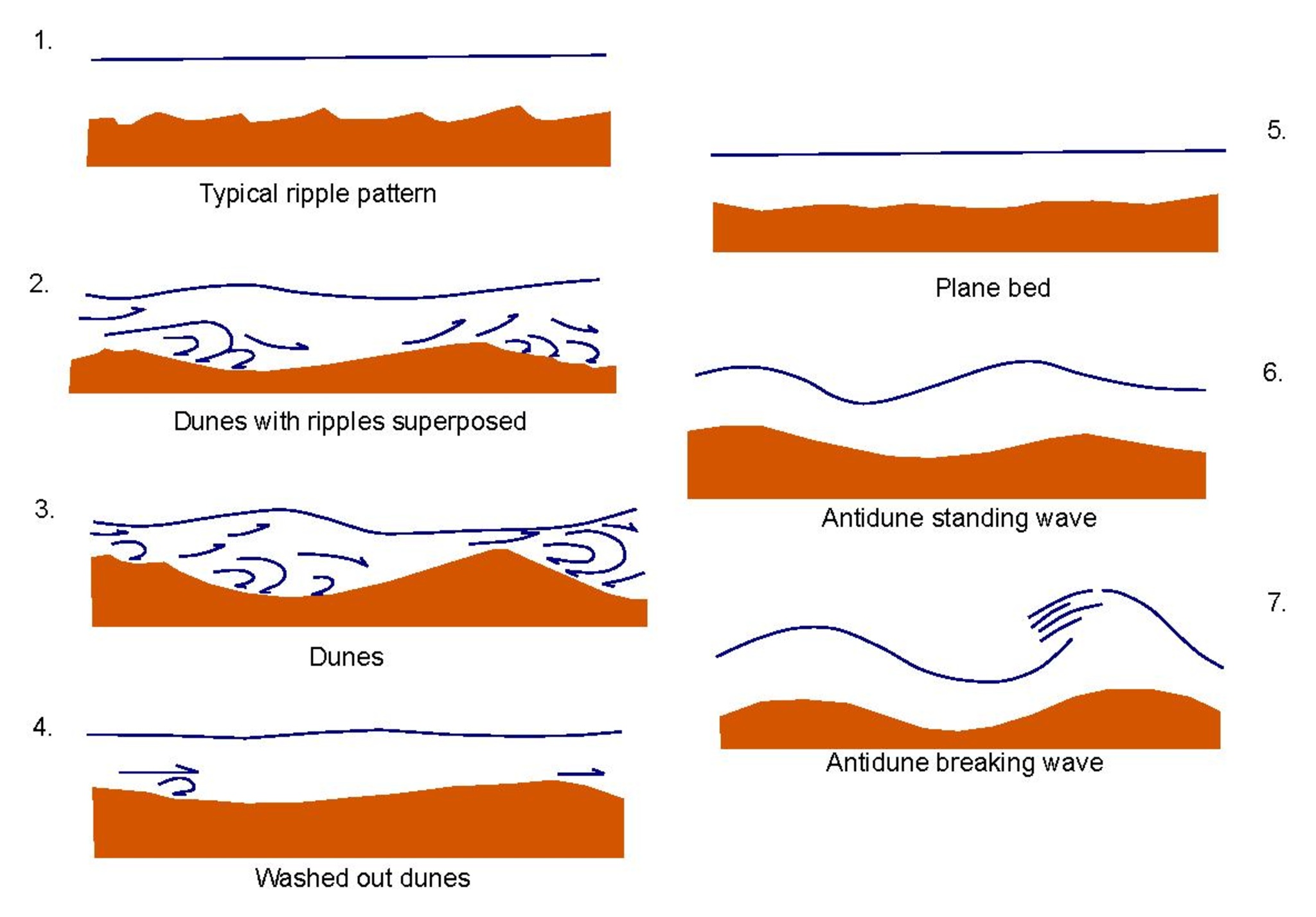
In fluid systems, such as moving water or wind, sand is the most easily transported and deposited sediment grain. Smaller particles like silt and clay are less movable by fluid systems because the tiny grains are chemically attracted to each other and stick to the underlying sediment. Under higher flow rates, the fine silt and clay sediment tend to stay in place and the larger sand grains get picked up and moved.
Bedforms are sedimentary structures created by fluid systems working on sandy sediment [25]. Grain size, flow velocity, and flow regime or pattern interact to produce bedforms having unique, identifiable physical characteristics. Flow regimes are divided into upper and lower regimes, which are further divided into uppermost, upper, lower, and lowermost parts. The table below shows bedforms and their associated flow regimes. For example, the dunes bedform is created in the upper part of the lower flow regime.
| Flow Regime (part) | Bedform | Description |
|---|---|---|
| Lower (lowest) | Plane bed | Lower plane bed, flat laminations |
| Lower (lower) | Ripples | Small (with respect to flow) inclined layers dipping downflow |
| Lower (upper) | Dunes | Larger inclined cross beds, ±ripples, dipping downflow |
| Upper (lower) | Plane bed | Flat layers, can include lined-up grains (parting lineations) |
| Upper (upper) | Antidunes | Hard to preserve reverse dunes dipping shallowly upflow |
| Upper (uppermost) | Chutes/pools (rare) | Erosional, not really a bedform; rarely found preserved |
Plane Beds

Plane beds created in the lower flow regime are like bedding planes, on a smaller scale. The flat, parallel layers form as sandy sediment piles and move on top of layers below. Even non-flowing fluid systems, such as lakes, can produce sediment plane beds. Plane beds in the upper flow regime are created by fast-flowing fluids. They may look identical to lower-flow-regime beds; however, they typically show parting lineations, slight alignments of grains in rows and swaths, caused by high sediment transport rates that only occur in upper flow regimes.
Ripples

Ripples are known by several names: ripple marks, ripple cross-beds, or ripple cross laminations. The ridges or undulations in the bed are created as sediment grains pile up on top of the plane bed. With the exception of dunes, the scale of these beds is typically measured in centimeters. Occasionally, large flows like glacial lake outbursts can produce ripples as tall as 20 m (66 ft).

First scientifically described by Hertha Ayrton [26], ripple shapes are determined by flow type and can be straight-crested, sinuous, or complex. Asymmetrical ripples form in a unidirectional flow. Symmetrical ripples are the result of an oscillating back-and-forth flow typical of intertidal swash zones. Climbing ripples are created from high sedimentation rates and appear as overlapping layers of ripple shapes (see figure).

Dunes

Dunes are very large and prominent versions of ripples and typical examples of large cross-bedding [27]. Cross bedding happens when ripples or dunes pile atop one another, interrupting, and/or cutting into the underlying layers. Desert sand dunes are probably the first image conjured up by this category of bedform.
British geologist Agnold (1941) considered only Barchan and linear Seif dunes as the only true dune forms. Other workers have recognized transverse and star dunes as well as parabolic and linear dunes anchored by plants that are common in coastal areas as other types of dunes.

Dunes are the most common sedimentary structure found within channelized flows of air or water. The biggest difference between river dunes and air-formed (desert) dunes is the depth of the fluid system. Since the atmosphere’s depth is immense when compared to a river channel, desert dunes are much taller than those found in rivers. Some famous air-formed dune landscapes include the Sahara Desert, Death Valley, and the Gobi Desert [28].
As airflow moves sediment along, the grains accumulate on the dune’s windward surface (facing the wind). The angle of the windward side is typically shallower than the leeward (downwind) side, which has grains falling down over it. This difference in slopes can be seen in a bed cross-section and indicates the direction of the flow in the past. There are typically two styles of dune beds: the more common trough cross-beds with curved windward surfaces, and rarer planar cross-beds with flat windward surfaces.
In tidal locations with strong in-and-out flows, dunes can develop in opposite directions. This produces a feature called herringbone cross-bedding.


Another dune formation variant occurs when very strong, hurricane-strength, winds agitate parts of the usually undisturbed seafloor. These beds are called hummocky cross-stratification and have a 3D architecture of hills and valleys, with inclined and declined layering that matches the dune shapes.
Antidunes

Antidunes are so named because they share similar characteristics with dunes, but are formed by a different, opposing process [29]. While dunes form in lower flow regimes, antidunes come from fast-flowing upper flow regimes. In certain conditions of high flow rates, the sediment accumulates upstream of a subtle dip instead of traveling downstream (see figure). Antidunes form in phase with the flow; in rivers, they are marked by rapids in the current. Antidunes are rarely preserved in the rock record because the high flow rates needed to produce the beds also accelerate erosion.
Bioturbation

Bioturbation is the result of organisms burrowing through soft sediment, which disrupts the bedding layers. These tunnels are backfilled and eventually preserved when the sediment becomes rock. Bioturbation happens most commonly in shallow, marine environments, and can be used to indicate water depth [30].
Mudcracks

Mudcracks occur in clay-rich sediment that is submerged underwater and later dries out. Water fills voids in the clay’s crystalline structure, causing the sediment grains to swell. When this waterlogged sediment begins to dry out, the clay grains shrink. The sediment layer forms deep polygonal cracks with tapered openings toward the surface [31], which can be seen in profile. The cracks fill with new sediment and become visible veins running through the lithified rock. These dried-out clay beds are a major source of mud chips, small fragments of mud or shale, which commonly become inclusions in sandstone and conglomerate. What makes this sedimentary structure so important to geologists is that they only form in certain depositional environments—such as tidal flats that form underwater and are later exposed to air. Syneresis cracks are similar in appearance to mud cracks but much rarer; they are formed when subaqueous (underwater) clay sediment shrinks [32].
Sole Marks

Sole marks are small features typically found in river deposits. They form at the base of a bed, the sole, and on top of the underlying bed. They can indicate several things about the deposition conditions, such as flow direction or stratigraphic up-direction (see Geopetal Structures section). Flute casts or scour marks are grooves carved out by the forces of fluid flow and sediment loads. The upstream part of the flow creates steep grooves and downstream the grooves are shallower. The grooves subsequently become filled by overlying sediment, creating a cast of the original hollow [33].

Formed similarly to flute casts but with a more regular and aligned shape, groove casts are produced by larger clasts or debris carried along in the water that scrape across the sediment layer. Tool marks come from objects like sticks carried in the fluid downstream or embossed into the sediment layer, leaving a depression that later fills with new sediment.

Load casts, an example of soft-sediment deformation, are small indentations made by an overlying layer of coarse sediment grains or clasts intruding into a softer, finer-grained sediment layer [34].
Raindrop Impressions

Like their name implies, raindrop impressions are small pits or bumps found in soft sediment. While they are generally believed to be created by rainfall, they may be caused by other agents such as escaping gas bubbles [35].
Imbrication

Imbrication is a stack of large and usually flat clasts—cobbles, gravels, mud chips, etc—that are aligned in the direction of fluid flow [36]. The clasts may be stacked in rows, with their edges dipping down and flat surfaces aligned to face the flow (see figure). Or their flat surfaces may be parallel to the layer and long axes aligned with the flow. Imbrications are useful for analyzing paleocurrents, or currents found in the geologic past, especially in alluvial deposits.
Geopetal Structures

Geopetal structures [37], also called up-direction indicators, are used to identify which way was up when the sedimentary rock layers were originally formed. This is especially important in places where the rock layers have been deformed, tilted, or overturned. Well-preserved mud cracks, sole marks, and raindrop impressions can be used to determine up direction. Other useful geopetal structures include:
- Vugs: Small voids in the rock that usually become filled during diagenesis. If the void is partially filled or filled in stages, it serves as a permanent record of a level bubble, frozen in time.
- Cross bedding – In places where ripples or dunes pile on top of one another, where one cross bed interrupts and/or cuts another below, this shows a cross-cutting relationship that indicates up direction.
- Ripples, dunes: Sometimes the ripples are preserved well enough to differentiate between the crests (top) and troughs (bottom).
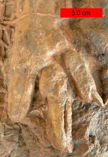
- Fossils: Body fossils in life position, meaning the body parts are not scattered or broken, and trace fossils like footprints (see figure) can provide an up direction. Intact fossilized coral reefs are excellent up indicators because of their large size and easily distinguishable top and bottom. Index fossils, such as ammonites, can be used to age date strata and determine up direction based on relative rock ages.
- Vesicles – Lava flows eliminate gas upwards. An increase of vesicles toward the top of the flow indicates up.
References
- 22. Mckee, E. D. & Weir, G. W. Terminology for stratification and cross-stratification in sedimentary rocks. Geol. Soc. Am. Bull. 64, 381–390 (1953).
- 23. de Geer, G. Geochronology of the last 12,000 years. in Milestones in Geosciences (eds. Dullo, P. D. W.-C. & e.V., G. V.) 100–110 (Springer Berlin Heidelberg, 2003).
- 24. Bouma, A. H., Kuenen, P. H. & Shepard, F. P. Sedimentology of some flysch deposits: a graphic approach to facies interpretation. 168, (Elsevier Amsterdam, 1962).
- 25. Blatt, H., Middleton, G. V. & Murray, R. Origin of Sedimentary Rocks. (Prentice-Hall, Inc., Englewood Cliffs, New Jersey, USA, 1980).
- 26. Ayrton, H. The origin and growth of ripple-mark. Proceedings of the Royal Society of London. Series A, Containing Papers of a Mathematical and Physical Character 84, 285–310 (1910).
- 27. Ashley, G. M. Classification of large-scale subaqueous bedforms: a new look at an old problem-SEPM bedforms and bedding structures. J. Sediment. Res. 60, (1990).
- 28. Dingus, L. & Loope, D. Death in the Dunes. Nat. Hist. 109, 50–55 (2000).
- 29. Gilbert, G. K. & Murphy, E. C. The Transportation of Débris by Running Water. (U.S. Government Printing Office, 1914).
- 30. Ekdale, A. A. Classification of Trace Fossils. (1984).
- 31. Plummer, P. S. & Gostin, V. A. Shrinkage cracks: desiccation or synaeresis? J. Sediment. Res. 51, (1981).
- 32. Burst, J. F. Subaqueously formed shrinkage cracks in clay. J. Sediment. Res. 35, (1965).
- 33. Yin, D. et al. Bedform genesis in bedrock substrates: Insights into formative processes from a new experimental approach and the importance of suspension-dominated abrasion. Geomorphology 255, 26–38 (2016).
- 34. Pettijohn, F. J. & Potter, P. E. Atlas and glossary of primary sedimentary structures. (2012).
- 35. Metz, R. Why not raindrop impressions? J. Sediment. Res. 51, (1981).
- 36. Karátson, D., Sztanó, O. & Telbisz, T. Preferred clast orientation in volcaniclastic mass-flow deposits: application of a new photo-statistical method. J. Sediment. Res. 72, 823–835 (2002).
- 37. Sander, B. Contributions to the study of depositional fabrics: rhythmically deposited Triassic limestones and dolomites. (American Association of Petroleum Geologists, 1951).