1.12: Tectonic Environments of Faulting
- Page ID
- 12521
\( \newcommand{\vecs}[1]{\overset { \scriptstyle \rightharpoonup} {\mathbf{#1}} } \)
\( \newcommand{\vecd}[1]{\overset{-\!-\!\rightharpoonup}{\vphantom{a}\smash {#1}}} \)
\( \newcommand{\id}{\mathrm{id}}\) \( \newcommand{\Span}{\mathrm{span}}\)
( \newcommand{\kernel}{\mathrm{null}\,}\) \( \newcommand{\range}{\mathrm{range}\,}\)
\( \newcommand{\RealPart}{\mathrm{Re}}\) \( \newcommand{\ImaginaryPart}{\mathrm{Im}}\)
\( \newcommand{\Argument}{\mathrm{Arg}}\) \( \newcommand{\norm}[1]{\| #1 \|}\)
\( \newcommand{\inner}[2]{\langle #1, #2 \rangle}\)
\( \newcommand{\Span}{\mathrm{span}}\)
\( \newcommand{\id}{\mathrm{id}}\)
\( \newcommand{\Span}{\mathrm{span}}\)
\( \newcommand{\kernel}{\mathrm{null}\,}\)
\( \newcommand{\range}{\mathrm{range}\,}\)
\( \newcommand{\RealPart}{\mathrm{Re}}\)
\( \newcommand{\ImaginaryPart}{\mathrm{Im}}\)
\( \newcommand{\Argument}{\mathrm{Arg}}\)
\( \newcommand{\norm}[1]{\| #1 \|}\)
\( \newcommand{\inner}[2]{\langle #1, #2 \rangle}\)
\( \newcommand{\Span}{\mathrm{span}}\) \( \newcommand{\AA}{\unicode[.8,0]{x212B}}\)
\( \newcommand{\vectorA}[1]{\vec{#1}} % arrow\)
\( \newcommand{\vectorAt}[1]{\vec{\text{#1}}} % arrow\)
\( \newcommand{\vectorB}[1]{\overset { \scriptstyle \rightharpoonup} {\mathbf{#1}} } \)
\( \newcommand{\vectorC}[1]{\textbf{#1}} \)
\( \newcommand{\vectorD}[1]{\overrightarrow{#1}} \)
\( \newcommand{\vectorDt}[1]{\overrightarrow{\text{#1}}} \)
\( \newcommand{\vectE}[1]{\overset{-\!-\!\rightharpoonup}{\vphantom{a}\smash{\mathbf {#1}}}} \)
\( \newcommand{\vecs}[1]{\overset { \scriptstyle \rightharpoonup} {\mathbf{#1}} } \)
\( \newcommand{\vecd}[1]{\overset{-\!-\!\rightharpoonup}{\vphantom{a}\smash {#1}}} \)
\(\newcommand{\avec}{\mathbf a}\) \(\newcommand{\bvec}{\mathbf b}\) \(\newcommand{\cvec}{\mathbf c}\) \(\newcommand{\dvec}{\mathbf d}\) \(\newcommand{\dtil}{\widetilde{\mathbf d}}\) \(\newcommand{\evec}{\mathbf e}\) \(\newcommand{\fvec}{\mathbf f}\) \(\newcommand{\nvec}{\mathbf n}\) \(\newcommand{\pvec}{\mathbf p}\) \(\newcommand{\qvec}{\mathbf q}\) \(\newcommand{\svec}{\mathbf s}\) \(\newcommand{\tvec}{\mathbf t}\) \(\newcommand{\uvec}{\mathbf u}\) \(\newcommand{\vvec}{\mathbf v}\) \(\newcommand{\wvec}{\mathbf w}\) \(\newcommand{\xvec}{\mathbf x}\) \(\newcommand{\yvec}{\mathbf y}\) \(\newcommand{\zvec}{\mathbf z}\) \(\newcommand{\rvec}{\mathbf r}\) \(\newcommand{\mvec}{\mathbf m}\) \(\newcommand{\zerovec}{\mathbf 0}\) \(\newcommand{\onevec}{\mathbf 1}\) \(\newcommand{\real}{\mathbb R}\) \(\newcommand{\twovec}[2]{\left[\begin{array}{r}#1 \\ #2 \end{array}\right]}\) \(\newcommand{\ctwovec}[2]{\left[\begin{array}{c}#1 \\ #2 \end{array}\right]}\) \(\newcommand{\threevec}[3]{\left[\begin{array}{r}#1 \\ #2 \\ #3 \end{array}\right]}\) \(\newcommand{\cthreevec}[3]{\left[\begin{array}{c}#1 \\ #2 \\ #3 \end{array}\right]}\) \(\newcommand{\fourvec}[4]{\left[\begin{array}{r}#1 \\ #2 \\ #3 \\ #4 \end{array}\right]}\) \(\newcommand{\cfourvec}[4]{\left[\begin{array}{c}#1 \\ #2 \\ #3 \\ #4 \end{array}\right]}\) \(\newcommand{\fivevec}[5]{\left[\begin{array}{r}#1 \\ #2 \\ #3 \\ #4 \\ #5 \\ \end{array}\right]}\) \(\newcommand{\cfivevec}[5]{\left[\begin{array}{c}#1 \\ #2 \\ #3 \\ #4 \\ #5 \\ \end{array}\right]}\) \(\newcommand{\mattwo}[4]{\left[\begin{array}{rr}#1 \amp #2 \\ #3 \amp #4 \\ \end{array}\right]}\) \(\newcommand{\laspan}[1]{\text{Span}\{#1\}}\) \(\newcommand{\bcal}{\cal B}\) \(\newcommand{\ccal}{\cal C}\) \(\newcommand{\scal}{\cal S}\) \(\newcommand{\wcal}{\cal W}\) \(\newcommand{\ecal}{\cal E}\) \(\newcommand{\coords}[2]{\left\{#1\right\}_{#2}}\) \(\newcommand{\gray}[1]{\color{gray}{#1}}\) \(\newcommand{\lgray}[1]{\color{lightgray}{#1}}\) \(\newcommand{\rank}{\operatorname{rank}}\) \(\newcommand{\row}{\text{Row}}\) \(\newcommand{\col}{\text{Col}}\) \(\renewcommand{\row}{\text{Row}}\) \(\newcommand{\nul}{\text{Nul}}\) \(\newcommand{\var}{\text{Var}}\) \(\newcommand{\corr}{\text{corr}}\) \(\newcommand{\len}[1]{\left|#1\right|}\) \(\newcommand{\bbar}{\overline{\bvec}}\) \(\newcommand{\bhat}{\widehat{\bvec}}\) \(\newcommand{\bperp}{\bvec^\perp}\) \(\newcommand{\xhat}{\widehat{\xvec}}\) \(\newcommand{\vhat}{\widehat{\vvec}}\) \(\newcommand{\uhat}{\widehat{\uvec}}\) \(\newcommand{\what}{\widehat{\wvec}}\) \(\newcommand{\Sighat}{\widehat{\Sigma}}\) \(\newcommand{\lt}{<}\) \(\newcommand{\gt}{>}\) \(\newcommand{\amp}{&}\) \(\definecolor{fillinmathshade}{gray}{0.9}\)
Dynamics of faulting
Unlike ductile structures, the formation of fractures can be simulated experimentally using real rock samples subjected to stresses in presses. Figure 1 shows the common relationship between shear fractures and stress. Such fractures are known as conjugate shear fractures. Conjugate shear fractures provide one of the few circumstances where structural geologists can make confident dynamic interpretations based on simple field evidence.
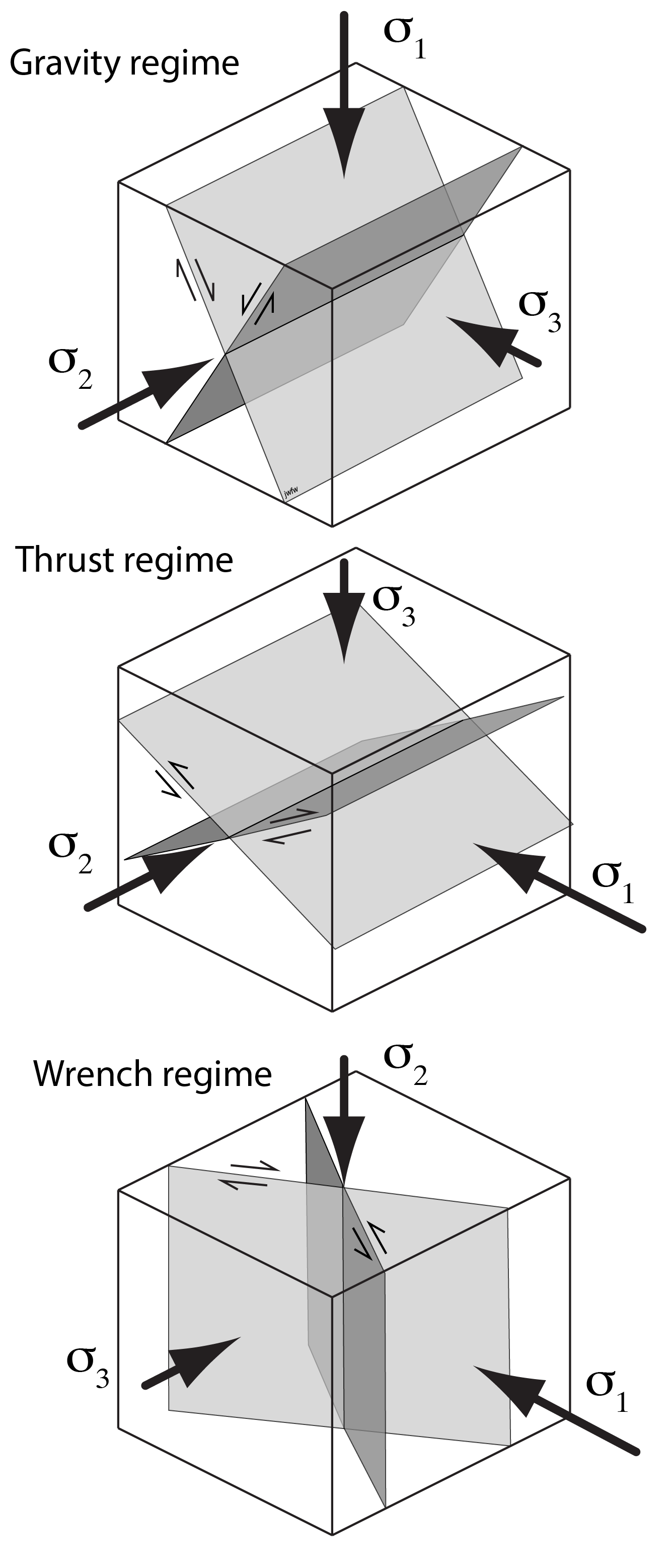
Anderson’s (1905) theory of faulting starts from some basic facts about stress, and leads to a classification of tectonic environments into fault regimes. Anderson noted that the Earth’s surface is effectively a plane of zero shear stress – at least as far as structural geologists are concerned. (We can neglect the relatively tiny shear stresses due to the wind and the flow of water.) This means that the Earth’s surface closely approximates a principal plane of stress, and the pole, or normal, to the Earth’s surface must be one of the principal stresses. Because the Earth’s surface is regionally close to horizontal, this means that over large areas of the Earth’s surface, one of the principal stresses is vertical, and the other two are horizontal.
Note that this argument strictly applies only at the Earth’s surface. Once we descend to lower levels in the lithosphere, the principal stresses can, and do, wander away from their vertical and horizontal orientations.
Based on which principal stress is near-vertical we can classify environments in the Earth’s upper crust into the following three categories.
Gravity régime: σ1 vertical: structure dominated by normal faults.
Thrust régime: σ3 vertical: structure dominated by thrust faults.
Wrench régime: σ2 vertical: structure dominated by strike-slip faults.
Rifts and extensional zones: normal faults
Occurrence
Several parts of the Earth’s crust are undergoing horizontal extension and crustal thinning at the present day. The best studied examples are probably the Basin and Range province of the western USA, and the East African Rift valley, which extends several thousand kilometres through Africa.
We can find ancient examples too. They are particularly well studied underneath passive continental margins, continental margins which are currently not located at a plate boundary. Passive margins mostly evolved from rift valleys similar to the East African Rift, as continents stretched and separated in the past. For this reason we find rift structures buried beneath passive continental margins in many parts of the world. Many of these contain significant petroleum reservoirs. The Hibernia structure on Canada’s east coast, formed in a rift that developed as the Atlantic opened. Many of the oilfields in the European North Sea occupy structures related to the Viking-Central Graben, buried beneath younger sedimentary rocks in the North Sea.
Features of normal faults in rifts
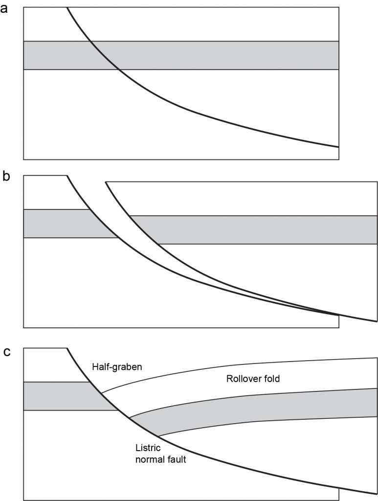
These regions are dominated by normal faults, and in many rifts they have a roughly conjugate geometry: faults dipping towards and away from each other with dips around 60°, at least near the surface. In many cases faults can be shown to flatten at depth, giving them listric geometry, though in some cases this is controversial. Some cross-sections of rifts show faults dipping at a constant angle down to a subhorizontal shear zone in the brittle crust at depth.

Listric shape has consequences for the geometry of the walls of faults: one or both walls must distort to maintain strain compatibility. Typically, the hanging wall distorts more (because it has a free surface at the top), and displays a characteristic type of fault-bend fold called a rollover anticline. Rollover anticlines form important petroleum traps in many passive continental margins.
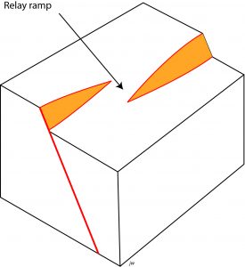
Other factors may lead to folding of the wall rocks. It is common in sedimentary basins for slip to vary across the surface of a fault, so that slip declines at the edges of a mapped fault, to a point where there is no slip at all, called the tip of the fault. How is this accommodated in the wall rocks? Typically, slip is transferred to another fault, but if the two faults are not connected, distortion of the wall rocks may produce a relay ramp linking the two.

Arrays of normal faults
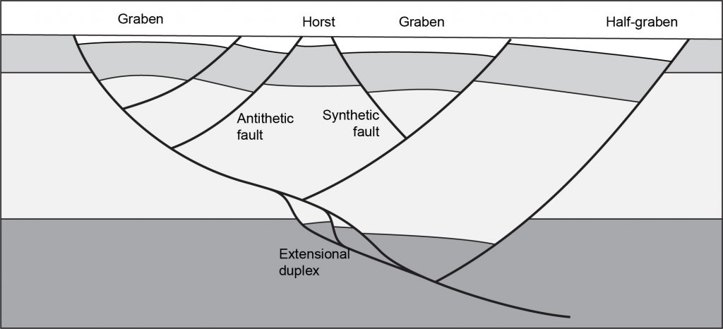
Normal faults in rifts do not occur in isolation. Often a cross-section through a rift will show dozens or hundreds of normal faults. Special terms are given to features of normal fault arrays.

A horst is a block between two normal faults that dip away from each other, in opposite directions. The rocks in a horst stand higher than the rocks on either side.
A graben is a block between two normal faults that dip towards each other. The rocks in a graben stand lower than the rocks on either side.
A half-graben is a tilted block in a rift zone, that is also dropped down relative to the rocks on either side, but it only has a fault on one side; the other side is typically gently folded.
In many rifts there are a few dominant normal faults with very large offsets. Faults that dip in the same direction are described as synthetic to the main faults; faults that dip in the opposite direction are antithetic.
Thrust belts
Occurrence
Areas of crustal shortening, dominated by reverse faults, are active at the present day at convergent plate boundaries (subduction zones), and in areas of continental collision: such as the Himalayas, and Taiwan.
Ancient examples occur in the Rocky Mountains formed in the late Mesozoic and early Cenozoic eras, and the Appalachian Mountains of eastern North America, formed in the Paleozoic era.
In most of these examples folds are intimately associated with thrusts.
In many cases, there is a sedimentary basin, called a foreland basin, adjacent to the thrust belt, and it is thought that the weight of the thrust belt has depressed the lithosphere as it formed by isostasy. In western Canada, most of the Cretaceous rocks formed in such a basin, including those that we see in the river valley in Edmonton.
Features of single thrust faults
Geometry: A thrust is any low-angle reverse fault, where low-angle is rather loosely defined. In fact, some thrust faults are sufficiently curved so that portions would technically be normal faults!
Because of their low angle character, thrusts may look like stratigraphic contacts on maps. There may be closed outlines of thrusts at hills and valleys.
- An area of hanging wall entirely surrounded by footwall is called a klippe.
- An area of footwall entirely surrounded by hanging wall is called a fenster or tectonic window.
Thrusts are influenced by stratigraphy. In many instances, the dip is steeper in competent rocks like limestone and sandstone, and shallower in incompetent rocks like shale and evaporites (rock salt, gypsum, anhydrite).

The steeper portions are ramps. They can be recognized on maps and cross-sections because the fault cuts stratigraphic boundaries at a relatively high angle. On ramps we can find cutoff points. Understanding the kinematics of a thrust belt often involves matching footwall and hanging wall cutoffs on the same fault. This process is an important part of checking cross-sections through thrust belts, known as section balancing.
The gentler portions are flats. They can be recognized on maps and cross-sections because the fault surfaces are almost parallel to the stratigraphic boundaries.
Notice that once a fault has moved, there will be separation between the hanging wallramps and the footwall ramps, and between the hanging wall flats and the footwall flats. If fault-bend folding occurs, then the hanging wall flats may acquire steeper dip and the hanging wall ramps may flatten, so this terminology may seem strange! They can still be recognized by the characteristic cutoff anglesof the strata.
A very extensive flat, where there has been a large amount of movement, is called a décollement surface, from a French word meaning ‘unstick’. If the hanging wall has moved a long way relative to the footwall (tens of kilometres or more), far enough that the hanging wall rocks were formed in a completely different environment from the footwall, then the hanging wall is described as an allochthon (from two Greek words, meaning “other place”) and is said to be allochthonous. The footwall of such a thrust is called the autochthon, and is said to be authochtonous.
For example, in Newfoundland there is a complex of thrust sheets known as the Humber Arm Allochthon that is composed of Cambrian and Ordovician deep-water sedimentary rocks and ophiolites from the floor of the Iapetus Ocean. It was thrust on top of sedimentary rocks of more or less the same age range that were formed on a continental shelf, and therefore represent a very different environment.
Folds associated with thrust faults
Folds may form in association with thrust faults. A wide variety of fold styles are recognized but we will recognize just three types:
Fault-bend folds: formed where the dip of the fault changes;
Detachment folds: formed where the slip changes, and distortion is accommodated in the hanging wall;
Fault-propagation folds: formed where the dip and the slip change, typically where a fault tip climbs up a ramp during fault-propagation.
In reality there are many variations on these themes. In particular, there is probably a continuous variation between the idealized detachment and fault propagation folds.
Arrays of thrust faults
Vergence is a useful concept in dealing with arrays of thrusts. The vergence of a structure is the direction in which rocks near the surface have moved relative to rocks deeper down. In some thrust arrays, all the thrusts have the same vergence: that is to say the hanging walls have all been displaced the same way relative to the footwall. Large parts of the Rocky Mountain thrust belt show eastward vergence, for example. The foreland is the area towards which most of the thrusts verge: in the Rockies, that is the plains of Alberta. The opposite side of the thrust belt, the side from which most of the thrust sheets appear to come, is called the hinterland.

Thrust arrays with similar vergence
Once we start looking at multiple thrusts things can get quite complicated. It is common for multiple listric thrust faults to branch upward from a single flat. This configuration is called an imbricate fan. The point where one thrust fault branches from another is called a branch point. In an imbricate fan the branch points mark places where one fault branches into two as you follow it towards the foreland. This type of branch point is a trailing branch point.
Sometimes imbricate thrust faults merge into flats both upward and downward. Such a configuration is called a duplex. The upper flat is a roof thrust while the lower flat is the floor thrust of the duplex. Like an imbricate fan, the thrusts in a duplex join downwards at trailing branch points. However, they also join upwards at leading branch points.
Thrusts with opposing vergence: wedges and triangle zones
Sometimes faults in thrust belts have opposing vergence. A pair of opposed thrusts that meet in the subsurface is called a tectonic wedge. If a third thrust cuts off a triangular section of rock, the wedge is called a triangle zone. The earliest oil discoveries in the foothills of the Canadian Rockies were found in a triangle zone in the Turner Valley area of southern Alberta.
Strike-slip zones
Occurrence
Some of the Earth’s best-known faults are strike-slip faults: the San Andreas in California is one of the best-known and best studied. Other strike-slip faults that have histories of damaging earthquakes include the North Anatolian Fault in Turkey and the Alpine Fault in New Zealand. Strike-slip faults that are also plate boundaries are called transform faults.
Characteristics of strike-slip faults and fault zones
Anderson’s theory of faulting predicts that strike-slip faults should be characteristic of the wrench regime, and that those faults should be near-vertical. Most major strike-slip faults are found to dip steeply, confirming Anderson’s prediction. As a result, their traces tend to be very straight lines on geological maps.

The damage zones around strike-slip faults tend to contain a mixture of structures that we normally associate either with horizontal shortening (as in thrust belts) or with horizontal extension (as in rifts). Cross-sections through strike slip faults tend to be quite confusing, for this reason. The best way to show what’s going on in a strike-slip zone is in map view.
In map view, a strike-slip fault zone may be idealized as a zone of simple shear. For the sake of argument we will draw a dextral strike-slip zone. (For a sinistral strike-slip zone everything would be in mirror image.) In a dextral strike-slip a zone, it’s possible to show that the most rapid shortening takes place along a line 45° clockwise from the shear-zone boundary, and the most rapid extension takes place along a line 45° counter-clockwise from the shear-zone boundary. For a sinistral strike-slip zone, the opposite senses of rotation apply.
This idealized pattern of strain rates leads to some predictions of how structures will form. We predict that extensional structures like joints, veins, and normal faults, will form perpendicular to the extension direction, and shortening structures like folds, thrust faults, and cleavage planes will develop perpendicular to the shortening direction.
It is also quite common to see subsidiary strike-slip faults, which may include Riedel shears. Dextral synthetic Riedel shears would be predicted at about 15° clockwise from our overall dextral strike-slip zone, while sinistral antithetic Riedel shears would be about 75° clockwise from the overall direction of dextral strike slip. (Reverse everything for a sinistral zone.)
All these orientations work for fault zones where the overall amount of strain is small. Strike-slip deformation includes a strong component of rotation, so as deformation continues, all the structures will be rotated. One of the challenges in interpreting strike-slip motion is that structures may have rotated out of the orientations in which they formed.
Transtension
The above predictions apply to ideal strike-slip motion. However, many of the most interesting structures in strike-slip zones are formed where there are departures from ideal strike-slip.
For example, a combination of strike-slip motion with extension is called transtension. In transtension there is a component of crustal thinning, along with strike slip, so transtension zones tend to subside and form sedimentary basins.
One common environment of transtension is at a releasing bend (also known as a releasing stepover) on a strike-slip fault. If a dextral fault steps to the right, or a sinistral fault steps to the left, the resulting bend is said to be releasing, and the rocks adjacent to the fault are affected by transtension.
A releasing bend typically develops a localized, parallelogram-shaped subsiding area called a pull-apart basin. In the Los Angeles area, pull-apart basins associated with the San Andreas system host important natural resources of oil and natural gas. In Nova Scotia, the Stellarton Basin, also a pull-apart basin on a dextral strike-slip fault system, was a prolific producer of coal in the 20th century.
In cross-section, pull-apart basins tend to be bounded by families of faults that steepen downwards and merge into a single fault or shear zone at depth. Individual faults may have normal, strike slip, or oblique slip. This type of fault array is called a negative flower structure.

Transpression
A combination of strike-slip motion with shortening is called transpression. In transpression there is a component of crustal thickening, along with strike slip, so transpression zones tend to form narrow uplifts, ranges of hills or mountains.
One common environment of transpression is at a restraining bend (also known as a restraining stepover) on a strike-slip fault. If a dextral fault steps to the left, or a sinistral fault steps to the right, the resulting bend is said to be restraining, and the rocks adjacent to the fault are affected by transpression.
A restraining bend typically develops a localized uplift. Parts of the transverse ranges of California, and the Southern Alps of New Zealand, are associated with transpression at restraining bends along major transform faults.
In cross-section, transpressional ranges tend to be bounded by families of faults that steepen downwards and merge into a single fault or shear zone at depth. Individual faults may have reverse, strike slip, or oblique slip. This type of fault array is called a positive flower structure.
Anderson, E. W. 1905. The dynamics of faulting. Transactions of the Edinburgh Geological Society8, 387-402.


