
9.6: Bedforms
- Page ID
- 10737

\( \newcommand{\vecs}[1]{\overset { \scriptstyle \rightharpoonup} {\mathbf{#1}} } \)
\( \newcommand{\vecd}[1]{\overset{-\!-\!\rightharpoonup}{\vphantom{a}\smash {#1}}} \)
\( \newcommand{\id}{\mathrm{id}}\) \( \newcommand{\Span}{\mathrm{span}}\)
( \newcommand{\kernel}{\mathrm{null}\,}\) \( \newcommand{\range}{\mathrm{range}\,}\)
\( \newcommand{\RealPart}{\mathrm{Re}}\) \( \newcommand{\ImaginaryPart}{\mathrm{Im}}\)
\( \newcommand{\Argument}{\mathrm{Arg}}\) \( \newcommand{\norm}[1]{\| #1 \|}\)
\( \newcommand{\inner}[2]{\langle #1, #2 \rangle}\)
\( \newcommand{\Span}{\mathrm{span}}\)
\( \newcommand{\id}{\mathrm{id}}\)
\( \newcommand{\Span}{\mathrm{span}}\)
\( \newcommand{\kernel}{\mathrm{null}\,}\)
\( \newcommand{\range}{\mathrm{range}\,}\)
\( \newcommand{\RealPart}{\mathrm{Re}}\)
\( \newcommand{\ImaginaryPart}{\mathrm{Im}}\)
\( \newcommand{\Argument}{\mathrm{Arg}}\)
\( \newcommand{\norm}[1]{\| #1 \|}\)
\( \newcommand{\inner}[2]{\langle #1, #2 \rangle}\)
\( \newcommand{\Span}{\mathrm{span}}\) \( \newcommand{\AA}{\unicode[.8,0]{x212B}}\)
\( \newcommand{\vectorA}[1]{\vec{#1}} % arrow\)
\( \newcommand{\vectorAt}[1]{\vec{\text{#1}}} % arrow\)
\( \newcommand{\vectorB}[1]{\overset { \scriptstyle \rightharpoonup} {\mathbf{#1}} } \)
\( \newcommand{\vectorC}[1]{\textbf{#1}} \)
\( \newcommand{\vectorD}[1]{\overrightarrow{#1}} \)
\( \newcommand{\vectorDt}[1]{\overrightarrow{\text{#1}}} \)
\( \newcommand{\vectE}[1]{\overset{-\!-\!\rightharpoonup}{\vphantom{a}\smash{\mathbf {#1}}}} \)
\( \newcommand{\vecs}[1]{\overset { \scriptstyle \rightharpoonup} {\mathbf{#1}} } \)
\( \newcommand{\vecd}[1]{\overset{-\!-\!\rightharpoonup}{\vphantom{a}\smash {#1}}} \)
\(\newcommand{\avec}{\mathbf a}\) \(\newcommand{\bvec}{\mathbf b}\) \(\newcommand{\cvec}{\mathbf c}\) \(\newcommand{\dvec}{\mathbf d}\) \(\newcommand{\dtil}{\widetilde{\mathbf d}}\) \(\newcommand{\evec}{\mathbf e}\) \(\newcommand{\fvec}{\mathbf f}\) \(\newcommand{\nvec}{\mathbf n}\) \(\newcommand{\pvec}{\mathbf p}\) \(\newcommand{\qvec}{\mathbf q}\) \(\newcommand{\svec}{\mathbf s}\) \(\newcommand{\tvec}{\mathbf t}\) \(\newcommand{\uvec}{\mathbf u}\) \(\newcommand{\vvec}{\mathbf v}\) \(\newcommand{\wvec}{\mathbf w}\) \(\newcommand{\xvec}{\mathbf x}\) \(\newcommand{\yvec}{\mathbf y}\) \(\newcommand{\zvec}{\mathbf z}\) \(\newcommand{\rvec}{\mathbf r}\) \(\newcommand{\mvec}{\mathbf m}\) \(\newcommand{\zerovec}{\mathbf 0}\) \(\newcommand{\onevec}{\mathbf 1}\) \(\newcommand{\real}{\mathbb R}\) \(\newcommand{\twovec}[2]{\left[\begin{array}{r}#1 \\ #2 \end{array}\right]}\) \(\newcommand{\ctwovec}[2]{\left[\begin{array}{c}#1 \\ #2 \end{array}\right]}\) \(\newcommand{\threevec}[3]{\left[\begin{array}{r}#1 \\ #2 \\ #3 \end{array}\right]}\) \(\newcommand{\cthreevec}[3]{\left[\begin{array}{c}#1 \\ #2 \\ #3 \end{array}\right]}\) \(\newcommand{\fourvec}[4]{\left[\begin{array}{r}#1 \\ #2 \\ #3 \\ #4 \end{array}\right]}\) \(\newcommand{\cfourvec}[4]{\left[\begin{array}{c}#1 \\ #2 \\ #3 \\ #4 \end{array}\right]}\) \(\newcommand{\fivevec}[5]{\left[\begin{array}{r}#1 \\ #2 \\ #3 \\ #4 \\ #5 \\ \end{array}\right]}\) \(\newcommand{\cfivevec}[5]{\left[\begin{array}{c}#1 \\ #2 \\ #3 \\ #4 \\ #5 \\ \end{array}\right]}\) \(\newcommand{\mattwo}[4]{\left[\begin{array}{rr}#1 \amp #2 \\ #3 \amp #4 \\ \end{array}\right]}\) \(\newcommand{\laspan}[1]{\text{Span}\{#1\}}\) \(\newcommand{\bcal}{\cal B}\) \(\newcommand{\ccal}{\cal C}\) \(\newcommand{\scal}{\cal S}\) \(\newcommand{\wcal}{\cal W}\) \(\newcommand{\ecal}{\cal E}\) \(\newcommand{\coords}[2]{\left\{#1\right\}_{#2}}\) \(\newcommand{\gray}[1]{\color{gray}{#1}}\) \(\newcommand{\lgray}[1]{\color{lightgray}{#1}}\) \(\newcommand{\rank}{\operatorname{rank}}\) \(\newcommand{\row}{\text{Row}}\) \(\newcommand{\col}{\text{Col}}\) \(\renewcommand{\row}{\text{Row}}\) \(\newcommand{\nul}{\text{Nul}}\) \(\newcommand{\var}{\text{Var}}\) \(\newcommand{\corr}{\text{corr}}\) \(\newcommand{\len}[1]{\left|#1\right|}\) \(\newcommand{\bbar}{\overline{\bvec}}\) \(\newcommand{\bhat}{\widehat{\bvec}}\) \(\newcommand{\bperp}{\bvec^\perp}\) \(\newcommand{\xhat}{\widehat{\xvec}}\) \(\newcommand{\vhat}{\widehat{\vvec}}\) \(\newcommand{\uhat}{\widehat{\uvec}}\) \(\newcommand{\what}{\widehat{\wvec}}\) \(\newcommand{\Sighat}{\widehat{\Sigma}}\) \(\newcommand{\lt}{<}\) \(\newcommand{\gt}{>}\) \(\newcommand{\amp}{&}\) \(\definecolor{fillinmathshade}{gray}{0.9}\)A Few Definitions:
1) "Stratification" - layers in rocks; stratified rocks are those organized into beds
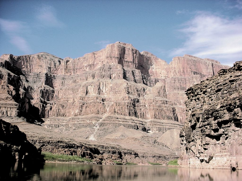
Figure (above): Beds in the Grand Canyon, AZ.
2) “Beds” are separated by “bedding planes” - cm to m thick units of sedimentary rock that were deposited approximately horizontally (beds) and are separated by approximately horizontal planes (bedding planes); the rocks typically weather more along these planes. Beds are usually fairly uniform or change gradationally in composition. Bedding planes usually represent breaks in sedimentation or changes in grain size. In other words, they usually represent changes in flow characteristics.
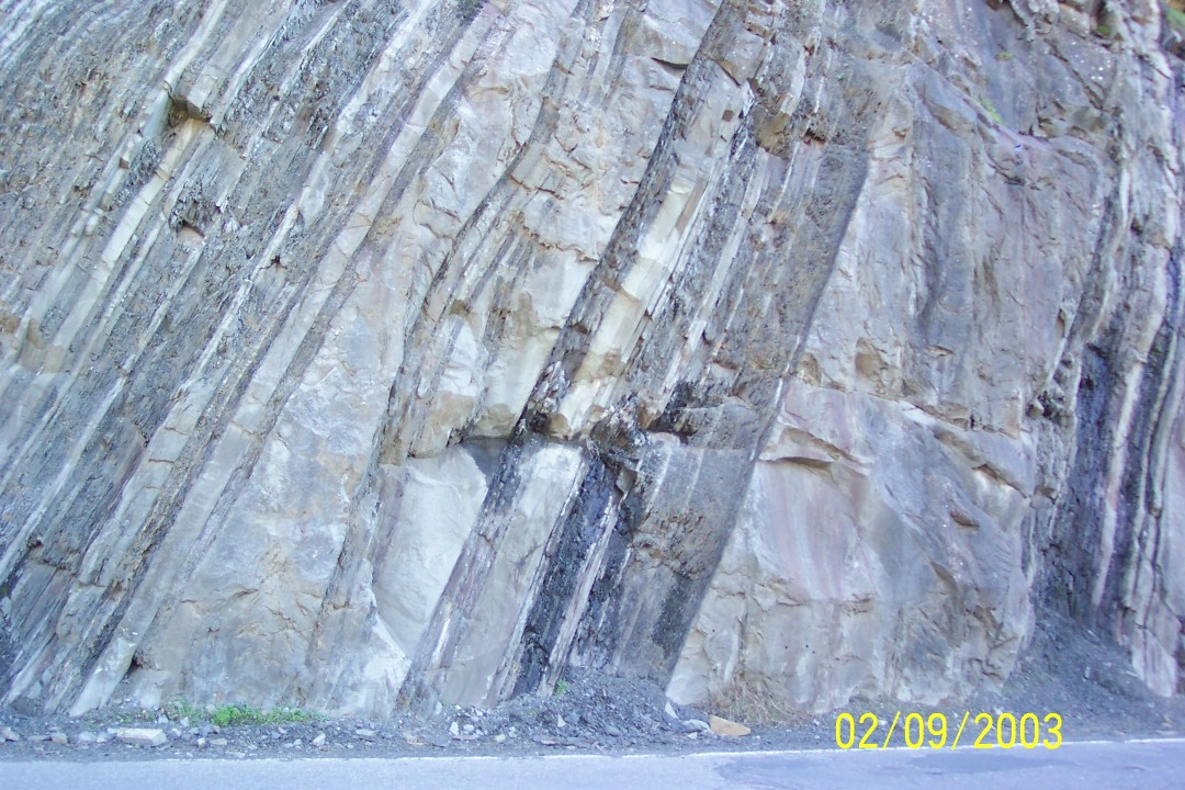
Figure (above): Turbidite beds and bedding planes along the road near Cache Creek, CA. They were originally deposited about horizontally and were tilted due to tectonic activity.
3) "Laminae" are color, composition, or grain size variations defining surfaces within a bed. They typically represent variations in flow velocity, sediment supply, sediment composition, etc. Planar Laminae are parallel to bedding, e.g. planar and deposited approximately horizontally.
4) "Cross Lamination”, "Cross Stratification" or "Cross Bedding" are laminations or layers that are oriented obliquely to bedding. They truncate older laminae and are truncated by younger laminae. The erosional surfaces that separate “sets” of similarly oriented laminae are called “bounding surfaces”. There are lots of subdivisions of cross stratification; different types represent different types of bedforms and different flow conditions.
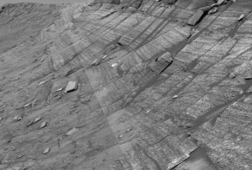
Figure (above): Burns Cliff on Mars photographed by the rover Opportunity: The upper part of the image has planar lamination, and the lower part to the far left has cross lamination or stratification. (The very straight line running diagonally from top to bottom is a seam where two images were merged together.)

Figure (above): Trough cross stratification in sandstone. The photos show two views of the same rock with the scale bar at the same place in both photos. Note how the geometry of the layers is different in the two views. (Bars in scale represent 1 cm each.)
Other examples of dune cross stratification can be found here.
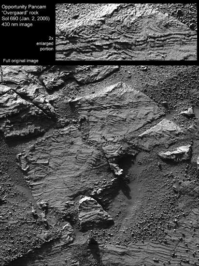
Figure (above): Ripple cross lamination on Mars, taken by NASA's Opportunity Mars Exploration Rovers team.
Bedforms
When sediments get deposited from turbulent flows, the sediment interacts with the geometry of the flow. Depending on the flow speed, turbulence, and sediment characteristics, different structures or bedforms develop.
Bed Geometry and Flow Separation
Until now, we have been implicitly assuming that the bases of beds are flat and smooth, but if sediment is present, they are not. If you start with a smooth bed of sand and increase water speed above it, irregularities form from irregularities in the flow. Irregularities in sand develop into ripples if the flow speed is appropriate. First, a few grains pile up. Once the height of the pile is several grains high, there is a flow shadow down stream of them, and the laminar sublayer detaches from the base of the flow. The water has enough momentum that it does not hug the bed surface and instead, goes shooting out over the top. This point is called the separation point. The water flows forward and downward and reconnects with the bed at the attachment point. At the attachment point, water is flowing directly towards the sediment with a lot of force. This force moves the grains and causes erosion. In contrast, the area between the separation point and the attachment point has a very low flow speed. In fact, there can be back eddies, where the flow is moving upstream. Thus, sediment transport is very irregular along the bedding surface at a local scale.
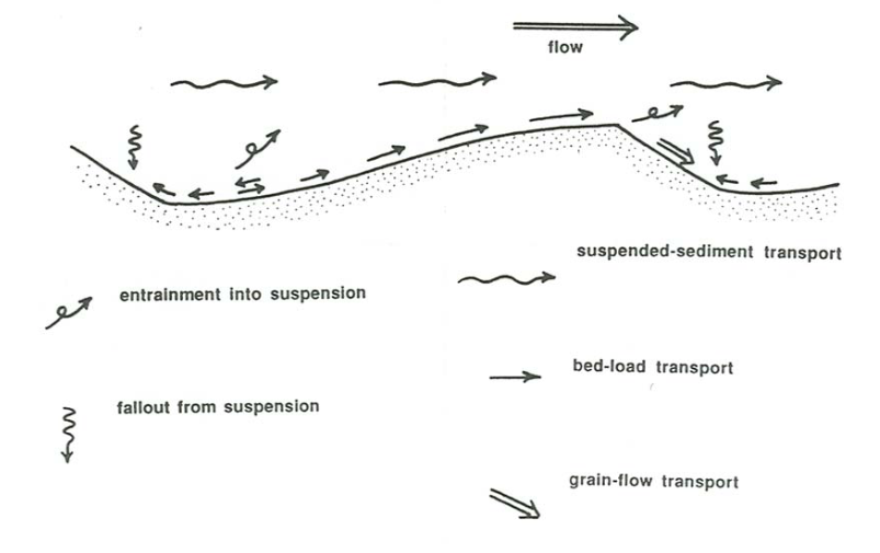
Figure (above): Sketch of fluid flow and sediment transport over a ripple or dune. Note that the suspended sediment does not influence the formation of the bedform. Only bedload (rolling/traction and saltating) grains do. (From Southard, LibreTexts)
The video below shows sediment transport over a ripple.
Sediment Transport Over a Ripple
Sediment grains are mobilized at the attachment point - more so than in normal flow because the water is shooting directly into the sediment - and the grains are moved downstream by saltation and traction. As the flow becomes parallel to the sediment surface again, its ability to transport sediment decreases. Thus, the grains tend to pile up and a new mound forms. This gives a periodic chain of mounds - the beginnings of ripples. As flow continues, grains roll and saltate up the stoss (upcurrent) side of the ripples. Once they pass the crest, they reach the low flow on the lee side of the ripple. The larger grains settle out and roll partway down the slope; this is the site of net deposition. As the process of deposition on the lee side and erosion on the stoss side continues, the ripples migrate downstream. If there is net deposition of sediment, the ripples leave behind distinctive dipping layers between two erosional surfaces that can be preserved in the rock record. These layers slope downstream and are one type of cross lamination.
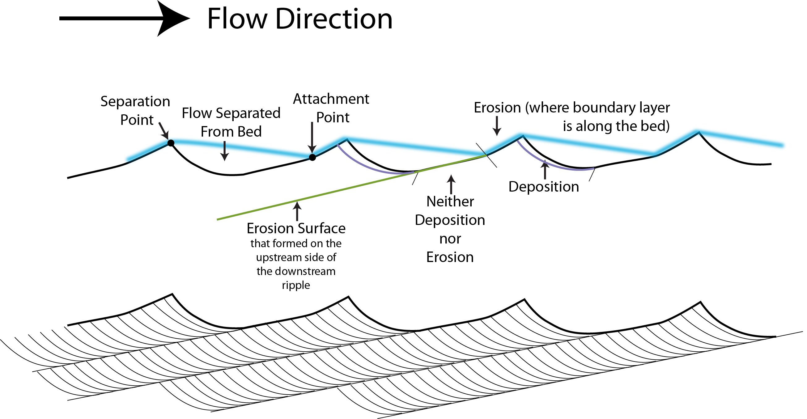
Figure (above): A sketch of a ripple or dune showing the locations of deposition and erosion relative to the geometry of the flow and its connection to cross lamination.
The geometry of the flow tracks the separation and attachment points. Erosion can only occur where there the bed shear stress is high enough to move sediment. In other words, the the main flow must be near the sediment surface. Sediment accumulates into a deposit in the flow shadow downstream of the ripple or dune crest; sediment accumulates in the flow detachment zone. Laminae are visible where deposition occurs due to variations in flow speed which cause variations in grain sizes transported and deposited.
Sets of laminae are separated by erosion surfaces which form on the upstream side of the ripples or dunes. They represent deposition on the downstream side. The shape of the laminae reflects the shape of the depositional surface and the geometry of sediment accumulation. If the depositional surface is curved, the base of the laminae is curved. Laminae thicken into areas with higher deposition rates. Also, the maximum distance between erosion surfaces is less than the maximum height of the ripple or dune; since the erosion surfaces form on the upstream sides, they are closer to the underlying erosion surfaces than the ripple/dune crests. Thus, the maximum separation of erosion surfaces represents a minimum height for the ripple or dune.
Watch the USGS bedform movies described at: Sedimentary Structures Lab and Homework Resources
The video below shows migration of a ripple in a flume.
Bedforms and Flow Velocity
The size and shape of subaqueous bedforms depends on flow strength and grain size and can be used to interpret ancient flow characteristics in a depositional environment from looking at sedimentary rocks. The relationships between flow speed and bedforms have been determined in flume experiments. This is the sequence of structures seen in relatively shallow flows:
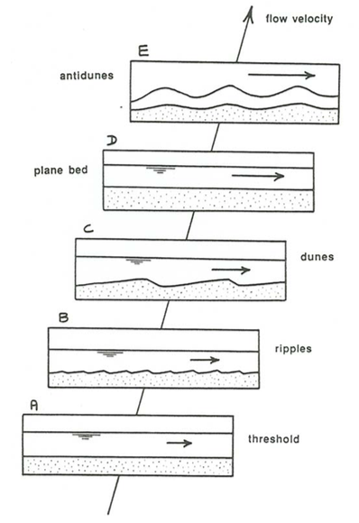
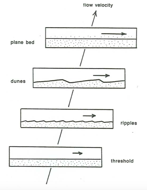
Figure (above; from Southard-LibreTexts): Sketchs showing the sequence of bed features in a flume with increasing flow speed over medium sand in a shallow flow (left) and a flow with a top that keeps the upper water surface flat (right). Antidunes only form when the surface of the flow can interact with the bed (left). If the water is too deep, only plane (or planar) bedding forms (right).
The video below shows the evolution of a flat bed into ripples and then dunes. Note the two distinct bedform sizes, particularly later in the video where small ripples are forming on the backs of the larger dunes.
The bedforms that develop in any given flow-sediment combination depend on the Reynolds Number as well as the grain size. Bedforms require bedload transport of sediment to form; suspended grains do not create them. Thus, they form in grain sizes of silt and larger, as long as the flow speed is not so large that the grains are mostly transported in suspension. In addition, they depend on both flow speed and flow depth. Most of the experiments have been done in flows that are < 1 m in depth for practical reasons. However, we will use plots that show only grain size and flow speed. This creates a disconnect between the bedform diagram below and the Hjulstrom Diagram. The average Reynolds Number for the bedform diagram is lower than that in the Hjulstrom Diagram because the flow depths are lower.
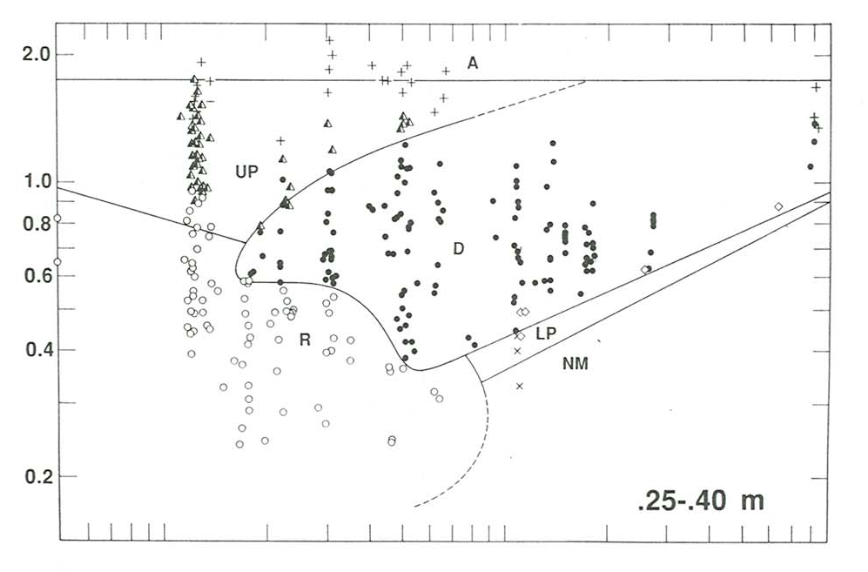
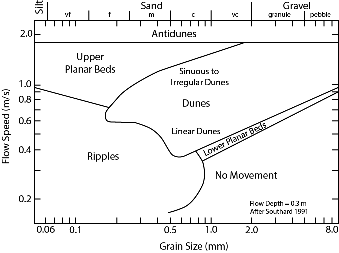
Figures Top: (from Southard-LibreTexts; note that he wrote the axis labels by hand).The type of bedform varies with both the size of the grains and the average flow speed. The circles, triangles, crosses, etc. mark conditions that were tested in flume experiments. These data were used to create the diagram. Note that right near the boundaries, experiments can give slightly different results due to variations in the flows. Fluctuations are common, and right at the boundaries, the bed geometry is often unstable. For practical reasons, all experiments were performed in flows with a depth of less than 1 m. This means that the flow speed for no movement is different than it is in the Hjulstrom Diagram. Southard provides data on how the bedforms change with flow depth in this chapter. Bottom: A summary of the bedforms at different flow speeds and grainsizes (redrawn by Sumner after Southard, 1991).
Ripples
(crest-to-crest distance - or wavelength - of less than 50 cm and heights of less than 4 cm)
The minimum flow for ripples is determined by the minimum velocity for sediment transport. Once this flow speed is reached, ripples form if the grains are sufficiently fine and are transported as bedload. The formation of ripples is controlled by the characteristics of the boundary layer. In particular, the laminar sublayer is a key component at these flow speeds. At grain sizes of coarse sand (~0.8 mm) and larger, the bed roughness increases, which disrupts the laminar sublayer. Thus, ripples do not form in coarser grained sediments (See Figure below).
At the lowest transport speeds for grains that form ripples, ripple crests tend to be linear. At higher flow speeds, irregular crests develop, with some parts of the ripples moving faster than others. This creates variations in the ripple cross lamination geometry. Eventually, too much erosion occurs at the crests of the ripples and the ripples flatten out. Dunes or upper planar beds develop, depending on the grain size.
Dunes
(60 cm-100’s m wavelength and 10’s of cm to meters in height)
Dunes and ripples behave similarly at the level of detail that I have been describing them. Their cross stratification geometries are similar. However, dunes are larger than ripples; there is a distinct break in size between the two. In addition, dunes form in grain sizes ranging from fine sand to pebbles, whereas ripples form in silt to coarse sand. Dunes do not form in finer grained sediment because the grains tend to be transported in suspension if they are lifted above the laminar sublayer in the flow.
For grain sizes of fine sand (~0.15 mm) and coarser, dunes develop as ripples flatten out. Turbulence in the flow creates large scale irregularities grow into dunes. The basic ideas of dune and ripple formation are the same. The difference is that the area of flow separation is much larger and more turbulent for dunes. Roller vortexes (e.g. upstream flows along the lee sides of dunes) are common, and the upstream flow can be strong enough to form ripples that migrate upstream on the lee side of dunes. As flow speeds increase, the dunes change morphology. The wavelength or spacing between dunes increases, and they go from having straight crests ("2D" bedforms) to sinuous crests (or even irregular crests, "3D bedforms"). These changes in morphology reflect changes in the structure of turbulence in the flows.
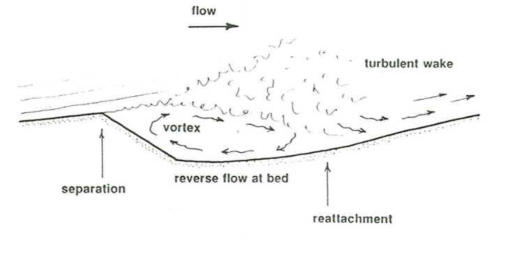
Figure (above; from Southard-LibreTexts): Sketch of a roller vortex on the lee side of a dune.
As the flow speed increases even more, the stoss sides of dunes experience so much erosion that they flatten out to form planar beds.
Planar/Flat Lamination
Planar lamination forms when the flow is strong enough that the beds flatten out. The momentum of the transported grains and fluid are high enough that they tend to move horizontally, eroding any irregularities in the bed. This zone of planar lamination is called “upper flow regime”. (Why “upper”? - there is a zone of planar lamination in coarse grained sediment at low flow velocities.)
Antidunes
Antidunes form at flow speeds greater than planar lamination when shallow water moves very quickly (Putah Creek in flood; tidal channels; creeks flowing across beaches). Irregularities form on the planar beds, but there is no flow separation. Instead, the water surface mimics the bedding surface. On the down flow side of the antidunes, there is a very strong erosional force (from the Bernoulli Effect) and sediment gets plastered onto the upstream side. Thus, antidunes produce laminae that dip upstream, and they migrate upstream (anti normal dune behavior). Sediment is still transported downstream; it is just the peak of the dune itself that moves upstream. At even higher flow, the waves on the surface of the water break, and the dunes flatten out. Antidunes are rarely preserved in the rock record because they are unstable bedforms and are reworked into other sedimentary structures as the flow speed decreases.
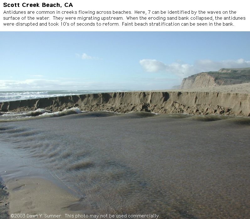
Figure (above): Photograph of antidunes in a creek flowing across Scott Creek Beach in a channel. The surface of the water has waves in it that are associated with antidunes on the sediment surface.
Variations in Geometry and Bedform
Dunes and ripples are often irregular in plan view. This affects the geometry of the cross stratification/lamination. The laminae are always approximately parallel to the dip on the lee sides of the ripples or dunes. If the direction that these dip varies, the orientation of the laminae also varies. When looking at deposited cross stratification/lamination, these variations appear as variable dips in the laminae because you are viewing them at different angles.
Watch the USGS bedform movies described at Sedimentary Structures Lab and Homework Resources for examples of how bedform morphology affects the geometry of the resulting cross stratification.
Distinguishing Between Ripple Cross Lamination and Dune Cross Stratification
If the distance between erosion surfaces defining cross sets is greater than a few centimeters, the cross stratification has to be from a dune. Ripples are only a few centimeters tall, and they cannot create laminae that are higher than the ripple crest-to-trough distance. Thus, if cross sets are greater than a few centimeters high, the cross stratification must be from dunes. However, if the cross sets are only one centimeter high, the cross stratification could be due to either ripples or dunes. It is possible for ALL sediment to be eroded as a dune migrates, leaving no cross stratification. If only a small amount of sediment accumulates, the cross sets might be only a centimeter high, much like ripples. In the field, grain size variations and changes in cross stratification along an outcrop can help you distinguish between ripples and dunes in a case like this. For example, you could look for an instance where the cross stratification is more than a few centimeters high. If you did not find one, that might suggest ripple cross lamination rather than dune cross stratification. Or maybe the grain size is wrong for one or the other.
Other Types of Flows
Not all flows are uniform in one direction. For example, waves move water back and forth, transporting sand back and forth. Because the transport direction varies through time, the orientation of cross laminations vary through time. Note that wave ripple lamination dips in two directions and the ripple crests are symmetric rather than steeper on the lee slope than the stoss slope. Flows can also be irregular due to combinations of currents and waves, etc. Some of these flows are very characteristic of specific environments, for example, storm-influenced beaches. The structures they produce are very useful for interpreting ancient rocks, and we will highlight them as we discuss different sedimentary environments.
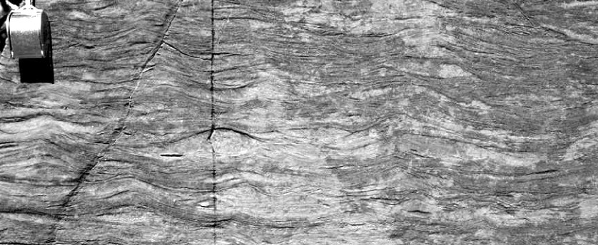
Figure (above): Wave ripple cross lamination in an Archean carbonate. Note that laminae dip in both directions. Some ripple crests are preserved. The hand lens is about 1.5 cm across.
The first video below shows transport across the crest of a wave ripple. It is easier to see the darker grains move. When they move just past the crest and stop, most of the grains are rolling (in traction) and the crest tends to have a sharp peak. In contrast, when larger waves come by, more grains are transported via saltation (and suspension) and the crest is more rounded.
The video below shows "interference" ripples. They form in places that have waves moving in multiple directions. In this case, the waves are going around stromatolites (the darker blobs). The suspended sediment shows that the flow is in multiple directions, and the amount of sediment varies depending on the size of the waves.