
5.1: Sandstones
- Page ID
- 26411

\( \newcommand{\vecs}[1]{\overset { \scriptstyle \rightharpoonup} {\mathbf{#1}} } \)
\( \newcommand{\vecd}[1]{\overset{-\!-\!\rightharpoonup}{\vphantom{a}\smash {#1}}} \)
\( \newcommand{\dsum}{\displaystyle\sum\limits} \)
\( \newcommand{\dint}{\displaystyle\int\limits} \)
\( \newcommand{\dlim}{\displaystyle\lim\limits} \)
\( \newcommand{\id}{\mathrm{id}}\) \( \newcommand{\Span}{\mathrm{span}}\)
( \newcommand{\kernel}{\mathrm{null}\,}\) \( \newcommand{\range}{\mathrm{range}\,}\)
\( \newcommand{\RealPart}{\mathrm{Re}}\) \( \newcommand{\ImaginaryPart}{\mathrm{Im}}\)
\( \newcommand{\Argument}{\mathrm{Arg}}\) \( \newcommand{\norm}[1]{\| #1 \|}\)
\( \newcommand{\inner}[2]{\langle #1, #2 \rangle}\)
\( \newcommand{\Span}{\mathrm{span}}\)
\( \newcommand{\id}{\mathrm{id}}\)
\( \newcommand{\Span}{\mathrm{span}}\)
\( \newcommand{\kernel}{\mathrm{null}\,}\)
\( \newcommand{\range}{\mathrm{range}\,}\)
\( \newcommand{\RealPart}{\mathrm{Re}}\)
\( \newcommand{\ImaginaryPart}{\mathrm{Im}}\)
\( \newcommand{\Argument}{\mathrm{Arg}}\)
\( \newcommand{\norm}[1]{\| #1 \|}\)
\( \newcommand{\inner}[2]{\langle #1, #2 \rangle}\)
\( \newcommand{\Span}{\mathrm{span}}\) \( \newcommand{\AA}{\unicode[.8,0]{x212B}}\)
\( \newcommand{\vectorA}[1]{\vec{#1}} % arrow\)
\( \newcommand{\vectorAt}[1]{\vec{\text{#1}}} % arrow\)
\( \newcommand{\vectorB}[1]{\overset { \scriptstyle \rightharpoonup} {\mathbf{#1}} } \)
\( \newcommand{\vectorC}[1]{\textbf{#1}} \)
\( \newcommand{\vectorD}[1]{\overrightarrow{#1}} \)
\( \newcommand{\vectorDt}[1]{\overrightarrow{\text{#1}}} \)
\( \newcommand{\vectE}[1]{\overset{-\!-\!\rightharpoonup}{\vphantom{a}\smash{\mathbf {#1}}}} \)
\( \newcommand{\vecs}[1]{\overset { \scriptstyle \rightharpoonup} {\mathbf{#1}} } \)
\(\newcommand{\longvect}{\overrightarrow}\)
\( \newcommand{\vecd}[1]{\overset{-\!-\!\rightharpoonup}{\vphantom{a}\smash {#1}}} \)
\(\newcommand{\avec}{\mathbf a}\) \(\newcommand{\bvec}{\mathbf b}\) \(\newcommand{\cvec}{\mathbf c}\) \(\newcommand{\dvec}{\mathbf d}\) \(\newcommand{\dtil}{\widetilde{\mathbf d}}\) \(\newcommand{\evec}{\mathbf e}\) \(\newcommand{\fvec}{\mathbf f}\) \(\newcommand{\nvec}{\mathbf n}\) \(\newcommand{\pvec}{\mathbf p}\) \(\newcommand{\qvec}{\mathbf q}\) \(\newcommand{\svec}{\mathbf s}\) \(\newcommand{\tvec}{\mathbf t}\) \(\newcommand{\uvec}{\mathbf u}\) \(\newcommand{\vvec}{\mathbf v}\) \(\newcommand{\wvec}{\mathbf w}\) \(\newcommand{\xvec}{\mathbf x}\) \(\newcommand{\yvec}{\mathbf y}\) \(\newcommand{\zvec}{\mathbf z}\) \(\newcommand{\rvec}{\mathbf r}\) \(\newcommand{\mvec}{\mathbf m}\) \(\newcommand{\zerovec}{\mathbf 0}\) \(\newcommand{\onevec}{\mathbf 1}\) \(\newcommand{\real}{\mathbb R}\) \(\newcommand{\twovec}[2]{\left[\begin{array}{r}#1 \\ #2 \end{array}\right]}\) \(\newcommand{\ctwovec}[2]{\left[\begin{array}{c}#1 \\ #2 \end{array}\right]}\) \(\newcommand{\threevec}[3]{\left[\begin{array}{r}#1 \\ #2 \\ #3 \end{array}\right]}\) \(\newcommand{\cthreevec}[3]{\left[\begin{array}{c}#1 \\ #2 \\ #3 \end{array}\right]}\) \(\newcommand{\fourvec}[4]{\left[\begin{array}{r}#1 \\ #2 \\ #3 \\ #4 \end{array}\right]}\) \(\newcommand{\cfourvec}[4]{\left[\begin{array}{c}#1 \\ #2 \\ #3 \\ #4 \end{array}\right]}\) \(\newcommand{\fivevec}[5]{\left[\begin{array}{r}#1 \\ #2 \\ #3 \\ #4 \\ #5 \\ \end{array}\right]}\) \(\newcommand{\cfivevec}[5]{\left[\begin{array}{c}#1 \\ #2 \\ #3 \\ #4 \\ #5 \\ \end{array}\right]}\) \(\newcommand{\mattwo}[4]{\left[\begin{array}{rr}#1 \amp #2 \\ #3 \amp #4 \\ \end{array}\right]}\) \(\newcommand{\laspan}[1]{\text{Span}\{#1\}}\) \(\newcommand{\bcal}{\cal B}\) \(\newcommand{\ccal}{\cal C}\) \(\newcommand{\scal}{\cal S}\) \(\newcommand{\wcal}{\cal W}\) \(\newcommand{\ecal}{\cal E}\) \(\newcommand{\coords}[2]{\left\{#1\right\}_{#2}}\) \(\newcommand{\gray}[1]{\color{gray}{#1}}\) \(\newcommand{\lgray}[1]{\color{lightgray}{#1}}\) \(\newcommand{\rank}{\operatorname{rank}}\) \(\newcommand{\row}{\text{Row}}\) \(\newcommand{\col}{\text{Col}}\) \(\renewcommand{\row}{\text{Row}}\) \(\newcommand{\nul}{\text{Nul}}\) \(\newcommand{\var}{\text{Var}}\) \(\newcommand{\corr}{\text{corr}}\) \(\newcommand{\len}[1]{\left|#1\right|}\) \(\newcommand{\bbar}{\overline{\bvec}}\) \(\newcommand{\bhat}{\widehat{\bvec}}\) \(\newcommand{\bperp}{\bvec^\perp}\) \(\newcommand{\xhat}{\widehat{\xvec}}\) \(\newcommand{\vhat}{\widehat{\vvec}}\) \(\newcommand{\uhat}{\widehat{\uvec}}\) \(\newcommand{\what}{\widehat{\wvec}}\) \(\newcommand{\Sighat}{\widehat{\Sigma}}\) \(\newcommand{\lt}{<}\) \(\newcommand{\gt}{>}\) \(\newcommand{\amp}{&}\) \(\definecolor{fillinmathshade}{gray}{0.9}\)Sandstones are clastic sedimentary rocks that are composed largely of sand-sized grains (>50% particles between 1/16 and 2 mm diameter). Sandstones make up approximately 14% of sedimentary rocks and can be found in a wide variety of depositional environments including alluvial fans, rivers and floodplains, beaches, and submarine fans. Porous sandstones can form important reservoirs for water and hydrocarbons; homogenous, well-cemented sandstones are commonly used as building stones.
Methods
Although much information can be gained with a hand lens and an acid bottle, sandstones are best studied in thin section with a petrographic microscope that has polarizing filters. The major components of sandstones include sand-sized framework grains and interstitial areas that originally contained either muddy interstitial matrix and/or open pore space. During diagenesis, mineral cements may precipitate into pore space.
Petrographic Microscopes
If you want a quick refresher on use of the petrographic microscope, see the YouTube video embedded below and the resources are provided at the end of this chapter.
Video \(\PageIndex{1}\): Review of petrography fundamentals.
Rocks and Minerals in Thin Section
The combination of thin sections (30 micron thick slivers of rock glued to a glass microscope slide) and petrographic microscope with polarizing filters can provide significant information and insight into rocks and minerals. In thin section, we can use the following properties to identify minerals:
- Color (in plane polarized light) - the hue observed in a mineral. It results from the selective absorption of certain wavelengths of light due to the mineral’s composition and crystal structure. Color can vary due to impurities or alteration.
- Pleochroism (in plane polarized light) - the change in color observed in an anisotropic mineral when the stage is rotated. It occurs because the mineral absorbs light differently along different crystallographic directions. Pleochroism can range from weak to strong and can vary to include two or three colors depending on the mineral’s optical properties.
- Interference colors (crossed polars) - colors that result from the splitting of light into two rays that travel at different speeds through a mineral, causing a phase difference when they recombine. The resulting colors correspond to a specific order on Michel-Lévy’s interference color chart (see link below).
- Relief - the degree to which a mineral stands out relative to its surrounding minerals or the mounting medium. It is a function of the difference in refractive index (RI) between the mineral and its surroundings. High-relief minerals appear strongly outlined with pronounced shadows at grain boundaries, while low-relief minerals blend with their surroundings.
- Twinning - refers to the presence of intergrown crystal domains within a mineral that share a specific crystallographic relationship but have different optical orientations. It is observed under both plane-polarized light (PPL) and cross-polarized light (XPL) in a petrographic microscope. Twinning can appear as parallel, crosshatched, or wedge-shaped patterns.
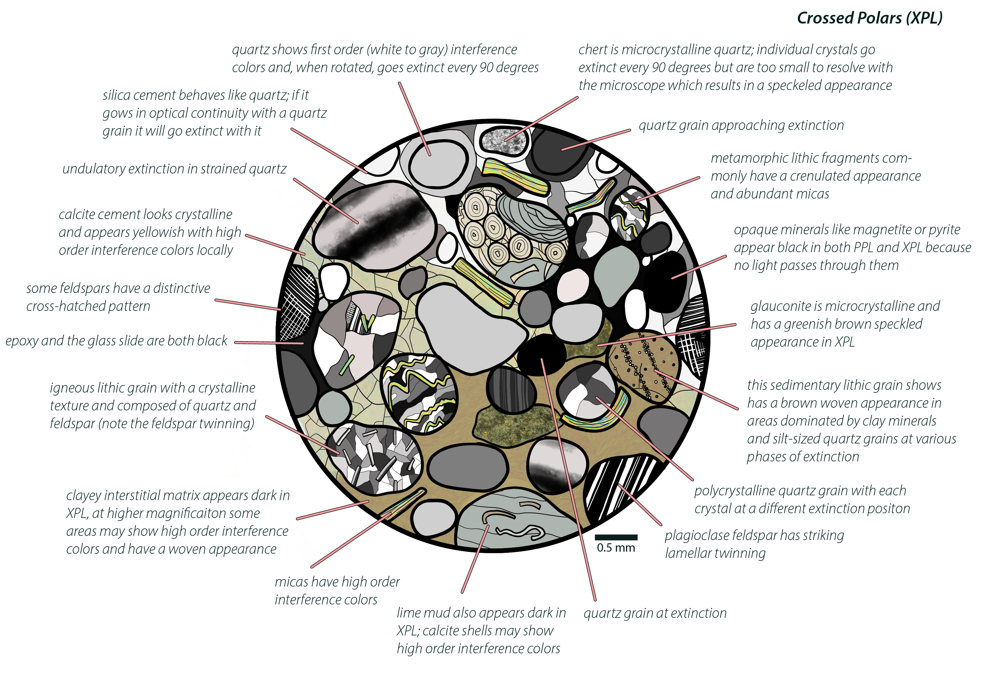
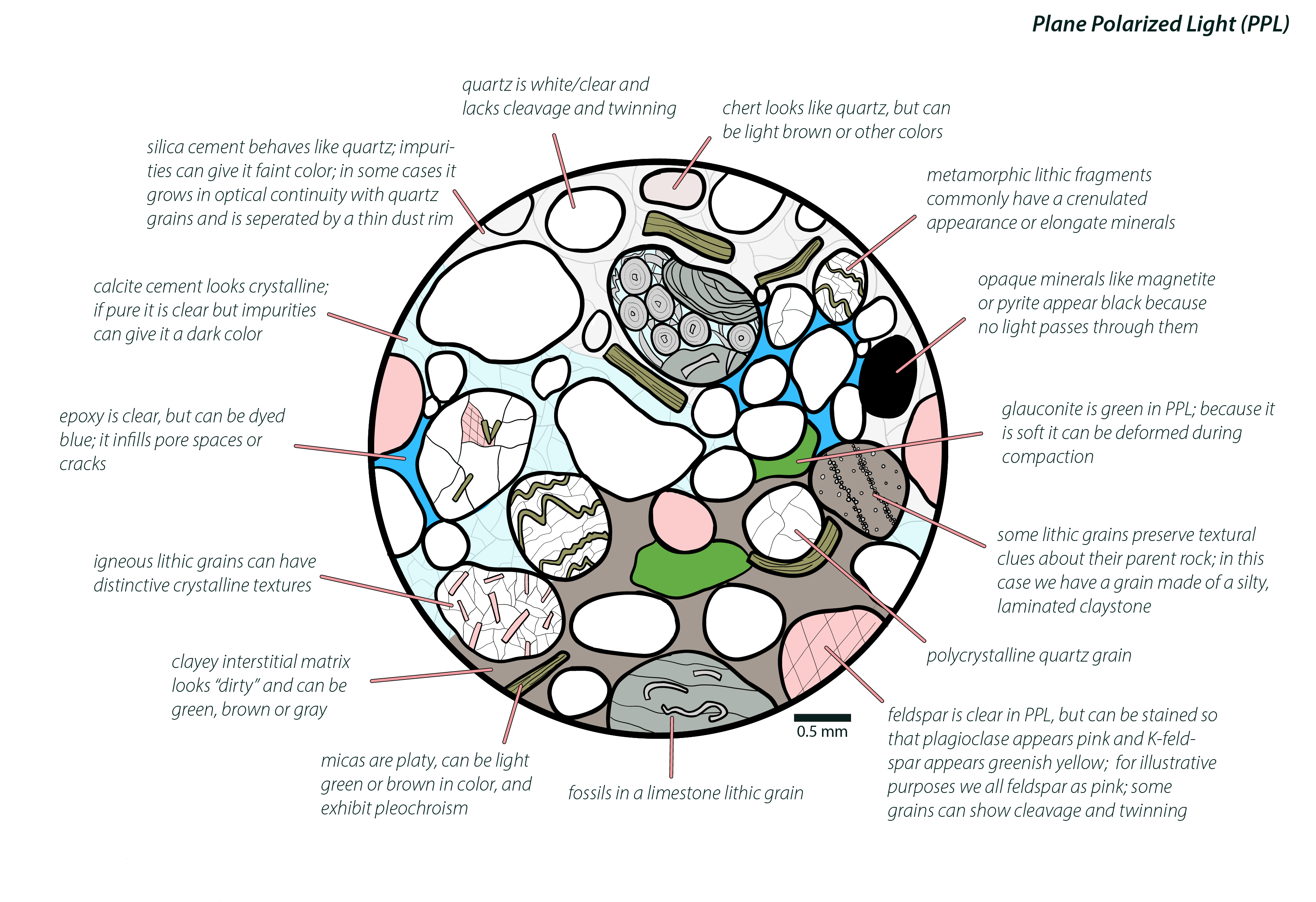
Figure \(\PageIndex{1}\): Summary diagram showing the most common elements of clastic sedimentary rocks in thin section (after Page Quinton via Wikimedia Commons; CC BY-SA 4.0). Note that the same field of view is shown in both, but that the top image shows what the components look like in plane polarized light and the bottom one shows what they look like with crossed polars.
Framework Grains
Framework grains are sand-sized particles that make up the majority of a sandstone. These particles were transported by a moving current and came to rest when turbulence and bedload transport ceased. Grains composed of quartz, feldspar, or lithic fragments (rock fragments) are the most common type of sand grains and their relative abundance is used to classify the sandstone; all others are considered accessory minerals.
Quartz
Given its resistance to chemical weathering and abundance in continental crust, quartz is the most common framework grain in most sandstones. In hand sample, quartz grains are easily identified by its glassy appearance and lack of cleavage. In thin section, if the quartz grain is made from a single crystal (monocrystalline) it will appear clear/white in plane polarized light (PPL) and uniformly go extinct every 90° in cross polarized light (XPL). Grains derived from an igneous source may actually be composed of several interlocking crystals (polycrystalline quartz) and those from a metamorphic source may show undulatory extinction. Note that polycrystalline quartz grains (and chert, see lithic grains below) can be counted as quartz if the goal is to focus on compositional maturity. Alternately, polycrystalline quartz and chert can be counted as lithics if the goal is to focus on the composition of the source rocks.
Feldspar
Feldspar grains can be particularly abundant in sandstones derived from granitic source areas and/or in arid climates with limited chemical weathering. Feldspar grains appear clear in PPL and commonly exhibit twinning in XPL. In both cases, cleavage may give the external form and internal planes of weakness a blocky appearance. When making thin sections, it is possible to stain them to help distinguish feldspars from other broadly similar minerals. If stained with cobaltinitrite, potassium feldspar will take on a yellow color; if stained with barium rhodizonate, plagioclase feldspar will turn red.
Lithics
Lithic grains are sand-sized particles of preexisting metamorphic, sedimentary, or igneous rocks. These grains have a variety of appearances, generally they can be composed of multiple minerals, have a complex fabric, and/or have a distinctive composition (ex: carbonate). As discussed above, one could count polycrystalline quartz and chert as lithic fragments if the goal of the analysis was to emphasize source (rather than compositional maturity).
Accessory Minerals
All other sand-sized particles are classified as accessory minerals. Muscovite and biotite micas are common accessory minerals in sediment found adjacent to crystalline source areas. The micas are easily identified in hand sample as particularly large, platy grains concentrated along bedding planes; in thin section they appear as large play grains with obvious cleavage and high order birefringence colors in XPL. Magnetite, rutile, tourmaline, zircon, and other resistant minerals may be abundant in some areas.


Interstitial Material
Matrix
Matrix is fine-grained, clayey material between the framework grains in some sandstones. The origin of matrix is not well understood; possibilities for its formation include deposition of mud in protected areas between grains, deposition as thin layers that are later homogenized, larger particles of flocculated clay, or alteration products derived from unstable grains (pseudomatrix). Regardless of its exact origin, matrix (or its precursor) forms at the time of deposition. Matrix-rich sandstones are commonly dark colored in hand sample; matrix appears as dark, semi-translucent, amorphous material between sand grains in PPL and as dark material with a fine “woven” texture that may have high-order birefringence colors in XPL.

Pore space
If not clogged with muddy matrix, the interstitial areas between sand grains (pore spaces) are voids filled with water or air. Although sand spherical grains organized into a cubic stacking pattern has a theoretical maximum of 47.6% pore space, actual porosity values of 5-25% are more typical. During the manufacture of thin sections, pore space is commonly filled with epoxy which appears clear or blue (if dyed) in PPL and black in XPL.

Cement
During diagenesis, material dissolved in groundwater commonly precipitate into pore spaces forming mineral cements that bind the sandstone together. The two most common cements in sandstones are silica and calcite. Silica cement commonly nucleates on the surface of quartz grains; in PPL dust rims may delineate the edge of the grains; the silica commonly grows in optical continuity with the grain and may go extinct with it as the microscope stage is rotated in XPL. Although calcite cement appears similar to silica in PPL, it is easily distinguished by high order interference colors in XPL. Beyond these common cements, some sandstones may be cemented with pyrite, hematite, gypsum, kaolinite, illite, or a variety of other minerals.

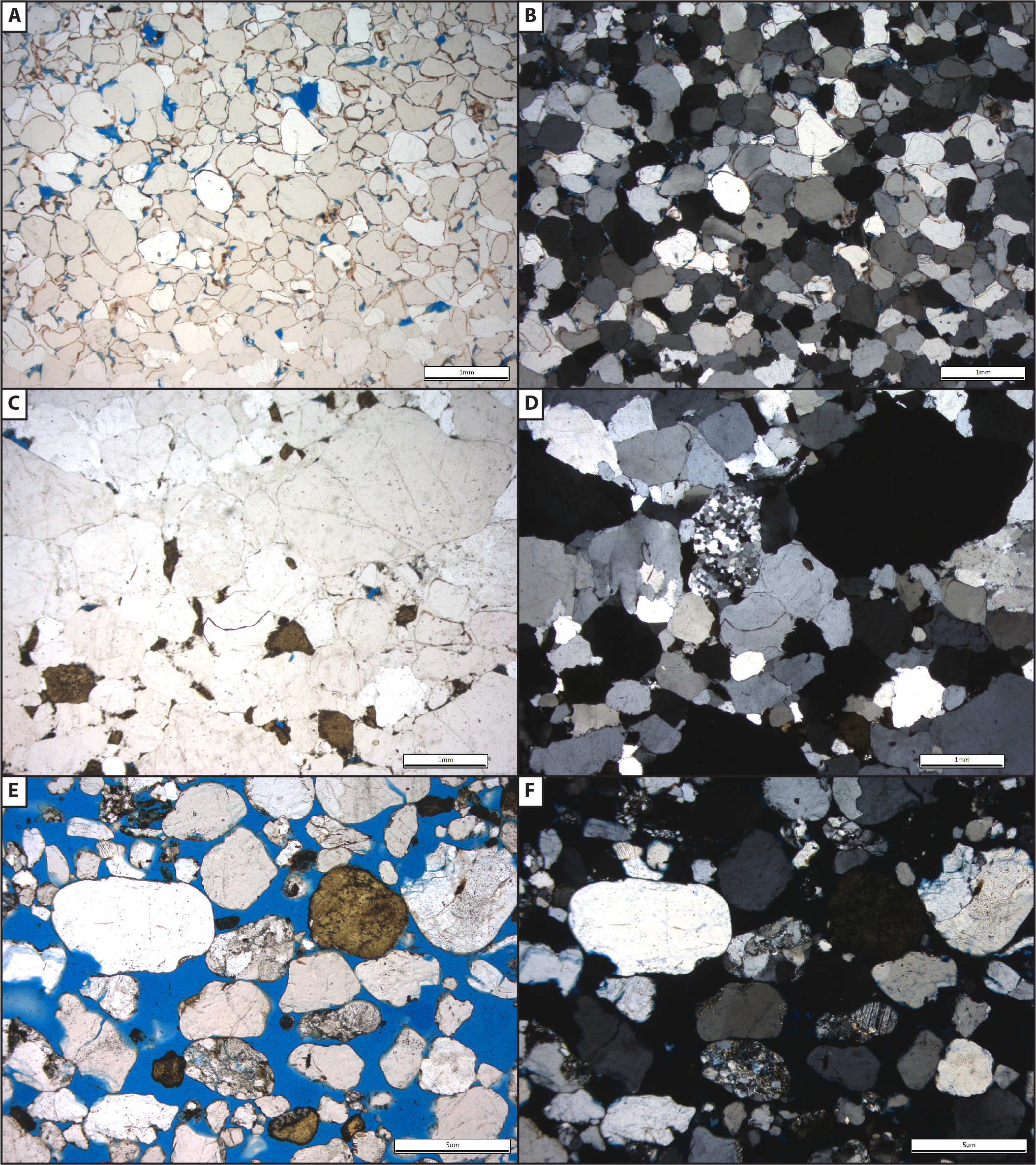
Figure \(\PageIndex{9}\): Photomicrographs of silica and calcite cement; images in plane polarized light are on the left and cross polarized light on the right (all images from Michael C. Rygel via Wikimedia Commons; CC BY-SA 4.0). A & B) Silica cement that grew in optical continuity with quartz grains; grain boundaries are highlighted by hematite dust rims. C & D) Coarse calcite cement between chert grains. Note the high order birefringence colors. E & F) A quartz arenite sandstone with silica cement predominantly filling interstitial areas on the left and calcite cement largely restricted to the right.
Classification
Older literature and many introductory textbooks recognize three main types of sandstone: quartz sandstone (quartz-rich), arkose (feldspar-rich) sandstone, and greywacke (muddy) sandstone. Although useful when applied to the type of endmember sandstones included in rock and mineral kits, these terms are ambiguous and do not capture much of the variability present in the field.
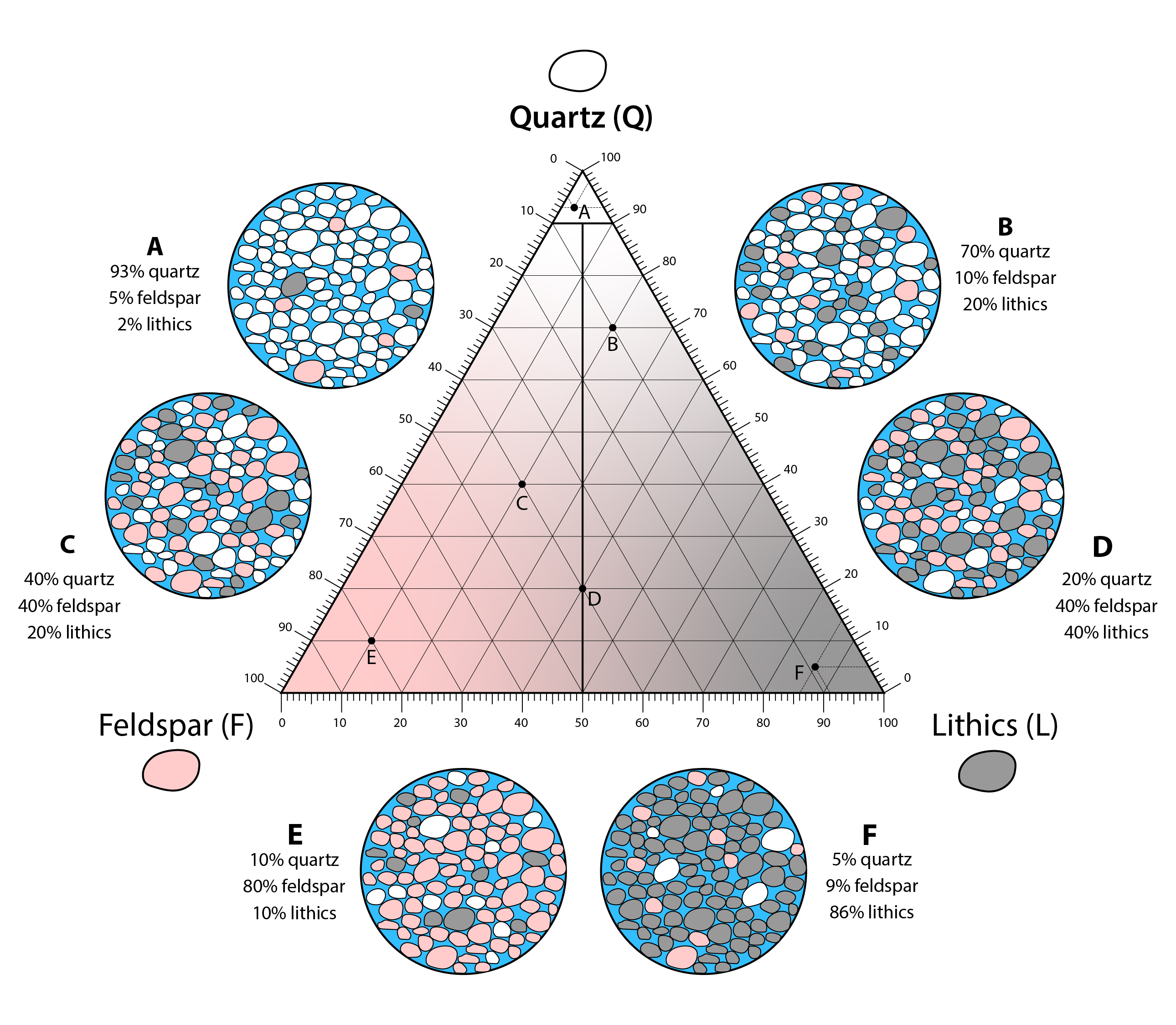
Dott (1964) proposed a simple two-word naming scheme where the first word (quartz, feldspathic, or lithic) represents the relative abundance of quartz, feldspar, and lithic framework grains and the second word represents the abundance of interstitial matrix (arenite if <10% matrix or wacke if >10% matrix). This scheme allows for a name that speaks to the compositional maturity (framework grain composition) and textural maturity (amount of mud) of the rock.
A few things to consider when classifying sandstones using this scheme include:
- Only quartz, feldspar, and lithic framework grains are used for naming; plotting composition on the ternary diagram requires that their relative abundances be normalized to 100%.
- Cement is a diagenetic feature and not used to name sandstones.
- The amount of matrix is estimated for the entire volume of the rock. This represents the entire field of view in thin section. In hand sample, wackes are distinguished by the presence of dark, fine-grained material rather than glassy or shiny cement.
- Although proper classification requires point counting of ~300 sand grains in thin section, quick visual estimation using a hand lens or thin section usually produces satisfactory results.


Readings and Resources
- Short video about stains for feldspars and carbonate minerals
- Discussion about provenance, plate tectonics, and what to do with polycrystalline quartz and chert
- Michel-Lévy interference color chart issued by Zeiss Microscopy
- Introduction to Petrology OER textbook with great explanations and videos about thin sections and the petrographic microscope
- Dott, R.H., 1964, Wacke, Graywacke and Matrix - What Approach to Immature Sandstone Classification?, Journal of Sedimentary Petrology, v. 34, p. 625-632
- Thin section analysis of oil reservoirs and source rocks
- Provenance and plate tectonics