11.1: Introduction
- Page ID
- 12937
\( \newcommand{\vecs}[1]{\overset { \scriptstyle \rightharpoonup} {\mathbf{#1}} } \)
\( \newcommand{\vecd}[1]{\overset{-\!-\!\rightharpoonup}{\vphantom{a}\smash {#1}}} \)
\( \newcommand{\dsum}{\displaystyle\sum\limits} \)
\( \newcommand{\dint}{\displaystyle\int\limits} \)
\( \newcommand{\dlim}{\displaystyle\lim\limits} \)
\( \newcommand{\id}{\mathrm{id}}\) \( \newcommand{\Span}{\mathrm{span}}\)
( \newcommand{\kernel}{\mathrm{null}\,}\) \( \newcommand{\range}{\mathrm{range}\,}\)
\( \newcommand{\RealPart}{\mathrm{Re}}\) \( \newcommand{\ImaginaryPart}{\mathrm{Im}}\)
\( \newcommand{\Argument}{\mathrm{Arg}}\) \( \newcommand{\norm}[1]{\| #1 \|}\)
\( \newcommand{\inner}[2]{\langle #1, #2 \rangle}\)
\( \newcommand{\Span}{\mathrm{span}}\)
\( \newcommand{\id}{\mathrm{id}}\)
\( \newcommand{\Span}{\mathrm{span}}\)
\( \newcommand{\kernel}{\mathrm{null}\,}\)
\( \newcommand{\range}{\mathrm{range}\,}\)
\( \newcommand{\RealPart}{\mathrm{Re}}\)
\( \newcommand{\ImaginaryPart}{\mathrm{Im}}\)
\( \newcommand{\Argument}{\mathrm{Arg}}\)
\( \newcommand{\norm}[1]{\| #1 \|}\)
\( \newcommand{\inner}[2]{\langle #1, #2 \rangle}\)
\( \newcommand{\Span}{\mathrm{span}}\) \( \newcommand{\AA}{\unicode[.8,0]{x212B}}\)
\( \newcommand{\vectorA}[1]{\vec{#1}} % arrow\)
\( \newcommand{\vectorAt}[1]{\vec{\text{#1}}} % arrow\)
\( \newcommand{\vectorB}[1]{\overset { \scriptstyle \rightharpoonup} {\mathbf{#1}} } \)
\( \newcommand{\vectorC}[1]{\textbf{#1}} \)
\( \newcommand{\vectorD}[1]{\overrightarrow{#1}} \)
\( \newcommand{\vectorDt}[1]{\overrightarrow{\text{#1}}} \)
\( \newcommand{\vectE}[1]{\overset{-\!-\!\rightharpoonup}{\vphantom{a}\smash{\mathbf {#1}}}} \)
\( \newcommand{\vecs}[1]{\overset { \scriptstyle \rightharpoonup} {\mathbf{#1}} } \)
\(\newcommand{\longvect}{\overrightarrow}\)
\( \newcommand{\vecd}[1]{\overset{-\!-\!\rightharpoonup}{\vphantom{a}\smash {#1}}} \)
\(\newcommand{\avec}{\mathbf a}\) \(\newcommand{\bvec}{\mathbf b}\) \(\newcommand{\cvec}{\mathbf c}\) \(\newcommand{\dvec}{\mathbf d}\) \(\newcommand{\dtil}{\widetilde{\mathbf d}}\) \(\newcommand{\evec}{\mathbf e}\) \(\newcommand{\fvec}{\mathbf f}\) \(\newcommand{\nvec}{\mathbf n}\) \(\newcommand{\pvec}{\mathbf p}\) \(\newcommand{\qvec}{\mathbf q}\) \(\newcommand{\svec}{\mathbf s}\) \(\newcommand{\tvec}{\mathbf t}\) \(\newcommand{\uvec}{\mathbf u}\) \(\newcommand{\vvec}{\mathbf v}\) \(\newcommand{\wvec}{\mathbf w}\) \(\newcommand{\xvec}{\mathbf x}\) \(\newcommand{\yvec}{\mathbf y}\) \(\newcommand{\zvec}{\mathbf z}\) \(\newcommand{\rvec}{\mathbf r}\) \(\newcommand{\mvec}{\mathbf m}\) \(\newcommand{\zerovec}{\mathbf 0}\) \(\newcommand{\onevec}{\mathbf 1}\) \(\newcommand{\real}{\mathbb R}\) \(\newcommand{\twovec}[2]{\left[\begin{array}{r}#1 \\ #2 \end{array}\right]}\) \(\newcommand{\ctwovec}[2]{\left[\begin{array}{c}#1 \\ #2 \end{array}\right]}\) \(\newcommand{\threevec}[3]{\left[\begin{array}{r}#1 \\ #2 \\ #3 \end{array}\right]}\) \(\newcommand{\cthreevec}[3]{\left[\begin{array}{c}#1 \\ #2 \\ #3 \end{array}\right]}\) \(\newcommand{\fourvec}[4]{\left[\begin{array}{r}#1 \\ #2 \\ #3 \\ #4 \end{array}\right]}\) \(\newcommand{\cfourvec}[4]{\left[\begin{array}{c}#1 \\ #2 \\ #3 \\ #4 \end{array}\right]}\) \(\newcommand{\fivevec}[5]{\left[\begin{array}{r}#1 \\ #2 \\ #3 \\ #4 \\ #5 \\ \end{array}\right]}\) \(\newcommand{\cfivevec}[5]{\left[\begin{array}{c}#1 \\ #2 \\ #3 \\ #4 \\ #5 \\ \end{array}\right]}\) \(\newcommand{\mattwo}[4]{\left[\begin{array}{rr}#1 \amp #2 \\ #3 \amp #4 \\ \end{array}\right]}\) \(\newcommand{\laspan}[1]{\text{Span}\{#1\}}\) \(\newcommand{\bcal}{\cal B}\) \(\newcommand{\ccal}{\cal C}\) \(\newcommand{\scal}{\cal S}\) \(\newcommand{\wcal}{\cal W}\) \(\newcommand{\ecal}{\cal E}\) \(\newcommand{\coords}[2]{\left\{#1\right\}_{#2}}\) \(\newcommand{\gray}[1]{\color{gray}{#1}}\) \(\newcommand{\lgray}[1]{\color{lightgray}{#1}}\) \(\newcommand{\rank}{\operatorname{rank}}\) \(\newcommand{\row}{\text{Row}}\) \(\newcommand{\col}{\text{Col}}\) \(\renewcommand{\row}{\text{Row}}\) \(\newcommand{\nul}{\text{Nul}}\) \(\newcommand{\var}{\text{Var}}\) \(\newcommand{\corr}{\text{corr}}\) \(\newcommand{\len}[1]{\left|#1\right|}\) \(\newcommand{\bbar}{\overline{\bvec}}\) \(\newcommand{\bhat}{\widehat{\bvec}}\) \(\newcommand{\bperp}{\bvec^\perp}\) \(\newcommand{\xhat}{\widehat{\xvec}}\) \(\newcommand{\vhat}{\widehat{\vvec}}\) \(\newcommand{\uhat}{\widehat{\uvec}}\) \(\newcommand{\what}{\widehat{\wvec}}\) \(\newcommand{\Sighat}{\widehat{\Sigma}}\) \(\newcommand{\lt}{<}\) \(\newcommand{\gt}{>}\) \(\newcommand{\amp}{&}\) \(\definecolor{fillinmathshade}{gray}{0.9}\)Module 11
Structural Geology
Overview
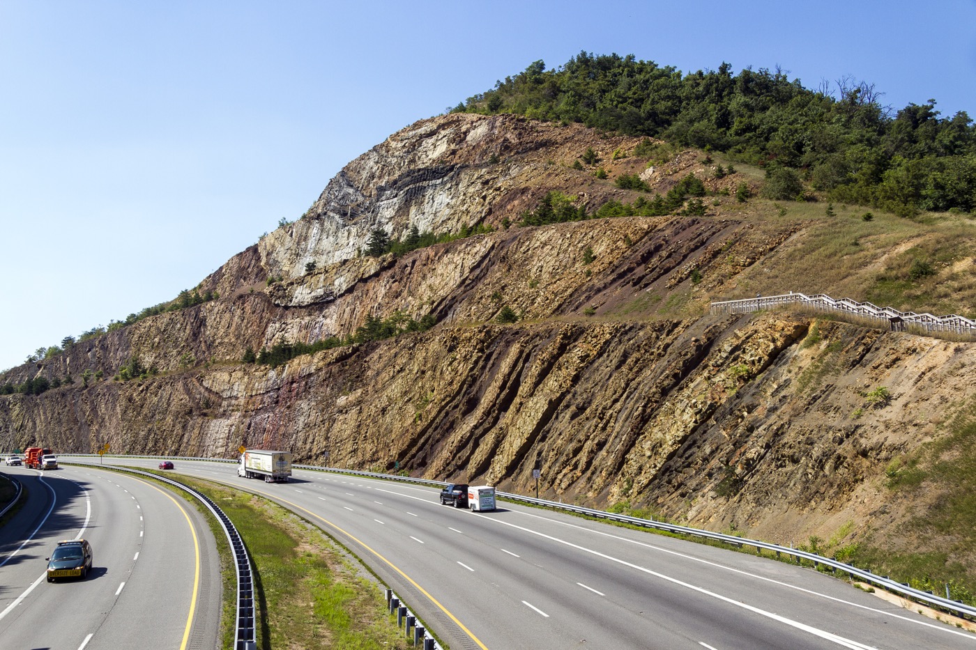
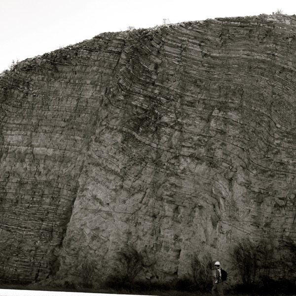
The Earth is an active planet shaped by dynamic forces. Such forces can build mountains and crumple and fold rocks. As rocks respond to these forces, they undergo deformation, which results in changes in shape and/or volume of the rocks. The resulting features are termed geologic structures. This deformation can produce dramatic and beautiful scenery, as evidenced in the figure of above, which shows the deformation of originally horizontal rock layers.
Why is it important to study deformation within the crust? Such studies can provide us with a record of the past and the forces that operated then. The correct interpretation of features created during deformation is critical in the petroleum and mining industry. It is also essential for engineering. Understanding the behavior of deformed rocks is necessary to create and maintain safe engineering structures. When proper geological planning is not considered in engineering, disasters can strike.
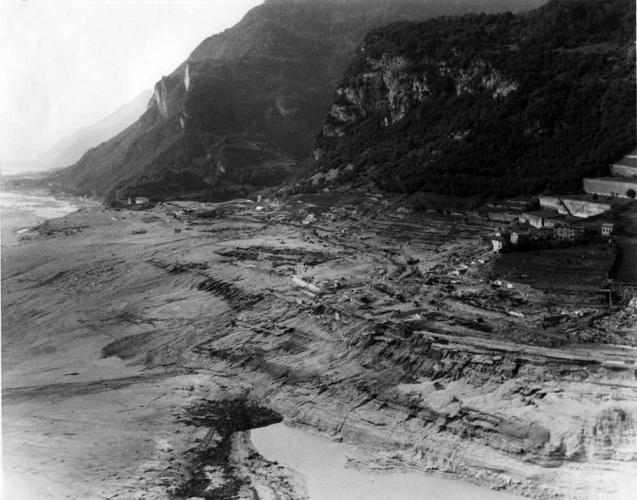
For example, the Vajont Dam was constructed at Monte Toc, Italy in the early 1960s. The site was a poor choice for a dam because the valley was narrow, thorough geological tests were not performed, and the area surrounding the dam was prone to large landslides. The steep canyon walls were composed of limestone with solution cavities, not known for its stability, and shifting and fracturing of rock that occurred during the filling of the reservoir was ignored.

In 1963, a massive landslide in the area displaced much of the water in the dam, causing it to override the top of the dam and flood the many villages downstream, resulting in the deaths of almost 2,000 people.
Select an image to view larger


Module Objectives
At the completion of this module you will be able to:
- Describe the types of stresses that exist within the Earth’s crust.
- Explain how rocks respond to those stresses by brittle, elastic, or plastic deformation, or by fracturing.
- Summarize how rocks become folded and know the terms used to describe the features of folds.
- Describe the conditions under which rocks fracture.
- Summarize the different types of faults, including normal, reverse, thrust, and strike-slip.
- Understand how measurements of strike and dip of a geological feature are determined.
Activities Overview
See the Schedule of Work for dates of availability and due dates.
Be sure to read through the directions for all of this module’s activities before getting started so that you can plan your time accordingly. You are expected to work on this course throughout the week.
Module 11 Assignment: Identifying Structural Features in a Geological Landscape
15 points
After you complete the reading, you can start working on Module 11 Assignment – Identifying Structural Features in a Geological Landscape
Module 11 Quiz
10 points
Module 11 Quiz has 10 multiple-choice questions and is based on the content of the Module 11 readings and Assignment 11.
The quiz is worth a total of 10 points (1 points per question). You will have only 10 minutes to complete the quiz, and you may take this quiz only once.
Note: that is not enough time to look up the answers!
Make sure that you fully understand all of the concepts presented and study for this quiz as though it were going to be proctored in a classroom, or you will likely find yourself running out of time.
Keep track of the time, and be sure to look over your full quiz results after you have submitted it for a grade.
Your Questions and Concerns…
Please contact me if you have any questions or concerns.
General course questions: If your question is of a general nature such that other students would benefit from the answer, then go to the discussions area and post it as a question thread in the “General course questions” discussion area.
Personal questions: If your question is personal, (e.g. regarding my comments to you specifically), then send me an email from within this course.
- Module 11: Structural Geology. Authored by: Anne Huth. Provided by: Pima Community College. Located at: http://cc.pima.edu/~lumen/glg101/module%20parts%20-%20LUMEN/Module11/L_Mod11.html. License: CC BY: Attribution
- Physical Geology, Adapted by Anne Huth, Pima Community College. Authored by: Steven Earle. Located at: https://opentextbc.ca/geology/. License: CC BY: Attribution
- Laboratory Manual for Introductory Geology, Adapted by Anne Huth, Pima Community College. Authored by: Bradley Deline, Randa Harris, and Karen Defend. Located at: https://open.umn.edu/opentextbooks/BookDetail.aspx?bookId=506. License: CC BY: Attribution
- Figure 1: Sideling Hill Cut. Authored by: Acroterion. Provided by: Wikimedia Commons. Located at: https://commons.wikimedia.org/wiki/File:Sideling_Hill_cut_MD1.jpg. License: CC BY-SA: Attribution-ShareAlike
- Figure 4: Sideling Hill Roadcut. Authored by: Jeff Kubina. Provided by: Flickr. Located at: https://www.flickr.com/photos/kubina/2083162931/in/album-72157603070983824/. License: CC BY-SA: Attribution-ShareAlike
- Figure 6: Milhook Cliffs. Authored by: Smalljim. Provided by: Wikimedia Commons. Located at: https://commons.wikimedia.org/wiki/File:Millook_cliffs_enh.jpg. License: CC BY: Attribution
- Figure 7: Migmatite_Rt58, Popple Hill, Fowler, NY. Authored by: Dave Spier. Provided by: Flickr. Located at: https://www.flickr.com/photos/dave_spier/9644530483. License: CC BY-NC-SA: Attribution-NonCommercial-ShareAlike
- Figure 8: Copper Creek Thrust Fault. Authored by: James St. John. Provided by: Flickr. Located at: https://www.flickr.com/photos/jsjgeology/36797756226. License: CC BY: Attribution
- Figure 9: Normal Faults, Highway 191 opposite Arches NP. Authored by: Roy Luck. Provided by: Flickr. Located at: https://www.flickr.com/photos/21550937@N03/6206249834/. License: CC BY: Attribution
- Figure 10: Reverse fault in Eagle Ford outcrop. Authored by: Roy Luck. Provided by: Flickr. Located at: https://www.flickr.com/photos/royluck/15566984365/in/photostream/. License: CC BY: Attribution
- Figure 2: Disastro Vajont. Authored by: unknown author. Provided by: Wikimedia Commons. Located at: https://commons.wikimedia.org/wiki/File:Disastro_Vajont.jpg. License: Public Domain: No Known Copyright
- Figure 5: Tectonic Folding. Authored by: R.J. Lillie, Parks and Plates. Provided by: National Park Service. Located at: https://www.nps.gov/articles/tectonic-folding.htm. License: Public Domain: No Known Copyright
- Figure 3: Vajont1963usarmy. Authored by: USGS Landslide Photo Collection. Provided by: Wikimedia Commons. Located at: https://commons.wikimedia.org/wiki/File:Vajont1963usarmy.jpg. License: Public Domain: No Known Copyright


