12.5: Geologic Structures Created by Plastic and Brittle Deformation
- Page ID
- 5677

\( \newcommand{\vecs}[1]{\overset { \scriptstyle \rightharpoonup} {\mathbf{#1}} } \)
\( \newcommand{\vecd}[1]{\overset{-\!-\!\rightharpoonup}{\vphantom{a}\smash {#1}}} \)
\( \newcommand{\dsum}{\displaystyle\sum\limits} \)
\( \newcommand{\dint}{\displaystyle\int\limits} \)
\( \newcommand{\dlim}{\displaystyle\lim\limits} \)
\( \newcommand{\id}{\mathrm{id}}\) \( \newcommand{\Span}{\mathrm{span}}\)
( \newcommand{\kernel}{\mathrm{null}\,}\) \( \newcommand{\range}{\mathrm{range}\,}\)
\( \newcommand{\RealPart}{\mathrm{Re}}\) \( \newcommand{\ImaginaryPart}{\mathrm{Im}}\)
\( \newcommand{\Argument}{\mathrm{Arg}}\) \( \newcommand{\norm}[1]{\| #1 \|}\)
\( \newcommand{\inner}[2]{\langle #1, #2 \rangle}\)
\( \newcommand{\Span}{\mathrm{span}}\)
\( \newcommand{\id}{\mathrm{id}}\)
\( \newcommand{\Span}{\mathrm{span}}\)
\( \newcommand{\kernel}{\mathrm{null}\,}\)
\( \newcommand{\range}{\mathrm{range}\,}\)
\( \newcommand{\RealPart}{\mathrm{Re}}\)
\( \newcommand{\ImaginaryPart}{\mathrm{Im}}\)
\( \newcommand{\Argument}{\mathrm{Arg}}\)
\( \newcommand{\norm}[1]{\| #1 \|}\)
\( \newcommand{\inner}[2]{\langle #1, #2 \rangle}\)
\( \newcommand{\Span}{\mathrm{span}}\) \( \newcommand{\AA}{\unicode[.8,0]{x212B}}\)
\( \newcommand{\vectorA}[1]{\vec{#1}} % arrow\)
\( \newcommand{\vectorAt}[1]{\vec{\text{#1}}} % arrow\)
\( \newcommand{\vectorB}[1]{\overset { \scriptstyle \rightharpoonup} {\mathbf{#1}} } \)
\( \newcommand{\vectorC}[1]{\textbf{#1}} \)
\( \newcommand{\vectorD}[1]{\overrightarrow{#1}} \)
\( \newcommand{\vectorDt}[1]{\overrightarrow{\text{#1}}} \)
\( \newcommand{\vectE}[1]{\overset{-\!-\!\rightharpoonup}{\vphantom{a}\smash{\mathbf {#1}}}} \)
\( \newcommand{\vecs}[1]{\overset { \scriptstyle \rightharpoonup} {\mathbf{#1}} } \)
\(\newcommand{\longvect}{\overrightarrow}\)
\( \newcommand{\vecd}[1]{\overset{-\!-\!\rightharpoonup}{\vphantom{a}\smash {#1}}} \)
\(\newcommand{\avec}{\mathbf a}\) \(\newcommand{\bvec}{\mathbf b}\) \(\newcommand{\cvec}{\mathbf c}\) \(\newcommand{\dvec}{\mathbf d}\) \(\newcommand{\dtil}{\widetilde{\mathbf d}}\) \(\newcommand{\evec}{\mathbf e}\) \(\newcommand{\fvec}{\mathbf f}\) \(\newcommand{\nvec}{\mathbf n}\) \(\newcommand{\pvec}{\mathbf p}\) \(\newcommand{\qvec}{\mathbf q}\) \(\newcommand{\svec}{\mathbf s}\) \(\newcommand{\tvec}{\mathbf t}\) \(\newcommand{\uvec}{\mathbf u}\) \(\newcommand{\vvec}{\mathbf v}\) \(\newcommand{\wvec}{\mathbf w}\) \(\newcommand{\xvec}{\mathbf x}\) \(\newcommand{\yvec}{\mathbf y}\) \(\newcommand{\zvec}{\mathbf z}\) \(\newcommand{\rvec}{\mathbf r}\) \(\newcommand{\mvec}{\mathbf m}\) \(\newcommand{\zerovec}{\mathbf 0}\) \(\newcommand{\onevec}{\mathbf 1}\) \(\newcommand{\real}{\mathbb R}\) \(\newcommand{\twovec}[2]{\left[\begin{array}{r}#1 \\ #2 \end{array}\right]}\) \(\newcommand{\ctwovec}[2]{\left[\begin{array}{c}#1 \\ #2 \end{array}\right]}\) \(\newcommand{\threevec}[3]{\left[\begin{array}{r}#1 \\ #2 \\ #3 \end{array}\right]}\) \(\newcommand{\cthreevec}[3]{\left[\begin{array}{c}#1 \\ #2 \\ #3 \end{array}\right]}\) \(\newcommand{\fourvec}[4]{\left[\begin{array}{r}#1 \\ #2 \\ #3 \\ #4 \end{array}\right]}\) \(\newcommand{\cfourvec}[4]{\left[\begin{array}{c}#1 \\ #2 \\ #3 \\ #4 \end{array}\right]}\) \(\newcommand{\fivevec}[5]{\left[\begin{array}{r}#1 \\ #2 \\ #3 \\ #4 \\ #5 \\ \end{array}\right]}\) \(\newcommand{\cfivevec}[5]{\left[\begin{array}{c}#1 \\ #2 \\ #3 \\ #4 \\ #5 \\ \end{array}\right]}\) \(\newcommand{\mattwo}[4]{\left[\begin{array}{rr}#1 \amp #2 \\ #3 \amp #4 \\ \end{array}\right]}\) \(\newcommand{\laspan}[1]{\text{Span}\{#1\}}\) \(\newcommand{\bcal}{\cal B}\) \(\newcommand{\ccal}{\cal C}\) \(\newcommand{\scal}{\cal S}\) \(\newcommand{\wcal}{\cal W}\) \(\newcommand{\ecal}{\cal E}\) \(\newcommand{\coords}[2]{\left\{#1\right\}_{#2}}\) \(\newcommand{\gray}[1]{\color{gray}{#1}}\) \(\newcommand{\lgray}[1]{\color{lightgray}{#1}}\) \(\newcommand{\rank}{\operatorname{rank}}\) \(\newcommand{\row}{\text{Row}}\) \(\newcommand{\col}{\text{Col}}\) \(\renewcommand{\row}{\text{Row}}\) \(\newcommand{\nul}{\text{Nul}}\) \(\newcommand{\var}{\text{Var}}\) \(\newcommand{\corr}{\text{corr}}\) \(\newcommand{\len}[1]{\left|#1\right|}\) \(\newcommand{\bbar}{\overline{\bvec}}\) \(\newcommand{\bhat}{\widehat{\bvec}}\) \(\newcommand{\bperp}{\bvec^\perp}\) \(\newcommand{\xhat}{\widehat{\xvec}}\) \(\newcommand{\vhat}{\widehat{\vvec}}\) \(\newcommand{\uhat}{\widehat{\uvec}}\) \(\newcommand{\what}{\widehat{\wvec}}\) \(\newcommand{\Sighat}{\widehat{\Sigma}}\) \(\newcommand{\lt}{<}\) \(\newcommand{\gt}{>}\) \(\newcommand{\amp}{&}\) \(\definecolor{fillinmathshade}{gray}{0.9}\)Folds
Folds are geologic structures created by plastic deformation of the Earth’s crust. To understand how folds are generated, take a piece of paper and hold it up with a hand on each end. Apply compressional forces (push the ends towards each other). You have just created a fold (bent rock layers). Depending on how your paper moved, you created one of the three main fold types (Figure 12.11).
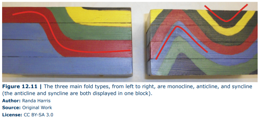
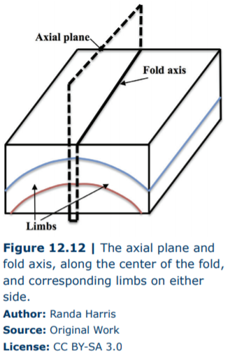
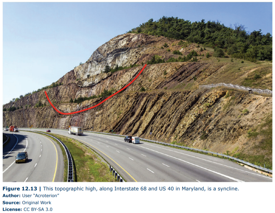
A monocline is a simple fold structure that consists of a bend in otherwise horizontal rock layers. More commonly found are anticlines and synclines. An anticline fold is convex up and one in which the layered strata are inclined down and away from the center of the fold (if you drew a line across it, the anticline would resemble a capital letter A). A syncline is a concave upward fold in which the layered strata are inclined up (it resembles a smile). Parts of a fold include the axis (the hinge line), the axial plane, and limbs on either side of the axis (Figure 12.12). It is important to note that anticlines do not always represent mountains or high areas and synclines do not always represent basins or low areas. They are simply folded rock layers and do not necessarily indicate topographic high and low points (see Figure 12.13).
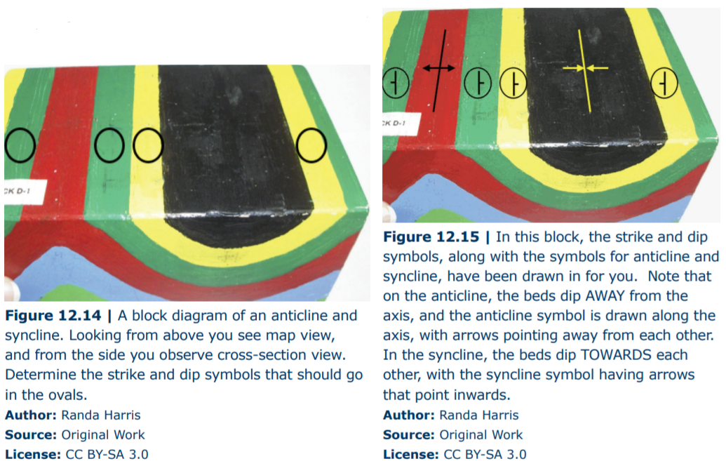
Folds observed in cross-section look much different from the map view. In map view, rather than seeing folds, you will only encounter beds that look like Figure 12.14. To help determine what type of fold you have, it is useful to determine the strike and dip of the beds you encounter. In Figure 12.14, determine the strike and dip for each location marked by an oval. Check yourself against Figure 12.15.
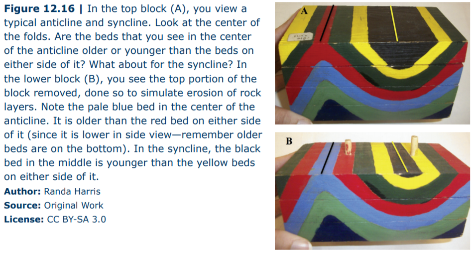
Once rocks are folded and exposed at the Earth’s surface, they are subjected to erosion, creating regular patterns. The erosion exposes the interiors of the folds, such that parallel bands of dipping strata can be observed along the fold axis. In an anticline, the oldest rocks are exposed along the fold axis, while it is the youngest rocks exposed at the fold axis in a syncline (Figure 12.16)
| Fold Type | Direction of Dip of Layers | Age of Beds at Axis |
| Anticline | Away from axis | Oldest |
| Syncline | Towards the axis | Youngest |
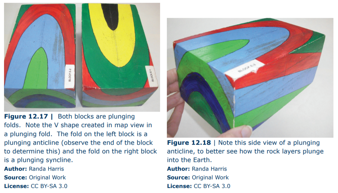
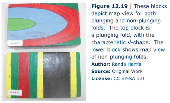
Imagine you take that same sheet of paper that you originally created a fold with. Create a fold again, but rather than holding it horizontally, plunge one end of your paper down into your desk surface. You have now created a plunging fold, which is essentially a tilted fold that creates a V-shaped pattern on the surface (Figures 12.17, 12.18, and 12.19). In an anticline, the oldest strata can be found at the center of the V, and the V points in the direction of the plunge of the fold axis. In a syncline, the youngest strata are found at the center of the V, and the V points in the opposite direction of the plunge of the fold axis.
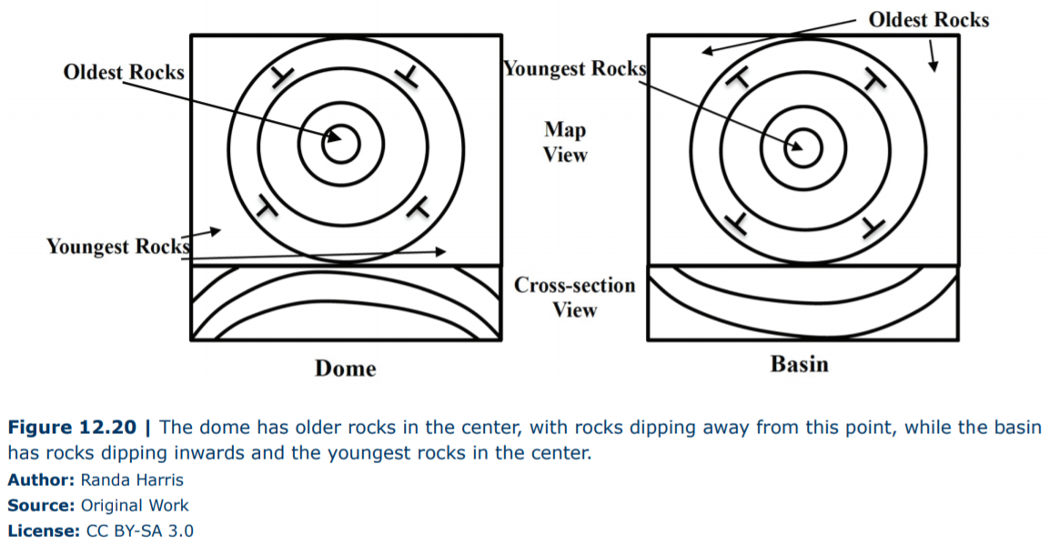
Similar to anticlines and synclines are domes and basins, which are basically the circular (or elliptical) equivalent of those folds. A dome is an upfold similar to an anticline, and a basin is an area where the rocks are inclined downward towards the center, similar to a syncline (Figure 12.20). The key to identifying these structures is similar to identifying the folds. In a dome, the oldest rocks are exposed at the center, and rocks dip away from this central point. In a basin, the youngest rocks are in the center, and the rocks dip inward towards the center.
Faults
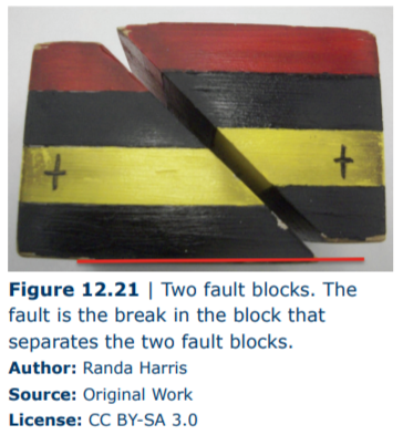 As rocks undergo brittle deformation, they may produce cracks in the rocks. If no appreciable displacement has occurred along these cracks, they are called joints. If appreciable displacement does occur, they are referred to as faults. We will first examine dip-slip faults, in which the movement along the fault is either up or down. The two masses of rock that are cut by a fault are termed the fault blocks (Figure 12.21). The type of fault is determined by the direction that the fault blocks have moved.
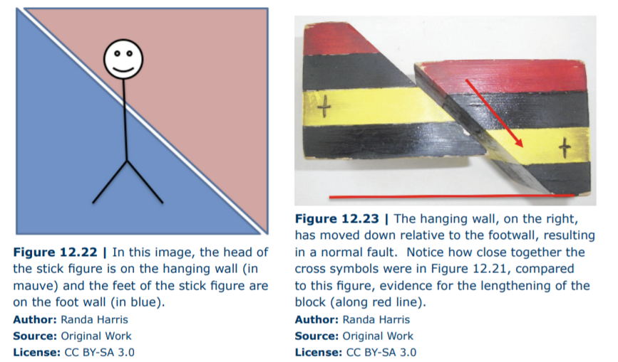
Fault block movement is described based on the movement of the hanging wall, the fault block located above the fault plane. The other fault block, located beneath the fault plane, is called the foot wall. The term hanging wall comes from the idea that if a miner was climbing along the fault plane, she would hang her lantern above her head, along the hanging wall. Alternately, you can draw a stick figure straight up and down across the fault plane. Its head will be on the hanging wall and its feet will be on the footwall (Figure 12.22).
When extensional forces are applied to the fault blocks, the hanging wall will move down, creating what is called a normal fault (an easy way to remember this is the phrase “It’s normal to fall down”). As this happens, the crust is stretched out and lengthened (Figure 12.23).
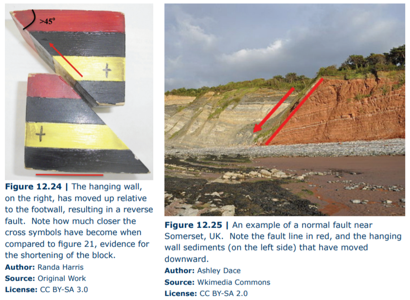
When compressional forces are applied to the fault blocks, the hanging wall will move up, creating a reverse fault. This causes the crust to shorten in the area (Figure 12.24). A special type of reverse fault is a thrust fault. It is a low angle reverse fault (with a dip angle of less than 45o), and has a much thinner hanging wall.
| Fault Type | Type of Force | Direction HW Moved | Length of Block |
| Normal | Extensional | Down | Lengthened |
| Reverse | Compressional | Up | Shortened |
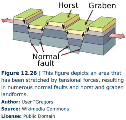
Tensional forces acting over a region can produce normal faults that result in landforms known as horst and grabens. In horst and grabens, the graben is the crustal block that downdrops, and is surrounded by two horsts, the relatively uplifted crustal blocks (Figure 12.26). This terrain is typical of the Basin and Range of the western United States.
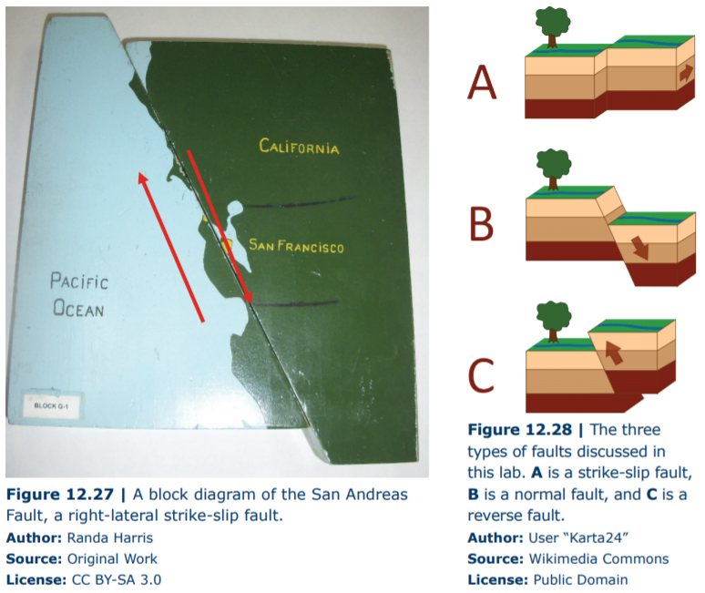
The previous faults we observed were dip-slip faults, where movement occurred parallel with the fault’s dip. In a strike-slip fault, horizontal motion occurs (in the direction of strike, hence the name), with blocks on opposite sides of a fault sliding past each other due to shear forces. The classic example of a strike-slip fault is the San Andreas Fault in California (Figure 12.27). These faults can be furthered classified as right-lateral or left-lateral. To determine this, an observer would stand along one side of the fault, looking across at the opposite fault block. If that fault block appears to have moved right, it is right-lateral; if it has moved left, it is left-lateral. Figure 12.28 provides all three fault types for your review.