

7.3.1: Folding and Faulting
- Page ID
- 42677

\( \newcommand{\vecs}[1]{\overset { \scriptstyle \rightharpoonup} {\mathbf{#1}} } \)
\( \newcommand{\vecd}[1]{\overset{-\!-\!\rightharpoonup}{\vphantom{a}\smash {#1}}} \)
\( \newcommand{\dsum}{\displaystyle\sum\limits} \)
\( \newcommand{\dint}{\displaystyle\int\limits} \)
\( \newcommand{\dlim}{\displaystyle\lim\limits} \)
\( \newcommand{\id}{\mathrm{id}}\) \( \newcommand{\Span}{\mathrm{span}}\)
( \newcommand{\kernel}{\mathrm{null}\,}\) \( \newcommand{\range}{\mathrm{range}\,}\)
\( \newcommand{\RealPart}{\mathrm{Re}}\) \( \newcommand{\ImaginaryPart}{\mathrm{Im}}\)
\( \newcommand{\Argument}{\mathrm{Arg}}\) \( \newcommand{\norm}[1]{\| #1 \|}\)
\( \newcommand{\inner}[2]{\langle #1, #2 \rangle}\)
\( \newcommand{\Span}{\mathrm{span}}\)
\( \newcommand{\id}{\mathrm{id}}\)
\( \newcommand{\Span}{\mathrm{span}}\)
\( \newcommand{\kernel}{\mathrm{null}\,}\)
\( \newcommand{\range}{\mathrm{range}\,}\)
\( \newcommand{\RealPart}{\mathrm{Re}}\)
\( \newcommand{\ImaginaryPart}{\mathrm{Im}}\)
\( \newcommand{\Argument}{\mathrm{Arg}}\)
\( \newcommand{\norm}[1]{\| #1 \|}\)
\( \newcommand{\inner}[2]{\langle #1, #2 \rangle}\)
\( \newcommand{\Span}{\mathrm{span}}\) \( \newcommand{\AA}{\unicode[.8,0]{x212B}}\)
\( \newcommand{\vectorA}[1]{\vec{#1}} % arrow\)
\( \newcommand{\vectorAt}[1]{\vec{\text{#1}}} % arrow\)
\( \newcommand{\vectorB}[1]{\overset { \scriptstyle \rightharpoonup} {\mathbf{#1}} } \)
\( \newcommand{\vectorC}[1]{\textbf{#1}} \)
\( \newcommand{\vectorD}[1]{\overrightarrow{#1}} \)
\( \newcommand{\vectorDt}[1]{\overrightarrow{\text{#1}}} \)
\( \newcommand{\vectE}[1]{\overset{-\!-\!\rightharpoonup}{\vphantom{a}\smash{\mathbf {#1}}}} \)
\( \newcommand{\vecs}[1]{\overset { \scriptstyle \rightharpoonup} {\mathbf{#1}} } \)
\(\newcommand{\longvect}{\overrightarrow}\)
\( \newcommand{\vecd}[1]{\overset{-\!-\!\rightharpoonup}{\vphantom{a}\smash {#1}}} \)
\(\newcommand{\ket}[1]{\left| #1 \right>}\)
\(\newcommand{\bra}[1]{\left< #1 \right|}\)
\(\newcommand{\braket}[2]{\left< #1 \vphantom{#2} \right| \left. #2 \vphantom{#1} \right>}\)
\(\newcommand{\braopket}[3]{\left< #1 \vphantom{#2}\vphantom{#3} \right| #2 \vphantom{#1}\vphantom{#3} \left| #3 \vphantom{#1}\vphantom{#2} \right>}\)
\(\newcommand{\qmvec}[1]{\mathbf{\vec{#1}}}\)
\(\newcommand{\op}[1]{\hat{\mathbf{#1}}}\)
\(\newcommand{\expect}[1]{\langle #1 \rangle}\)
\(\newcommand{\dfn}[1]{\emph{\textbf{#1}}}\)
Folding
When rocks deform by plastic deformation they can bend and fold. The process of folding occurs when rock is compressed, as it is along colliding plate boundaries. Upturned folds are called anticlines and down turned folds are called synclines . Anticlines and synclines are geologic structures, that is, they are folds in rock material. They give expression to the surface as linear ridges (anticlines) and troughs (synclines). The sides of the fold are called the limbs. Each fold has an axial plane, an imaginary plane that runs down its length and divides the fold in half.
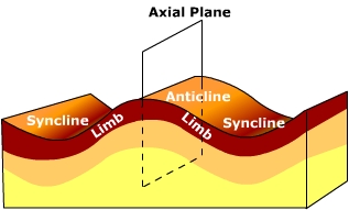
Figure \(\PageIndex{1}\) is a three-dimensional block model showing a folded sequence of rock layers. The layers form a wave-like pattern with alternating upward arches and downward troughs.
The central upward fold is labeled anticline. An anticline is an arch-shaped fold in which the rock layers bend upward. On either side of the anticline are downward-curving folds labeled syncline. A syncline is a trough-shaped fold in which the rock layers bend downward.
The sloping sides of the fold are labeled limbs. The limbs connect the crest of the anticline to the adjacent synclines and represent the portions of the rock layers that dip away from the fold crest.
A vertical surface passing through the center of the anticline is labeled axial plane. This imaginary plane divides the fold into two roughly symmetrical halves and marks the center of the fold structure.
The colored rock layers remain continuous throughout the folded structure, demonstrating that the rocks were bent rather than broken.
The diagram illustrates how rock layers deform under compressional stress, causing them to fold into anticlines and synclines rather than fracture. Anticlines and synclines are common features in mountain belts and are evidence of crustal compression associated with tectonic plate interactions. The figure identifies the main parts of a fold—anticline, syncline, limbs, and axial plane—and shows how geologists describe folded rock structures.
Symmetrical or open folds with their near-vertical axial planes and gently dipping limbs of about the same angle are a product of gentle compression. Symmetrical folds are found near the margins of mountain systems where tectonic activity is relatively quiet. If the compression is more pronounced from one direction, an overturned fold may occur. Extreme directed pressure may lay the fold over with its axial plane nearly horizontal with the surface producing a recumbent fold. Sometimes the length of the folds are tilted creating plunging folds. One of the best examples of folded topography is the Appalachian mountains found in the Ridge and Valley physiographic province of North America.

Figure \(\PageIndex{2}\) captures a classic geological anticline, which is a fold in the Earth's crust that curves upward into an arch-like shape. In this structural arrangement, the oldest rock layers are found at the center of the fold. This particular outcrop in the Stellarton Formation of New Glasgow, Nova Scotia, serves as a clear visual record of how immense compressive forces from moving tectonic plates can slowly warp and bend solid sedimentary rock over millions of years.
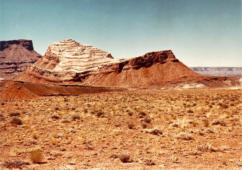
Figure \(\PageIndex{3}\) is a photograph that depicts the Rainbow Basin Syncline, a prominent geological fold located near Barstow, California. The image shows a desert landscape where sedimentary rock layers have been compressed into a distinct U-shaped or bowl-like curve. These layers, which belong to the Barstow Formation, display varying colors and textures, clearly highlighting the downward-arching structure of the syncline. The erosion of the surrounding terrain reveals the internal sequence of the strata, with the youngest rock layers located at the center of the fold.
Faulting
When enormous stresses build and push large intact rock masses beyond their yield limit, faulting of the surface is likely to occur. A fault is a fracture along which movement occurs. The plane that extends into the earth and along which slippage occurs is called the fault plane. The fault dip is the angle from horizontal that the fault plane makes. The map direction that the fault takes is called the strike, measured east or west of true north. Generally, two walls are distinguished: the footwall and hanging wall. The hanging wall moves horizontally, vertically, or in both directions relative to the footwall. We identify the hanging and foot walls relative to the fault plane. The hanging wall is above the fault plane, while the foot wall is below. The steep face of an exposed block is called the fault scarp. The fault line is the trace of the fault along the surface.
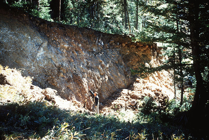
Faults can be traced for thousands of kilometers across the surface at tens of kilometers in depth. The sudden slippage of rock masses past one another results in shock waves that we feel as an earthquake.
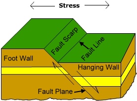
Figure \(\PageIndex{5}\) is a three-dimensional block model showing a fault, a fracture in rock along which movement has occurred due to stress.
At the top of the figure, arrows labeled Stress point away from each other in opposite directions, indicating that the crust is being pulled apart by tensional stress.
A diagonal surface cutting through the rock block is labeled the fault plane. This is the surface along which movement occurs.
The line where the fault plane intersects Earth's surface is labeled the fault line. The exposed face of the fault at the surface is labeled the fault scarp, a step-like feature created by displacement along the fault.
The block of rock located above the fault plane is labeled the hanging wall. The block below the fault plane is labeled the footwall.
The hanging wall has moved downward relative to the footwall, creating an offset in the rock layers visible within the block. The same light-colored rock layer appears lower on the hanging wall side than on the footwall side.
The diagram illustrates a normal fault, which forms when Earth's crust is stretched by tensional forces. As the crust pulls apart, the hanging wall drops downward relative to the footwall along the fault plane. Normal faults are common in regions where the crust is extending, such as continental rift zones. The figure identifies the key components of a fault—fault plane, fault line, fault scarp, hanging wall, and footwall—and shows how rock layers become displaced during fault movement.