

3.1.7.1: The Radiation Balance
- Page ID
- 40025

\( \newcommand{\vecs}[1]{\overset { \scriptstyle \rightharpoonup} {\mathbf{#1}} } \)
\( \newcommand{\vecd}[1]{\overset{-\!-\!\rightharpoonup}{\vphantom{a}\smash {#1}}} \)
\( \newcommand{\dsum}{\displaystyle\sum\limits} \)
\( \newcommand{\dint}{\displaystyle\int\limits} \)
\( \newcommand{\dlim}{\displaystyle\lim\limits} \)
\( \newcommand{\id}{\mathrm{id}}\) \( \newcommand{\Span}{\mathrm{span}}\)
( \newcommand{\kernel}{\mathrm{null}\,}\) \( \newcommand{\range}{\mathrm{range}\,}\)
\( \newcommand{\RealPart}{\mathrm{Re}}\) \( \newcommand{\ImaginaryPart}{\mathrm{Im}}\)
\( \newcommand{\Argument}{\mathrm{Arg}}\) \( \newcommand{\norm}[1]{\| #1 \|}\)
\( \newcommand{\inner}[2]{\langle #1, #2 \rangle}\)
\( \newcommand{\Span}{\mathrm{span}}\)
\( \newcommand{\id}{\mathrm{id}}\)
\( \newcommand{\Span}{\mathrm{span}}\)
\( \newcommand{\kernel}{\mathrm{null}\,}\)
\( \newcommand{\range}{\mathrm{range}\,}\)
\( \newcommand{\RealPart}{\mathrm{Re}}\)
\( \newcommand{\ImaginaryPart}{\mathrm{Im}}\)
\( \newcommand{\Argument}{\mathrm{Arg}}\)
\( \newcommand{\norm}[1]{\| #1 \|}\)
\( \newcommand{\inner}[2]{\langle #1, #2 \rangle}\)
\( \newcommand{\Span}{\mathrm{span}}\) \( \newcommand{\AA}{\unicode[.8,0]{x212B}}\)
\( \newcommand{\vectorA}[1]{\vec{#1}} % arrow\)
\( \newcommand{\vectorAt}[1]{\vec{\text{#1}}} % arrow\)
\( \newcommand{\vectorB}[1]{\overset { \scriptstyle \rightharpoonup} {\mathbf{#1}} } \)
\( \newcommand{\vectorC}[1]{\textbf{#1}} \)
\( \newcommand{\vectorD}[1]{\overrightarrow{#1}} \)
\( \newcommand{\vectorDt}[1]{\overrightarrow{\text{#1}}} \)
\( \newcommand{\vectE}[1]{\overset{-\!-\!\rightharpoonup}{\vphantom{a}\smash{\mathbf {#1}}}} \)
\( \newcommand{\vecs}[1]{\overset { \scriptstyle \rightharpoonup} {\mathbf{#1}} } \)
\(\newcommand{\longvect}{\overrightarrow}\)
\( \newcommand{\vecd}[1]{\overset{-\!-\!\rightharpoonup}{\vphantom{a}\smash {#1}}} \)
\(\newcommand{\ket}[1]{\left| #1 \right>}\)
\(\newcommand{\bra}[1]{\left< #1 \right|}\)
\(\newcommand{\braket}[2]{\left< #1 \vphantom{#2} \right| \left. #2 \vphantom{#1} \right>}\)
\(\newcommand{\braopket}[3]{\left< #1 \vphantom{#2}\vphantom{#3} \right| #2 \vphantom{#1}\vphantom{#3} \left| #3 \vphantom{#1}\vphantom{#2} \right>}\)
\(\newcommand{\qmvec}[1]{\mathbf{\vec{#1}}}\)
\(\newcommand{\op}[1]{\hat{\mathbf{#1}}}\)
\(\newcommand{\expect}[1]{\langle #1 \rangle}\)
\(\newcommand{\dfn}[1]{\emph{\textbf{#1}}}\)
Shortwave radiation
The radiation balance of the Earth system is an accounting of the incoming and outgoing components of radiation. These components are balanced over long time periods and over the Earth as whole. If they weren't the Earth would be continually cooling or warming. However, over a short period of time, radiant energy is unequally distributed over the Earth.
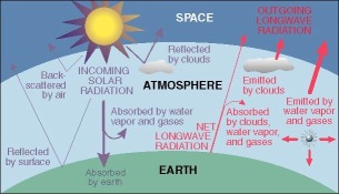
Figure \(\PageIndex{1}\) illustrates the Earth's radiation balance—an accounting system for the incoming solar energy (shortwave radiation) and the outgoing heat energy (long wave radiation). The diagram shows that the Earth system (atmosphere and surface combined) maintains equilibrium:
-
Incoming Energy (Shortwave): 100% of solar radiation enters the system. About 30% is reflected back to space by clouds, aerosols, and the surface (albedo), while the remaining 70% is absorbed by the atmosphere (20%) and the surface (50%).
-
Outgoing Energy (Long wave): This 70% absorbed energy is ultimately radiated back to space as long wave (thermal) radiation. This is primarily done through direct emission from the surface, emission from the atmosphere (including gases and clouds), and transfer mechanisms like latent heat (evaporation) and sensible heat.
The figure demonstrates that for Earth's temperature to remain stable over time, the total energy reflected (30%) plus the total heat radiated to space (70%) must perfectly balance the 100% of incoming solar radiation.
The radiation balance of the Earth system is depicted in the Figure \(\PageIndex{1}\) (Shortwave radiation is colored purple and long wave radiation is in red.) Shortwave radiation from the Sun penetrates through space to the outer edge of the atmosphere unimpeded by the vacuum of outer space. Once solar radiation begins to penetrate through the atmosphere this amount begins to decrease due to absorption and reflection.
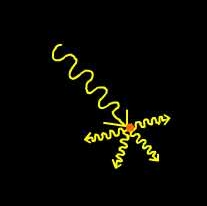
Figure \(\PageIndex{2}\) shows how incoming solar radiation interacts with particles or molecules in the atmosphere.
A wavy line enters from one direction and represents incoming electromagnetic radiation carrying energy toward a particle. At the point where the incoming radiation meets the particle, the path changes.
After this interaction, several shorter wavy lines extend outward in multiple different directions from the same point. These outgoing waves represent energy being redistributed rather than continuing in a straight path.
This pattern shows that the original incoming radiation has been scattered by the particle. Instead of traveling in a single direction, the energy is redirected in many directions.
The diagram illustrates the process of scattering, where atmospheric particles alter the path of radiation. This reduces the intensity of radiation traveling directly in one direction and spreads the energy across multiple directions. This process explains why radiation can be diffused and why not all incoming solar energy reaches the surface in a straight line.
About 30% of the available solar radiation at the top of the atmosphere is reflected or scattered back to space by particulates and clouds before it reaches the ground. The gases of the atmosphere are relatively poor absorbers of solar radiation, absorbing only about 20% of what is available at the outer edge of the atmosphere. The remaining solar radiation makes its way to surface as direct and diffuse solar radiation. Direct solar radiation (S) is shortwave radiation able to penetrate through the atmosphere without having been affected by constituents of the atmosphere in any way. Diffuse radiation (D) is shortwave radiation that has been scattered by gases in the atmosphere. Scattering is a process whereby a beam of radiation is broken down into many weaker rays redirected in other directions. Together, direct and diffuse shortwave radiation accounts for the total incoming solar radiation or insolation (K↓). In equation form:
K↓ = S+D
The fate of incoming solar radiation that reaches the Earth's surface is split between absorption and reflection. The albedo of a surface quantifies this reflection, representing the proportion of light bounced away, ranging from 0 (no reflection) to 1 (complete reflection). This value is often expressed as a percentage. Table \(\PageIndex{1}\) shows the sample albedos for different surfaces. For instance, highly reflective surfaces like fresh snow have a high albedo (upwards of 87%), whereas typical grass reflects about 23% (0.23). Surface characteristics like color and texture significantly influence this value. Dark surfaces absorb more: fresh asphalt has a low albedo (0.04), which is why it absorbs more than worn, lighter-colored asphalt (0.12). Similarly, a dark coniferous forest (0.08) absorbs more heat than lighter bare soil (0.17), while new concrete reflects a significant portion due to its light color (0.55).
|
Surface |
Typical Albedo |
|---|---|
|
Fresh asphalt |
0.04 |
|
Worn Asphalt |
0.12 |
|
Bare Soil |
0.17 |
|
Conifer forest |
0.08 |
|
Green Grass |
0.25 |
|
New Concrete |
0.55 |
|
Fresh Snow |
0.80 - 0.90 |
The amount of reflection (K↑) is given by the following equation:
K↑ = (S+D)a
The amount of reflection basically depends on the color of the surface, darker surfaces reflect less than lighter colored ones. For some surfaces, like water, the sun angle affects albedo. If you have been out on a lake during the day you might have noticed that the sun reflects off the surface more when the sun is lower in the sky than it does when it is more directly overhead.
Net shortwave radiation is the difference between incoming and outgoing shortwave radiation expressed as:
K*= (S+D) - (S+D)a
During the day, K* is a positive value as incoming always exceeds outgoing shortwave radiation. At night, K* is equal to zero as the Sun is below the horizon. (No, moonlight doesn't count!)
The Urban Heat Island (UHI) effect illustrated in Figure \(\PageIndex{3}\) explains why cities are noticeably warmer than the surrounding rural areas. This phenomenon is caused because the materials that dominate urban environments—such as dark asphalt roads and rooftops—have a very low albedo, meaning they absorb a large percentage of incoming sunlight and convert it into heat . For instance, fresh asphalt absorbs $96\%$ of solar radiation, whereas a lighter surface like new concrete absorbs only $45\%$. These dense, hard surfaces lack the cooling effects provided by natural processes like evapotranspiration from vegetation (which is high in rural areas). Consequently, cities act like massive thermal batteries, storing vast amounts of heat during the day and slowly releasing it at night, maintaining consistently higher temperatures.

Figure \(\PageIndex{3}\) shows a street scene with buildings, trees, and different types of roof surfaces labeled with their reflectivity values, which indicate how much incoming solar radiation each surface reflects.
In the foreground, a road runs through the center of the image, with buildings on both sides. Trees and vegetation are also shown along the street.
On the left side, a roof is labeled “Highly Reflective Roof” with a reflectivity value of approximately 0.60 to 0.70. This indicates that this surface reflects a large portion of incoming solar radiation and absorbs less heat.
Nearby, a “Corrugated Roof” is labeled with a reflectivity value of about 0.10 to 0.15, meaning it reflects less radiation and absorbs more heat compared to the highly reflective roof.
In the center, a building with “Colored Paint” is labeled with a reflectivity range of about 0.15 to 0.35. Another building with “White Paint” is labeled with a higher reflectivity range of about 0.50 to 0.90, showing that lighter-colored surfaces reflect more radiation than darker or colored surfaces.
On the right side, two additional roof types are shown:
- “Tar and Gravel Roof” with a reflectivity of about 0.03 to 0.18, indicating low reflectivity and high heat absorption.
- “Red/Brown Tile Roof” with reflectivity values of about 0.10 to 0.35, showing moderate reflection.
The diagram demonstrates how different building materials and surface colors affect the amount of solar radiation reflected versus absorbed. Surfaces with higher reflectivity reflect more energy and stay cooler, while surfaces with lower reflectivity absorb more energy and become warmer. This illustrates how urban materials influence local temperature and energy balance.
Long wave radiation
The energy absorbed by the surface is radiated from the Earth as terrestrial long wave radiation (L↑). The amount of energy emitted is primarily dependent on the temperature of the surface. The hotter the surface the more radiant energy it will emit. The gases of the atmosphere are relatively good absorbers of long wave radiation and thus absorb the energy emitted by the surface. The absorbed radiation is emitted in all directions with the downward directed portion being long wave atmospheric counter-radiation (L↓).
The difference between incoming and outgoing long wave radiation is net long wave radiation expressed as:
L* = L↓ - L↑
Recall that under normal conditions air temperature decreases with an increase in altitude through the troposphere. This occurs because the earth is the immediate source of energy for heating the air above it. Knowing that heat is transferred from warmer to cooler bodies, this means the surface is normally hotter than the air above. So for most situations, net long wave radiation is a negative value as more long wave radiation is emitted by the Earth than it gains from the air. Some of this radiation is emitted out to space is lost from the earth system. That which is not lost to space is absorbed by the atmosphere and drives the "greenhouse" effect.
Under other circumstances net long wave can be zero or a positive number. If zero the amount of radiation emitted by the surface would be equal to that of the air. This is true when the air and surface have the same temperature. If the air is warmer than the ground a positive value exists. This could occur with heavy cloud cover (clouds are good absorbers and radiators of long wave radiation) or if a warm air mass travels over a colder surface.
Net Radiation
Net Radiation is the difference between incoming (i.e., S and L↓) and outgoing components of radiation (S+D)a and L↑.
Q*= [(S+D) - (S+D)a] + L↓ - L↑
Net radiation can be positive, negative, or zero. Net radiation is positive when there is more incoming radiation than outgoing radiation. This typically occurs during the day time when the sun is out and the air temperature is the warmest. At night, net radiation is usually a negative value as there is no incoming solar radiation and net long wave is dominated by the outgoing terrestrial long wave flux. Net radiation is zero when the incoming and outgoing components are in perfect balance, which doesn't occur too often.
A net radiometer measures incoming and outgoing radiation from an alpine snow pack. Measurements such as this aid in determining snow melt and the availability of water to fill community reservoirs like those near Boulder, CO.
Understanding net radiation and its distribution is fundamental to explaining many geographical patterns of the components of the earth system. Net radiation is the radiant energy that is available to do work within the earth system. This work is manifested in a variety of ways, from heating the air, to warming the surface, to causing water to evaporate.