
16.4: Important Kinds of Climbing-Bed-Form Cross Stratification
- Page ID
- 4256

Introduction
Here I will present the substance of what the major kinds of cross stratification in the sedimentary record look like. They conveniently fall into (1) unidirectional-flow cross stratification, on a small scale corresponding to ripples and on a larger scale corresponding to dunes, and (2) oscillatory-flow cross stratification. Unfortunately there is little I can say at present about combined-flow cross stratification. I will make a few comments about that in the section on oscillatory-flow cross stratification.
Small-Scale Cross Stratification in Unidirectional Flow
Small-scale cross stratification formed under unidirectional flow is associated almost entirely with the downstream movement of current ripples. In accordance with the discussion of how moving bed forms produce cross-stratified deposits, discussed above, the general features of the cross stratification geometry depend on
- The geometry of the ripples themselves, as well as how that geometry changes with time as the ripples move, and
- The angle of climb.
For small angles of climb, the general geometry of the cross-stratified deposit is shown by the block diagram in Figure \(\PageIndex{1}\). In addition to the actual rippled surface, Figure \(\PageIndex{1}\) shows a flow-parallel section and a flow-transverse section perpendicular to the overall bedding. Figure \(\PageIndex{1}\) is the real-life counterpart of Figure 16.3.8.
In sections parallel to flow (Figure \(\PageIndex{1}\)) you see sets of laminae dipping mostly or entirely in the same direction (which is the flow direction), separated by truncation surfaces. The height of the sets is seldom greater than \(2–3\) \(\mathrm{cm}\), because it is always some fraction of the ripple height, which itself is seldom greater than \(2–3\) \(\mathrm{cm}\). The set boundaries are sinuous and irregular, because of the changes in the ripples as they move. Sets are commonly cut out at some point in the downstream direction by the overlying truncation surface. This is a reflection of either (1) locally stronger erosion by a passing ripple trough or (2) disappearance of a given ripple as it moved downstream, by being overtaken or absorbed by another faster-moving ripple from upstream. New sets also appear in the downstream direction, reflecting the birth of a new ripple in the train of ripples.
In sections transverse to flow, the geometry of cross stratification is rather different (Figure \(\PageIndex{1}\)): you see nested and interleaved sets whose lateral dimensions are usually less than something like five times the vertical dimension. Each set is truncated by one or more truncation surfaces. These truncation surfaces are mostly concave upward. The laminae within each set are also mostly concave upward, but the truncation surfaces generally cut the laminae discordantly.
The key to understanding this cross-stratification geometry lies in the geometry of ripple troughs and the trough-filling process. Recall from Chapter 12 that fully developed current ripples have strongly three-dimensional geometry, and an important element of that three-dimensional geometry is the existence of locally much deeper hollows or swales or depressions in ripple troughs, where the separated flow happens to become concentrated (because of the details of the ripple geometry upstream) and where scour or erosion is much stronger. As one of these swales shifts downstream, driven by the advancing ripple upstream, it carves a rounded furrow or trench, oriented parallel to the flow, which is then filled with scoop-shaped or spoon-shaped laminae that are the foreset deposits of the upstream ripple. Eventually the resulting set of laminae is partly or mostly or even entirely eroded by the passage of a locally deeper swale in some later ripple trough. This accounts for both the geometry of the sets and their irregular interleaving.
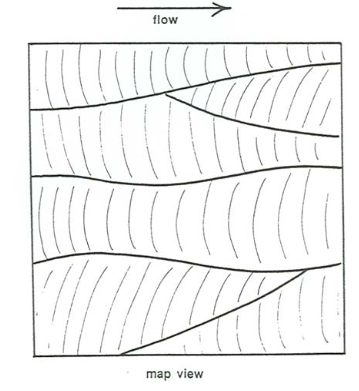
On the rare occasions when you are able to see a planar section through the deposit parallel to the overall stratification, you see a geometry that looks like Figure \(\PageIndex{2}\), which shows the truncated edges of sets of laminae that are strongly concave downstream, separated laterally by truncation surfaces. This has been called rib and furrow (not a very descriptive term). It is an excellent paleocurrent indicator.
For large angles of climb, the general geometry of the cross-stratified deposit is shown by the block diagram in Figure \(\PageIndex{3}\). In addition to the actual rippled surface, Figure \(\PageIndex{3}\) shows a flow-parallel section and a flow-transverse section perpendicular to the overall bedding. Compare Figure \(\PageIndex{3}\) with Figure \(\PageIndex{1}\).
In sections parallel to flow, you see mostly continuous laminae whose shapes reflect the profiles of the ripples that were moving downstream while sediment was added to the bed. The local angles of climb vary from place to place in the deposit, because the speeds of the ripples are highly variable in time. So unless the overall angle of climb is very high, there are likely to be a few discontinuous truncation surfaces, where a particular ripple moved temporarily at a speed much greater than average.
In sections transverse to flow, you usually see just irregularly sinuous laminae that reflect the changing flow-transverse profiles of the ripples as they passed a given cross section of the flow.
Keep in mind that for intermediate angles of climb the stratification geometry is intermediate between the two end members presented above. As the angle of climb increases, the density and extent of truncation surfaces bounding the sets decreases, and the average set thickness increases.
For a given sand size, current ripples in equilibrium with the flow do not vary greatly in either size or geometry with flow velocity, so unfortunately there is little possibility of using the details of stratification geometry to say anything precise about the flow strength.
Large-Scale Cross Stratification in Unidirectional Flow
Large-scale cross stratification formed under unidirectional flow is associated mostly with the downstream movement of dunes. Again the general features of the cross-stratification geometry depend on the geometry of the dunes and the angle of climb.
Recall from Chapter 12 that dunes formed at relatively low flow velocities have a tendency to be two-dimensional: their crests and troughs are nearly continuous and fairly straight, and the elevations of the crests and troughs are nearly uniform in the direction transverse to flow. On the other hand, at relatively high flow velocities the dunes are moderately to strongly three-dimensional, in much the same way that ripples are three-dimensional. You should expect the geometry of cross stratification to vary greatly depending on whether the dunes were two-dimensional or three-dimensional.
Three-dimensional dunes produce cross stratification that is qualitatively similar in geometry to the small-scale cross stratification produced by ripples. You might reread the earlier section and apply it to the stratification produced by three-dimensional dunes.
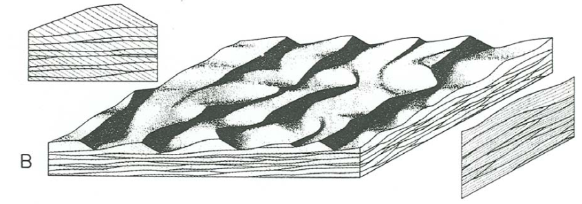
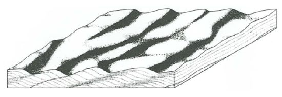
Figure \(\PageIndex{4}\) is a block diagram of cross stratification produced by three-dimensional dunes in unidirectional flows. It shows the dune-covered bed surface and sections perpendicular to the overall plane of stratification and parallel and transverse to the flow direction. Most of what I said about the analogous section in Figure \(\PageIndex{1}\) for cross stratification produced by ripples at low angles of climb is applicable to Figure \(\PageIndex{4}\) as well. Set thickness ranges from less than \(10\) \(\mathrm{cm}\) to as much as a few meters.
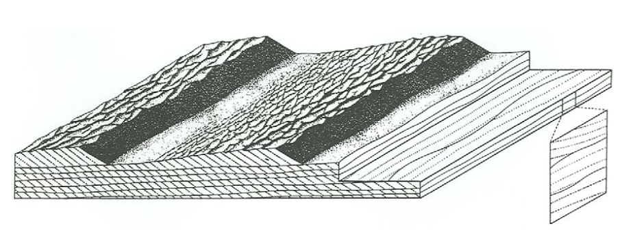
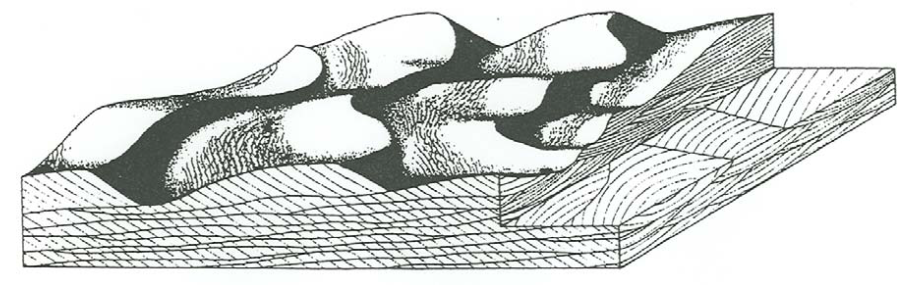
Figure \(\PageIndex{4}\) is a corresponding block diagram of cross stratification produced by almost perfectly two-dimensional dunes in unidirectional flows. The stratification geometry is rather different from that in Figure \(\PageIndex{3}\): in flow- parallel sections the sets extend somewhat farther and the set boundaries are less sinuous, but the greatest difference is in flow-transverse sections, where both the sets and the truncational set boundaries are much more extensive and show much less upward concavity. This is because of the absence of locally strong scour swales in the troughs of the dunes.
There is a whole spectrum of intermediate cases for which the cross- stratification geometry is less regular than the extreme case shown in Figure \(\PageIndex{5}\) but not as irregular as in Figure \(\PageIndex{4}\).
In both Figure \(\PageIndex{4}\) and Figure \(\PageIndex{5}\), the angle of climb of the dunes is very small. Dunes sometimes climb at higher angles, but that is not nearly as common as for ripples, because it is uncommon for fairly coarse sediment to be settling abundantly out of suspension over large areas to build up the bed rapidly. In the very few cases I have seen, the geometry of cross stratification is very much like that shown in Figure \(\PageIndex{3}\).
Telling Bed-Form Size from Erosional-Stoss Climbing-Bed-Form Cross Stratification
From depositional-stoss climbing-bed-form cross stratification, you can find both the height and the spacing of the bed forms by direct measurement. With the more common erosional-stoss climbing-bed-form cross stratification, however, it is much more difficult to get an idea of either the height or the spacing of the bed forms, because their profiles are not directly reflected in the geometry of the cross stratification.
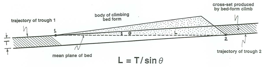
If you know, independently, the orientation of the overall plane of stratification—which you also cannot read from the geometry of the cross stratification itself, but which you might know from the upper and lower contacts of the cross-stratified bed—then in theory you can find the spacing by use of the simple equation
\[ L= \frac{T}{\sin \theta} \label{16.1} \]
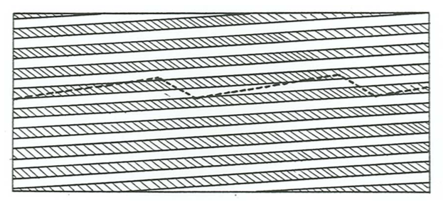
where \(L\) is the bed-form spacing, \(T\) is the thickness of cross sets, measured perpendicular to the set boundaries, and \(\theta\) is the angle of climb. (I invite you to try to derive this equation for yourself; it is not difficult to derive, by use of some trigonometry.) Figure \(\PageIndex{6}\) is a sketch that shows these variables, and the geometry of the climbing-ripple cross stratification. The trouble with Equation \ref{16.1} is that it is applicable only when the cross sets are fairly regular in their thickness.
That leads us to the problem of how to estimate the bed-form height from the preserved cross stratification. It should make good sense to you that, in a qualitative way, for a given bed-form size the smaller the angle of climb, the smaller the percentage of bed-form height represented by the set thickness. You can derive an equation similar to Equation \ref{16.1} for bed-form height as a function of set thickness and angle of climb, but it is more complicated, because the solution depends on the angle of the stoss slope and the angle of the lee slope as well as on \(T\) and \(\theta\):
\[H = \frac{T \tan \alpha \tan \beta}{\sin \theta (\tan \alpha + \tan \beta)} \label{16.2} \]
But for an angle-of-repose lee slope (about \(30^{\circ}\)) and a stoss slope of between ten and fifteen degrees, Equation \ref{16.2} specializes to
\[H \cong 0.15 \frac{T}{\sin \theta} \label{16.3} \]
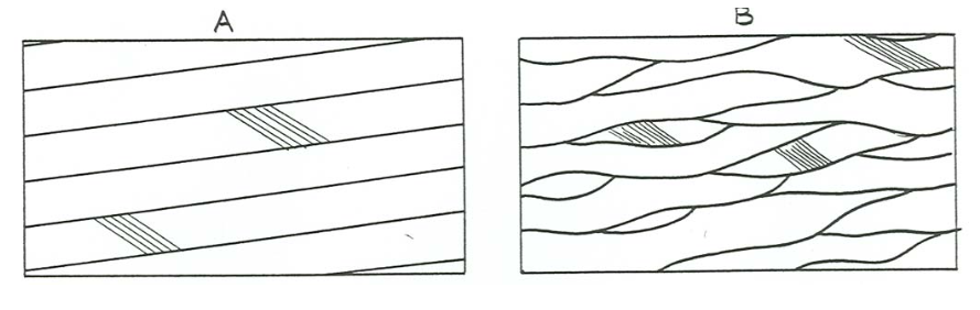
But all of the above applies only to regular bed forms climbing regularly. That is usually not the case, because, as you saw in Chapter 12, both large-scale and small-scale bed forms in unidirectional flow can be very irregular. In particular, the depth of scour in the troughs can vary greatly from place to place and from time to time, with the result that the sets vary greatly in thickness when viewed in flow-parallel section. Then the average set thickness is greater than given by Equations \ref{16.2} or \ref{16.3}. You can appreciate that qualitatively just by realizing that, even at zero angle of climb, bed forms with temporarily deep troughs must leave thick, but localized, sets of cross-laminae. Paola and Borgman (1991) have calculated that, for bed forms with essentially random variability of trough depth, the average set thickness is only slightly less than the average bed- form height and is not very sensitive to the angle of climb. If you were able to measure the “negative” thickness of lamina sets now gone forever by erosion, they would balance out the “positive” thickness of the preserved lamina sets—but we see only the “positive” thickness, not the “negative thickness.) For bed forms that have elements of both regularity and randomness, the truth would lie somewhere in between the two approaches noted above. That does not help much in concrete situations, but it is the best we can do at this stage in our understanding. Figure \(\PageIndex{7}\) shows the two end-member cases of extreme regularity and extreme randomness in erosional-stoss bed-form climb.
Cross Stratification Produced by Antidunes
Antidunes do produce cross-stratification, but the lamination tends to be obscure, so the preservation potential is low. A number of studies in laboratory flumes (Jopling and Richardson, 1966; Hand, 1969, 1974; Shaw and Kellerhals, 1977; Cheel, 1990; Alexander et al., 2001) and in ancient sedimentary deposits (Walker, 1967; Hand et al., 1969; Skipper, 1971; Schmincke et al., 1973; Prave and Duke, 1990; Yagishita, 1994; Massari, 1996) have revealed or interpreted the existence of such stratification.
Cross Stratification in Oscillatory Flow
Recall from Chapter 12 that in truly symmetrical oscillatory flow at low to moderate oscillation periods and low to moderate oscillation speeds the bed configuration is symmetrical two-dimensional oscillation ripples. Under these conditions, the sediment transport is also strictly symmetrical in the two flow directions. You might expect the ripples to remain in one place indefinitely. Then, if sediment is supplied from suspension to build up the bed, symmetrical oscillation-ripple cross stratification with vertical climb would be produced (Figure \(\PageIndex{8}\)). Although stratification of this kind is present in the sedimentary record, it is not common, presumably because even in purely oscillatory flow there is usually a minor degree of asymmetry of sediment transport, which causes the ripples to move slowly in one direction or the other.
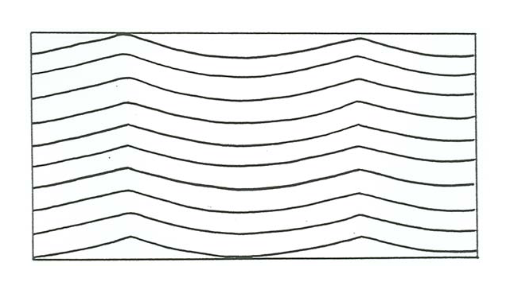
Figure \(\PageIndex{9}\) is an attempt to account for types of oscillatory-flow cross stratification produced by the buildup of two-dimensional oscillation ripples as a function of the slow net rate of ripple movement and the rate of aggradation of the bed. Along the vertical axis, for zero ripple movement, is symmetrical oscillation-ripple cross stratification, of the kind that I mentioned above might be expected on the basis of deduction. The chevron-like interleaving of laminae at the ripple crests, shown schematically, results from minor shifts in crest position back and forth during aggradation. This is shown by the first box from the top in Figure \(\PageIndex{9}\).
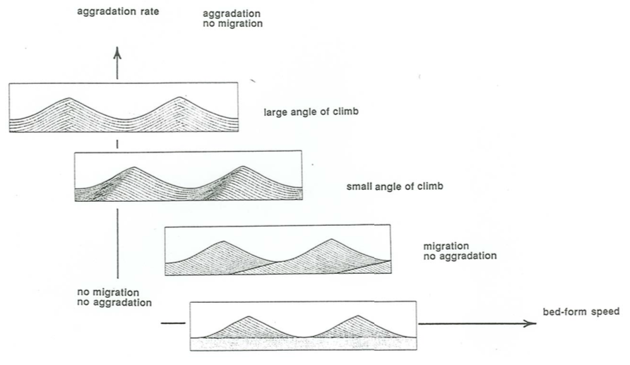
If the ripple speed is nonzero but slow relative to aggradation rate, the angle of climb is steep and the entire ripple profile is preserved (see the second box from the top in Figure \(\PageIndex{9}\)). If the ripple speed is large relative to the aggradation rate, ripple troughs erode into previously deposited laminae, and the stratification shows laminae dipping in one direction only, in sets bounded by erosion surfaces (see the third box from the top in Figure \(\PageIndex{9}\)). This last type is the most common in the sedimentary record. Finally, if a preexisting bed is molded into slowly shifting oscillation ripples without any net aggradation of the bed, the thickness of the cross-stratified deposit is equal to only one ripple height (see the bottom box in Figure \(\PageIndex{9}\)).
Stratification that is represented by the third sketch from the top in Figure \(\PageIndex{9}\), for a small angle of climb such that the individual lamina sets are separated by truncation surfaces, differs only in detail, rather than in general features, from low-angle climbing-ripple cross stratification produced by ripples in unidirectional flows, discussed in the previous section. In the field it can be a challenge to tell the two kinds apart. The regularity of the sets is generally greater in the oscillatory-flow case, but newly developing climbing current ripples can show just as great a degree of regularity.
In the real world, oscillation-ripple stratification is likely to be more complicated, because wave conditions seldom remain the same for long. Commonly there are a large number of sets of laminae dipping more or less randomly in both directions.
The origin and classification of stratification produced by oscillatory flows at longer oscillation periods and higher oscillation velocities is less well understood, because there have been very few studies in natural environments in which first the bed configuration was observed while the flow conditions were measured and then the bed was sampled to see the resulting deposit. Also, there have been few studies of these bed configurations under laboratory conditions. Another element of complexity is that in the natural environment the oscillatory flows are likely to be more complicated than the regular and symmetrical bidirectional oscillatory flows that were assumed above, and not much is known in detail about the stratification types produced by these more complicated oscillatory flows.
In the face of this seemingly hopeless situation, I will take the following approach. I will describe in a general way a common style of medium-scale to large-scale cross stratification, called hummocky cross stratification, which is generally believed to be produced by an oscillatory flow of some kind, and I will present what evidence I can for the kinds of flows that might produce hummocky cross stratification.
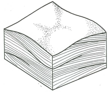
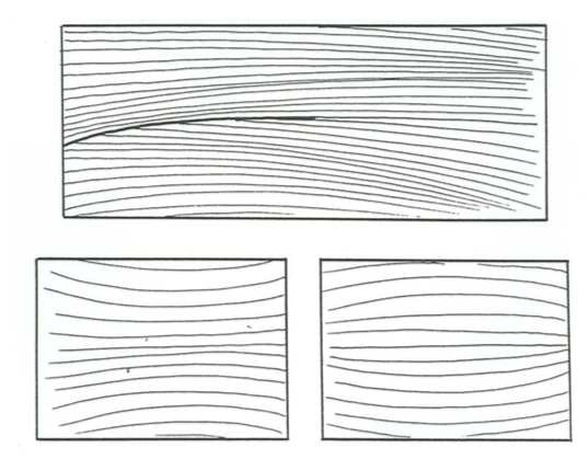
Figure \(\PageIndex{10}\) is a block diagram of one of the common styles of cross stratification that been called hummocky cross stratification. It shows sets of laminae that are both concave upward and convex upward, bounded by broad truncation surfaces which themselves may be either concave or convex upward. Two characteristic small-scale features of the geometry of stratification are the fanning of truncation surfaces laterally into conformable sequences of laminae (Figure \(\PageIndex{11}\)A) and, where the thickness of the bed is great enough to observe this, a tendency for convex-up sets of laminae to be succeeded upward by concave-up sets, and vice-versa (Figure \(\PageIndex{11}\)B).
Note that the two normal-to-bedding faces of the block are shown to have about the same style of stratification, and on each face there is no strongly preferred dip direction. In the rare cases where you can make serial sections of the deposit to ascertain the entire three-dimensional geometry of the deposit, it is clear that there is no preferred dip direction in the entire deposit. This is the kind of stratification I call isotropic.
The upper surface of the block diagram in Figure \(\PageIndex{10}\) is shown to be a bedding surface with a bed configuration that could be described as a collection of hummocks (locally positive convex-up areas) and swales (locally negative concave-up areas). Sometimes, but not often, the upper surface of a bed with hummocky cross stratification can be seen to have just this bed geometry. The general belief is that isotropic hummocky cross stratification is produced by this kind of bed configuration, although it is seldom possible to actually demonstrate this.
Recent experiments (Dumas et al., 2005) have shown that bed configurations which in their general features are like those just described are produced by symmetrical bidirectional oscillatory flows at long periods and high oscillation velocities. This suggests that at least some isotropic hummocky cross stratification is produced by such flows. But it also seems likely that more complex oscillations with more than one oscillatory component would also produce qualitatively similar bed configurations and therefore similar cross- stratification. Much more work needs to be done before the origin of hummocky cross stratification is well understood.
The style of stratification that people call hummocky cross stratification covers a wide range in scale and geometry. It seems likely that hummocky cross stratification, used in the broad sense as a descriptive rather term than as a genetic term, is polygenetic: several distinctly different kinds of flow and sedimentation settings produce stratification that at least some workers would want to call hummocky cross stratification. There have even been published reports in recent times (Alexander et al., 2001) of a kind of stratification, which might be described, objectively, as a kind of hummocky cross stratification, that develops by aggradation of the bed while antidunes were present and changing their shape and position in some way.
Classification of hummocky cross stratification, in the wide sense of the term, is not in a very advanced state, and yet a rational classification would be useful, in view of the commonness and the multiplicity of origin of hummocky cross stratification. Figure \(\PageIndex{12}\) is my own unofficial attempt at such a classification. In my own examination of hummocky cross stratification I have found this classification to be a useful guide to my thinking about the origin of the stratification. The elements in the classification are as follows.
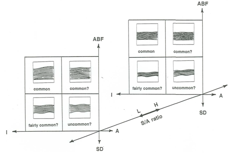
The eight varieties represented on the graph could be named as follows:
upper left, front: isotropic aggrading-bed-forms slow-shift HCS
upper right, front: anisotropic aggrading-bed-forms slow-shift HCS
lower left, front: isotropic scour-and-drape slow-shift HCS
lower right, front: anisotropic scour-and-drape slow-shift HCS
upper left, rear: isotropic aggrading-bed-forms fast-shift HCS
upper right, rear: anisotropic aggrading-bed-forms fast-shift HCS
lower left, rear: isotropic scour-and-drape fast-shift HCS
lower right, rear: anisotropic scour-and-drape fast-shift HCS
Isotropy vs. anisotropy: This has to do with the extent to which the cross sets have a preferred dip direction and/or dip angle. This must be controlled by the asymmetry of the oscillatory flow and/or the superimposition of a unidirectional flow component. As the stratification becomes more anisotropic, it might better be viewed as combined-flow stratification rather than as purely oscillatory-flow stratification.
Ratio of aggradation to bed-form shift: Depending mainly on the relative importance of bed-form shifting vs. rate of aggradation, sets may be very restricted in lateral extent and show mainly concave-up laminae (most workers would probably call this swaly cross stratification), or they may be continuous over a greater lateral distance and show more convex-up laminae.
Draping vs. bed-form maintenance: hummocky cross stratification can be formed by scouring of a hummocky–swaly bed topography initially and then draping of that irregular bed surface without the participation of oscillatory-flow bed forms that are in equilibrium, or not far out of equilibrium, with the flow. Alternatively, it can be formed by bed forms that are maintained by the flow during overall aggradation of the bed.
Scale: the scale of hummocky cross stratification ranges from quite small (what many would simply call three-dimensional wave-ripple cross stratification) to large (sets a few decimeters thick and with lateral extent of a meter or two). The scale must have a fairly direct link to the original size of the geometrical elements that existed on the sediment bed during deposition, although the vertical scale must depend also on the rate of net aggradation of the bed.
Extent of amalgamation: It is common to find single hummocky cross- stratified beds, but it is equally common to find sandstone beds that consist of two, three, or even more amalgamated beds, separated by through-going amalgamation surfaces, with each amalgamation unit showing hummocky cross stratification of one kind or other (or planar lamination, especially the lowest amalgamation unit in the succession).
Of course, it is not possible to represent a five-dimensional classification graphically! What Figure \(\PageIndex{12}\) shows is a three-dimensional pigeonhole arrangement with the first three attributes in the above list, leaving scale and extent of amalgamation as additional descriptors.
Here are a few tentative comments about the classification shown in Figure \(\PageIndex{12}\).
- The four cartoons of scour-and drape hummocky cross stratification are end-member cases. What I think is much more common is stratification that is largely scour and drape but with bed topography changing at least slightly as the drape forms, so that the internal structure of the bed is not quite as regular and conformable as shown in the cartoons.
- When the stratification is largely of the scour-and-drape variety, I see no way to tell whether the S/A ratio was low or high; with aggrading-bed forms HCS, on the other hand, that is easier to do, at least in a qualitative way, by looking at the abundance and lateral extent of truncation surfaces.
- The case in the upper right rear (“anisotropic aggrading-bed-forms fast- shift hummocky cross stratification”) might also be described as a kind of combined-flow trough cross-stratification, and as the importance of the unidirectional flow component increases and that of the oscillatory flow component decreases, this kind of stratification grades over into the trough cross stratification that is familiar to all.
Combined-Flow Cross Stratification
This brings us to the problem of combined-flow cross stratification. Unfortunately there is an almost complete lack of observational information on the origin of combined-flow cross stratification, so we have no actual models to guide interpretations. Up to now the recognition of combined-flow cross stratification has largely been a matter of deduction.
It seems convenient to think separately about the relatively small combined-flow ripples produced under combinations of relatively low oscillatory and unidirectional flow velocities, on the one hand, and the relatively large combined-flow ripples produced under combinations of relatively high oscillatory and unidirectional flow velocities, on the other hand.
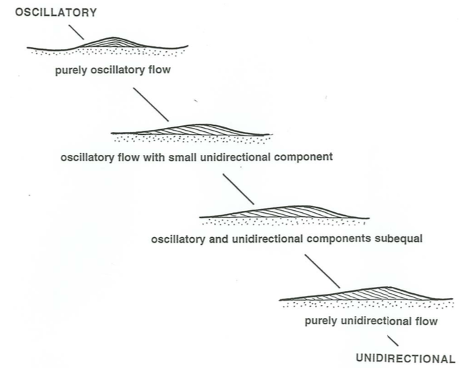
When the combinations of oscillation period and oscillation velocity are such that in purely oscillatory flow the ripples would be at about the same scale as current ripples, there is a kind of coherence in the combined-flow ripples: they are on the same scale as unidirectional-flow ripples, but more nearly two- dimensional. Actual experiments indicate that only a very small unidirectional component is needed to make such ripples noticeably asymmetrical.
Figure \(\PageIndex{13}\) shows a series of flow-parallel profiles of ripples formed under a range of combined flows, from purely oscillatory to purely unidirectional One striking thing about such ripples is that it takes only a very slight unidirectional component for the ripples to shift slowly in their position, even though the profile is still virtually symmetrical. The top sketch in Figure \(\PageIndex{13}\), which is drawn as if the ripple stayed in the same place as it developed from the sandy substrate, is therefore a bit unrealistic, because even symmetrical ripples usually show one-way internal lamination. With even a fairly small unidirectional component the ripples become noticeably asymmetrical, as in the second sketch from the top in Figure \(\PageIndex{13}\). By the time the oscillatory and unidirectional components are both substantial, as in the third sketch from the top, the ripples do not look much different from those produced in purely unidirectional flows, except that the profile is typically a little more rounded and the slope of the lee side is somewhat less.
For very short periods or very long periods, however, when the ripples that would be produced in purely oscillatory flow are much smaller or much larger than current ripples, the situation is more complicated, because in combined flows the bed configuration wants to be at two separate scales, and there is a complicated interaction between the two differing scales. There has not been much study of the stratification produced under these combined-flow conditions.
When the oscillation period is so small that the oscillation ripples are much smaller than current ripples, their dominantly oscillatory nature is clear. But there is still a problem, because the spacing of current ripples when they first become organized on a preexisting planar sand surface is no more than six or seven centimeters, and then they grow to their full size of something like fifteen to twenty centimeters. Only for ripples smaller than six or seven centimeters, therefore, can you be sure that you are dealing with dominantly oscillatory ripples and not unidirectional-flow-dominated ripples that are still growing toward equilibrium.
Eolian Cross Stratification
So far the discussion has implicitly been directed toward subaqueous bed configurations. Everyone knows that the shifting of eolian dunes produces large-scale cross stratification as well.
I can make a first-order statement here without fear of contradiction: eolian dune cross stratification is similar in gross aspects to large-scale trough cross stratification produced by water flows. Behind the gross similarity, however, are real differences. These differences are simply a consequence of the differing details of geometry of the dunes themselves.
Although I have looked at a fair number of cross-stratified eolian units, I find it difficult to be specific or concrete about how eolian dune cross stratification differs from subaqueous dune cross stratification. Here are some points of difference. (I do not pretend this to be an exhaustive list.)
- In eolian cross stratification there is a tendency for the laminae in the cross sets in the downwind part of the set to dip in the direction opposite to the dune movement. That tends to be in contrast to cross stratification produced by subaqueous dunes, for which an upcurrent dip direction of the laminae in the cross sets is much less pronounced. I think that that feature reflects the tendency for the troughs of eolian dunes to be filled by plastering of new trough laminae not just on the mean-upcurrent side, as is usually the case in subaqueous cross stratification, but on the lateral and mean-downcurrent sides as well.
- Eolian cross stratification is more likely to show greater dispersion of dip directions of cross sets, because of the greater variability of wind directions than of subaqueous current directions. (But this is not as strong a tendency as you might think, because most of the major eolian sand bodies preserved in the sedimentary record were probably produced in sand seas swept by winds fairly constant in direction.)
- The nature of the lamination in eolian cross-sets tends to be different from that in subaqueous cross-sets. The three basic kinds of laminae in cross-sets (see Hunter, 1977a) are:
- grain-flow laminae, produced by the downslope movement of grain flows to iron out the oversteepening of the foreset slope caused by deposition at the brink.
- grain-fall laminae, produced by the rain of sand grains onto the foreset slope after they are carried across the brink in saltation.
- translatent laminae, produced by the movement and very-low-angle climb of ripples on sand surfaces that are undergoing net aggradation.
The first two kinds of laminae are common to both subaerial and subaqueous cross sets, but they are much more distinctive and better differentiated in subaerial deposits. Translatent laminae are specific to subaerial deposits, because in subaqueous environments the scale and movement of ripples in dune-lee environments is such as to produce recognizable small-scale cross lamination rather than laminae so thin that the cross-stratified nature is undetectable, as in the eolian case.
Here is another, and rather different, consideration that can be useful in some cases in distinguishing subaerial from subaqueous cross stratification.
Think back to the velocity–size diagram for subaqueous unidirectional-flow bed phases. The minimum mean particle size for the existence of dunes is shown to be about \(0.16\) \(\mathrm{mm}\). When the effects of water temperature and therefore water viscosity are taken into account, that translates (by a computational procedure that I will not describe here; see Southard and Boguchwal, 1990) into a range of minimum sizes from \(0.20\) \(\mathrm{mm}\) at \(0^{\circ} \text{C}\) to \(0.12\) \(\mathrm{mm}\) at \(30^{\circ} \text{C}\). If the mean size of the sediment in the cross sets in question is significantly finer than these sizes, then the deposits are almost certainly eolian rather than subaqueous. (How you estimate what the water temperature might have been is, of course, another matter.) There is an important qualification to this conclusion, however: you must be able to rule out the possibility that, if the cross stratification is subaqueous, it was indeed the result of the movement of dunes, and not of fluvial bars, whose sediment size might be finer than the lower limit associated with dunes. The overall geometry of the cross stratification usually makes that decision possible.