
12.4: Movement of Ripples and Dunes
- Page ID
- 4228

Sediment Movement over Ripples and Dunes
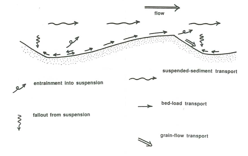
The mode of sediment transport varies greatly from place to place over the ripple or dune profile. A repetition of your traverse, this time to watch the sediment movement, would be instructive. See Figure \(\PageIndex{1}\) for a key to the material discussed below. Start at the reattachment zone, where the time-average bed-load transport rate is near zero. Strong eddies in the reattaching shear layer impinge upon the bed to cause strong but sporadic grain transport. At low mean- flow velocities, sediment is shifted this way and that on the bed in local pulses that strike seemingly at random. This is the site of first suspension of sediment as flow velocity gradually increases: swirls of sediment are put into suspension in puffs and gusts, and then the grains either settle directly back to the bed or are dispersed up into the flow.
Downchannel from reattachment the pulses of movement are directed more and more consistently downchannel and gradually give way to more uniform grain movement up the stoss slope. In the other direction they cease to be important just a short distance upchannel from reattachment, because flow in the separation vortex behind the bed form is relatively weak.
Particle movement up the stoss surface is much like that on a planar sediment bed: it is in the form of isolated puffs at low mean-flow velocities, and in the form of a continuous sheet at higher velocities. With increasing velocity the bed-load movement is obscured by sediment suspended from the trough or from upstream ripples. Dunes often have ripples or even smaller dunes superimposed on their stoss slopes; this should not surprise you, because such bed forms develop wherever they have sufficient space and suitable flow conditions.
At low flow velocities all of the sediment that is transported as bed load to the brink is deposited there. This sediment tends to build the stoss surface forward over the top of the lee surface. The sediment slips down the lee surface as a kind of grain flow to try to restore a stable angle of repose. Grain flow is localized and sporadic when the rate of delivery is slow but widespread and continuous at higher flow velocities. The result is a nearly planar slip face, with a break in slope not only at the top but also at the base, where the slip face builds forward onto the surface of the trough downstream.
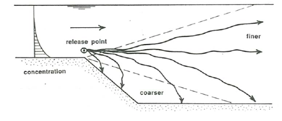
At higher flow velocities some fraction of the transported grains are carried beyond the crest above the separation surface, to settle through the complicated turbulent flow field in the wake of the ripple and land at various points (Figure \(\PageIndex{2}\)): on the slip face, in the trough, on the stoss surface of the next ripple downstream, or even on some ripple much farther downstream. Where the grains land depends on several factors: the flow velocity, the settling velocity, the height of the grains above the bed as they pass over the brink, and which eddies the grains happen to fall through.
When the ripple geometry is three-dimensional, many troughs show no well defined separation vortex, and patterns of flow and sediment transport are not as simple as outlined above. The bed surface near the base of the lee slope nonetheless usually feels flows that are much weaker than over the stoss slope, although these flows may have a substantial cross-stream component. Transverse flow in the lee of the dunes often makes ripples in troughs and on lee slopes, with crests oriented at a large and variable angle to the dune crests.
Movement of Ripples and Dunes
Ripples and dunes move downstream, at speeds that are orders of magnitude slower than the flow speed, by erosion on the stoss surface and deposition on the lee surface. It is surprisingly difficult to characterize this downstream movement, partly because the bed forms change their profiles with time but even more importantly because any given bed form has a finite lifetime: it is born, it moves, and it eventually dies, usually within a travel distance equal to only a small multiple of the bed-form spacing, something like \(5–10\) spacings. The moderately regular arrangement of ripples in a still photograph is deceiving. This section says some things about the nature and analysis of movement of ripples and dunes.
A fundamental characteristic of ripples is that they move downstream at some velocity \(U_{B}\), by erosion on the stoss surface and deposition on the lee surface. This velocity is of interest because
- it is an index of bed-load transport rate, because we have seen that most of the bed load moving on a ripple bed is cycled within the same ripple, and
- it is one of the determinants of the stratification geometry produced by ripple movement.
This section addresses the measurement of \(U_{B}\), along with some results, and also its use in estimating sediment transport rates. A discussion of its role in the geometry of sedimentary structures would take us too far afield; see papers by Allen (1970), Ashley et al. (1982), Rubin and Hunter (1982), and Harms et al. (1982, Chapter 3).
It is surprisingly difficult to characterize the downstream movement of ripples. If each ripple had an unchanging streamwise profile, \(U_{B}\) would be both well defined and readily measurable. Because most ripples have a fairly sharp break in slope at the brink, it is usually no problem to follow a distinguishable point on the profile as the ripple moves. But the profile shape changes as the pattern of sediment transport over the ripple changes, even if the profile area stays the same. This usually causes the position of the brink to change relative to the center of area of the ripple over just a short distance of movement, so even the position of a well defined point on the profile does not necessarily represent well the position of the ripple. Moreover, the profile area of a ripple itself is changed by several processes, which can act concurrently:
- intensification of scour in a trough and deposition of the eroded sediment on the stoss surface or farther downstream;
- transfer of sediment from one ripple to another by either bed-load transport or suspended-load transport;
- overriding of one ripple by the next ripple upstream;
- division of one ripple into two, as a new trough develops on the stoss surface of a ripple as a result of some change in upstream flow pattern.
The last two processes imply that ripples do not live forever: they come into being, move for some distance that is usually a small number of ripple spacings, and then disappear.
A good way to apprehend the transitory existence of individual ripples is to generate a train of ripples in your flume and photograph them with a time- lapse movie camera as they move downstream. When you viewed the film at normal speed you would see the ripples doing all sorts of crazy things that are hard to appreciate by real-time viewing; the moderately regular succession of ripples when viewed in a still picture is deceiving. Two other instructive things you could do are described in the following paragraphs.
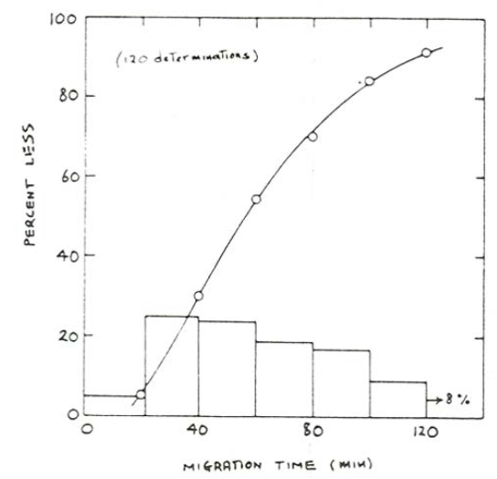
You might stock up on sandwiches and caffeine, occupy a station somewhere along the channel, and for a large number of ripples measure the time \(T_{r}\) needed for two successive ripple crests to pass the station. After getting some rest you could then plot a cumulative distribution of \(T_{r}\). (When multiplied by the spacing of the passing ripple, the inverse of \(T_{r}\) is a good representation of \(U_{B}\).) Figure \(\PageIndex{3}\), measured by Southard et al. (1980), is such a curve. Note the wide range in passage times. It was found that hundreds of ripples would have had to be measured to obtain a stable cumulative curve, although substantially fewer were sufficient for a stable mean value.
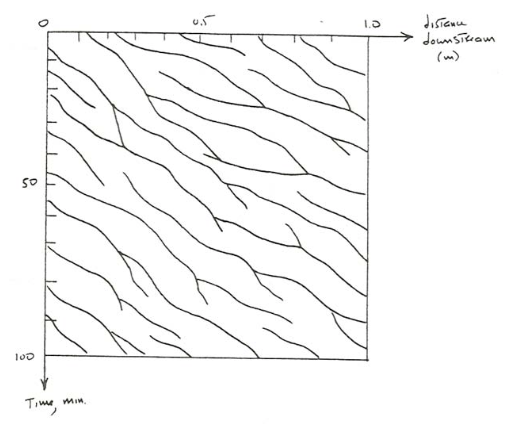
To quantify the variability in ripple movement you might enlist a large number of volunteers to stand along the transparent sidewall and be responsible for keeping track of the positions of the ripples as a function of time. A plot of position vs. time would look like Figure \(\PageIndex{4}\), from which you can see that
- for a given ripple \(U_{B}\) varies widely and irregularly with time;
- a given ripple exists for a distance of movement that is only a few ripple spacings;
- ripples usually are born by division of one large ripple into two smaller ones, and usually die by becoming smaller and slower and then being overridden by a faster-moving ripple (on the average, deaths equal births).
Despite all of this variability, when considered as an aggregate the lines in the graph have a definite average slope, which is probably the best measure of \(U_{B}\).
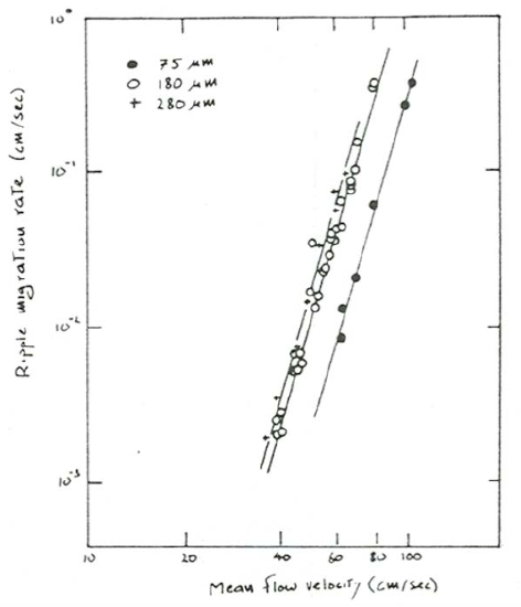
You should expect \(U_{B}\) to increase steeply with mean flow velocity \(U\) for a given sand, because, as you will learn in Chapter 12, bed-load transport rate increases steeply with flow strength and most of the bed load remains within individual ripples. The magnitude of this increase depends, however, on the concurrent change in ripple size, because the larger the ripple, the slower it moves for a given bed-load transport rate. The effect should therefore be most pronounced for ripples, which vary little in size with flow conditions and sediment size. Systematic data on bed-form velocity as a function of flow strength and sediment size are surprisingly scarce, presumably owing to the difficulty of accurate measurement. Figure \(\PageIndex{3}\), a plot of \(U_{B}\) vs. \(U\) for three different sand sizes (Dillo, 1960), shows that \(U_{B}\) increases sharply with \(U\) for a given sand size, as expected. Note, however, that ripples in coarser sands move faster than ripples in finer sands. The reason for this seemingly anomalous behavior is unclear. There seem to be two possibilities:
- The volume transport of sand as traction load in the accelerating flow over the stoss face of the ripple might be greater in coarser sand than in finer sand at a given mean flow velocity.
- The ripples in the coarser sand may have been smaller than in the finer sand, so that \(U_{B}\) is greater even though bed-load transport rate might have been smaller.
In the absence of suspension, particles are cycled through individual bed forms. Think about a particle in the interior of a moving bed form (a ripple or a dune). The particle is of course stationary relative to the substrate. As the bed forms moves, the particle finds itself closer and closer to the stoss surface. When it become exposed at the surface, it is entrained, moves up to the brink as part of the bed load, and then slumps or slides down the lee slope, stopping at some point on the slope (or at its base), there to be buried by later lee-side deposition to become entombed again, temporarily, within the body of the bed form.
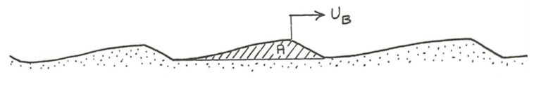
To the extent that the moving sediment is cycled within bed forms, the bed-load transport rate can be expressed in terms of the speed of movement of the bed forms. For ripples this is a good approximation, because bed-load transport rate is usually zero or nearly so at some point in the trough. Only if bed-load transport rate is nowhere zero over the bed-form profile, as is generally the case with antidunes, is this not true. To derive an expression for the bed-load transport rate associated with bed-form movements, consider a train of identical bed forms in which bed-load transport rate is zero in the troughs (Figure \(\PageIndex{4}\)). The ripples have cross-sectional area \(A\) and spacing (i.e., repeat distance of cross-section geometry) \(L\). The time needed for passage of a bed form past a given point is \(T_{r}\). The rate \(q_{f}\), expressed per unit width normal to the flow, at which volume of sediment is moved downstream by bed-load transport within the ripples (remember that this involves stripping of sediment from the stoss surface, dumping at the crest, and slumping down the lee surface) is the same as the rate of downstream shift of the ripple cross section, except for a correction factor discussed below. A good way of thinking about this is to consider that the entire cross-sectional area of the ripple passes a given point on the bed in time \(T_{r}=L / U_{B}\), so the average rate of passage of cross-sectional area past the point during this time is \(A / T_{r}\), or, eliminating \(T_{r}\), \(A U_{B} / L\). So
\[q_{f}=K_{1} \frac{A U_{B}}{L} \label{12.25} \]
For a more elegant derivation of this result, see Simons et al. (1965).
The correction factor \(K_{1}\) is needed because the transport rate is expressed as solids volume whereas bed volume is expressed as bulk volume, solids plus void space. It is easy to derive a relationship between solids volume \(V_{s}\) and bulk volume \(V_{b}\) in a sediment sample. Because voids volume and solids volume add up to total volume in a sediment,
\[V_{v}+V_{s}=V_{b} \label{12.26} \]
where \(V_{v}\) is voids volume. Also, the porosity \(k\) is defined as
\[\lambda=\frac{V_{v}}{V_{b}} \label{12.27} \]
Combining Equations \ref{12.26} and \ref{12.27} to eliminate \(V_{v}\) gives the relationship between solids volume and bulk volume:
\[V_{b}=\frac{1}{1-\lambda} V_{s} \label{12.28} \]
Because \(\lambda\) in equant and fairly well sorted sediments is on the order of \(0.2–0.4\), depending on both sorting and packing, the porosity correction factor \(1/(1-\lambda)\) is always positive and a little larger than one. Using Equation \ref{12.28}, Equation \ref{12.25} becomes
\[q_{f}=\frac{1}{1-\lambda} \frac{A U_{B}}{L} \label{12.29} \]
In the rest of this chapter \(1/(1-\lambda)\) will be written \(K_{1}\) for convenience. If the bed forms have the shape of end-to-end triangles with height \(H\), then \(A = H L/2\) and Equation \ref{12.29} becomes
\[q_{f}=K_{I} \frac{H U_{B}}{2} \label{12.30} \]
Rubin and Hunter (1982) proposed that \(q_{f}\) be called the bed-form transport rate and that the remainder of the bed-load transport rate, the part that bypasses the bed forms rather than being cycled within the same bed form, be called the throughgoing transport rate.
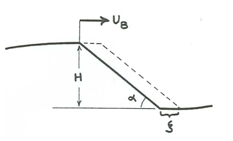
The bed-load transport rate (call it \(q_{sb}\)) is greatest at the crests of ripples. An expression for \(q_{sb}\) at a ripple crest can be derived on the assumption that all the bed load arriving at the crest is dumped there to slump down the lee face and build it forward (Figure \(\PageIndex{5}\)). The slip-face angle is \(\alpha\) and the horizontal distance of slip-face outbuilding is \(\zeta\). As before, ripple velocity is \(U_{B}\) and ripple height is \(H\). The principle is that \(q_{sb}\) at the crest is equal to the time rate of addition of bulk sediment volume on the slip face. Because the increment in volume of the slip-face deposit is just the thickness of the slip-face deposit, \(\zeta \sin \alpha\), times the length down the slip face, \(H/\sin \alpha\),
\(\begin{aligned} q_{s b} &=K_{1} \frac{d}{d t}\left[\left(\zeta \sin \alpha \frac{H}{\sin \alpha}\right)\right]\\\\ &=K_{1} \frac{d(\zeta H)}{d t} \\\\ &=K_{1} H \frac{d \zeta}{d t} \end{aligned}\)
\[=K_{1} H U_{B} \label{12.31} \]
By comparison of Equations \ref{12.30} and \ref{12.31} we have the neat result that, for ripples with triangular cross-section, bed-load transport at the crests is exactly twice the average value. This result seems first to have been derived by Bagnold (1941).