
5.2.4: Diffraction
- Page ID
- 16321

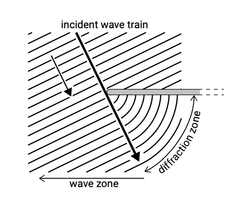
If obstructions to the wave propagation (an offshore island, a breakwater, a headland) or abrupt changes in the bottom contours are present, there is a large (initial) variation of wave energy along a wave crest which leads to transfer of energy along the wave crests. This phenomenon is called diffraction. Figure 5.7 shows the diffraction of an incident wave train in the case that there are no depth changes. A part of the wave front is blocked by the breakwater and is reflected seaward. The remainder of the wave front will bend around the obstacle and thus penetrate into the zone in the lee of the obstacle (shadow zone). The diffracted wave crests will form concentric circular arcs with the wave height decreasing along the crest of each wave.
Figure 5.7 also shows the wave ray that separates the shadow or diffraction zone from the wave zone. Due to the lateral transfer of wave energy into the shadow zone, the wave height along this ray is lower than the incident wave height; in the case of constant depth (and thus constant celerity), the wave height is 50% of the original wave height according to linear theory and order 70% for irregular directional waves. The wave heights decrease deeper into the shadow zone. Further from the breakwater into the wave zone the wave height gradually approaches the incident wave height.
The extent of energy penetration in the area landward of an obstacle depends on the ratio of a characteristic lateral dimension of the obstacle, e.g., the length of a single detached breakwater \(\lambda\) to the wavelength \(L\). When a thin pile is standing in waves with a large wavelength, \(\lambda /L \ll 1\), wave energy spreads behind the entire pile. In the case of a long detached breakwater, \(\lambda /L \gg 1\), diffraction occurs around each breakwater head, but wave energy will not spread in the entire zone behind the breakwater.
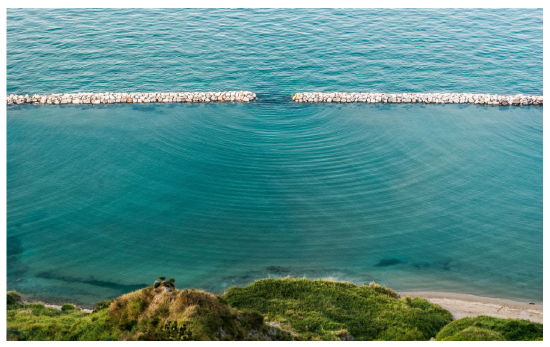
Figure 5.8 shows waves passing through a gap between two detached breakwaters. Diffraction occurs in the lee of the breakwaters on both sides of the gap. For large enough gap lengths (relative to the wavelength) these diffraction patterns are independent. Interaction of the two patterns may occur for smaller gap lengths.
The theory of wave diffraction is solved mathematically by application of the ‘Cornuspiral’ (see for instance Battjes (2006)). This graphical method yields spatially varying diffraction coefficients, defined as the ratio of the diffracted wave height to the incident wave height assuming that the latter is not disturbed by the obstacle. The CEM Chapter II-7 and (in more detail) the Shore Protection Manual Volume I Chapter 2 present diffraction coefficients as a function of position (relative to a semi-infinite rigid impermeable breakwater) and as a function of the breakwater gap width.
The disadvantage of the above methods is that they assume a constant water depth. In reality there will generally be a sloping bottom or an uneven bed and the results will therefore be influenced by this bottom. Numerical models can take into account shoaling, diffraction, refraction, reflection (and breaking) simultaneously.