
5.2.3: Refraction
- Page ID
- 16320

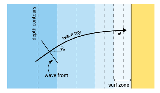
Instead of a normally incident wave, consider now an obliquely incident linear wave approaching at a deep water angle \(\varphi_0\) to the shore. The wave is again long-crested and the bottom contours are essentially straight and parallel as shown in Fig. 5.4. The wave is in the shoaling region outside the breaker zone.
When a wave approaches underwater contours at an angle, it is evident that the sections of the crest in the deeper parts travel faster than those in the shallower sectors. This causes the wave crest to turn towards the depth contour. This bending effect is called refraction, and is analogous to similar phenomena in physics (light, sound). The effect is shown in Fig. 5.5. It takes place in addition to the effects of shoaling and continues up to the shoreline.
In analogy with refraction of light, the direction of the wave rays changes proportionally to the wave propagation speed according to Snell’s law3:
\[\dfrac{\sin \varphi_2}{c_2} = \dfrac{\sin \varphi_1}{c_1}\label{eq5.2.3.1}\]
Thus along the wave ray \(\sin \varphi /c\) is constant and equal to its deep water value \(\sin \varphi_0 /c_0\). Eq. \(\ref{eq5.2.3.1}\) holds for breaking as well as non-breaking waves, but for straight, parallel depth contours only.
By applying Snell’s law, it is possible to construct a field of wave rays over a given bottom configuration for a given wave direction and wave period. The wave angle can thus be considered known in the energy balance, Eq. 5.2.1.2.
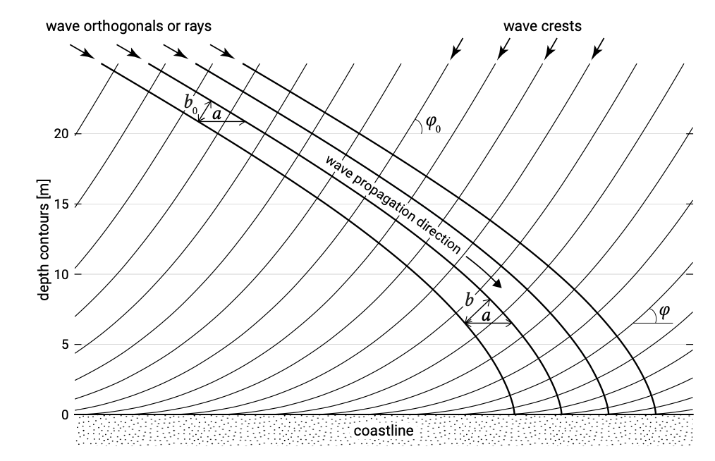
Figure 5.5 shows that the distance \(b\) between the wave rays varies. If we assume that for long-crested waves no wave energy moves laterally along the wave crest and thus that the energy remains constant between wave rays (normal to the wave crest), energy conservation between two wave rays requires that (cf. Eq. 5.2.1.3):
\[Encb = \text{const} \to H_2^2 n_2 c_2 b_2 = H_1^2 n_1 c_1 b_1\]
The wave height at two locations therefore relates as:
\[\dfrac{H_2}{H_1} = \sqrt{\dfrac{c_1}{c_2} \dfrac{n_1}{n_2}} \sqrt{\dfrac{b_1}{b_2}}\label{eq5.2.3.3}\]
Using \(n_0 = 1/2\) (deep water) the wave height \(H\) at any location can be related to the wave height in deep water:
\[\dfrac{H}{H_0} = \sqrt{\dfrac{1}{2n} \dfrac{c_0}{c} \dfrac{b_0}{b}} = K_{sh} K_r\]
where \(K_{sh}\) is the shoaling coefficient according to Eq. 5.2.2.4 and
\[K_r = \sqrt{b_0}{b}\]
is the refraction coefficient used to calculate the change in wave height when a wave approaches at an angle to the shore. Since for parallel depth contours every wave ray refracts the same way, the distance between given wave rays, measured parallel to the depth contours, remains constant (distance \(a\) in Fig. 5.5) and is equal to:
\[a = \dfrac{b}{\cos \varphi} = \text{const}\]
and thus
\[K_r = \sqrt{\dfrac{\cos \varphi_0}{\cos \varphi}}\]
This result for the wave height variation in the case of parallel depth contours could also be found directly from Eq. 5.2.1.2. Assuming an alongshore uniform situation (\(y\)-derivative equal to zero) outside the surf zone (dissipation negligible), integration yields:
\[Enc \cos \varphi = \text{const}\]
which directly results in Eq. \(\ref{eq5.2.3.3}\).
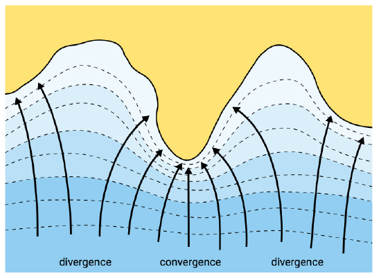
The effect of refraction on the wave height in the present example is to reduce the increase in wave height due to shoaling. In a real life situation with a more complicated pattern of depth contours, two basic calculating techniques are available for refraction patterns: graphically and numerically (see above). A description of the first method is given in the CEM. Fundamentally all methods of refraction analyses are based on Snell’s law and conservation of wave energy. A refraction diagram is given in Fig. 5.6 as an example of the results of a refraction study. If the wave rays converge there is an accumulation of energy and relatively high wave heights can be expected. In contrast if wave rays diverge the energy is spread over a larger part of the wave crest so the wave height is reduced.
Depth-refraction in obliquely incident shoaling waves was explained from differences in water depth and hence wave celerity along a wave crest. Refraction may also occur due to mean currents, in which case it is called current-refraction. When short waves interact with a current, amongst others the celerity of the waves is affected. Current-refraction takes place if the current velocity varies along a wave crest, e.g. in tidal entrances (Sect. 9.4.1), in major ocean currents, or in harbour entrance channels.
3. Named after the Dutch astronomer Willebrord Snellius (born Willebrord Snel van Royen) (1580-1626).