
10.2.1: Symmetry on Stereo Diagrams
- Page ID
- 18473

A convenient way to look at the symmetry of a crystal is to use a stereographic projection, also called a stereo diagram. Stereo diagrams allow us to depict three-dimensional symmetry in a two-dimensional diagram. Although stereo diagrams depict mirror planes, inversion centers, and rotational symmetry, and their relationships to crystal faces, stereo diagrams do not show the shape of faces. The diagrams only show symmetry.
10.2.1.1 Rotation Axes
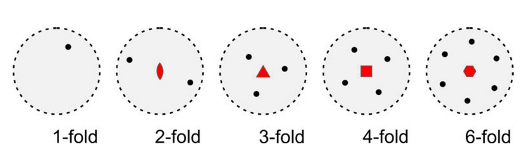
Stereo diagrams can be quantitative and very complex. In this text, considering their qualitative aspects is sufficient. Figure 10.18 shows stereo diagrams depicting 1-fold, 2-fold, 3-fold, 4-fold, and 6-fold rotation axes perpendicular to the page. The geometric symbols (in red) at the center of the diagrams show the kind of rotation axes. In the five drawings, the rotation axis has operated on a single black dot, producing 0, 1, 2, 3, or 5 other dots by rotation of 360°, 180°, 120°, 90°, and 60° around the center of the diagram.
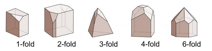
Figure 10.19 shows examples of crystals that have rotation axes. In drawings of this sort, it is often necessary to depict crystals with several differently shaped faces to limit symmetry and make the symmetry clear (as is done in this figure). It is easy to make drawings that have more symmetry than wanted. For example, if the top pyramid faces were not present, the crystals with 2-, 3-, 4-, and 6-fold symmetry would also contain vertical mirrors.
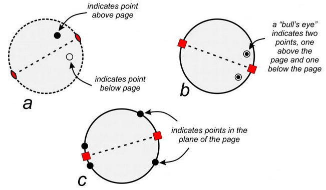
The stereo diagrams in Figure 10.18 show symmetry, and repetition of points, in the plane of the page quite nicely. However, symmetry operations also work in three dimensions. To accommodate the third dimension, we need a way to show points below and above the page. By convention, solid dots represent points above the plane of the page, and circles represent points below the plane of the page (Figure 10.20a). A bull’s-eye symbol, formed by a small circle around a dot, shows a point above the page that is directly above one below the page. Figure 10.20b shows two examples. Points within the plane of the page (around the equator of the crystal) always plot as solid dots on the outside circle of the stereo diagram (Figure 10.20c).
Figure 10.20a and b show a 2-fold and 4-fold axis of symmetry lying in (parallel to) the plane of the page. They operate on points above the page to produce points below. For the 2-fold axis, a black dot (above the page) becomes an open circle (below the page) after a rotation of 180o around the axis that lies in the plane of the page. The two symbols are not on top of each other. For the 4-fold axis (10.20b), 90o rotations around the axis (that is in the plane of the page) produce four equivalent points. The two points below the page are directly beneath the two points above, and so are shown as bull’s-eyes.
10.2.1.2 Mirror Planes
In Figure 10.20a, the outside circle is a dashed line. In the other two diagrams it is solid. Why the difference? A solid outside circle indicates that a horizontal mirror plane reflects points above the page to below the page (shown by the bull’s-eye symbol). In contrast, a dashed circle means there is no reflection and no mirror plane parallel to the page. In Figure 10.20c, the points are on the outside and, thus, within the plane of the page, and so cannot reflect up or down. In such cases, the circle could be solid or dashed but is generally shown solid.
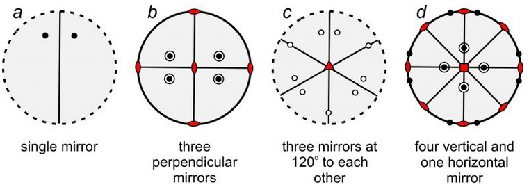
So, mirrors may lie in the plane of the page. They may also have other orientations. For example, the four stereo diagrams in Figure 10.21 include mirror planes that are perpendicular to the page. They appear as straight lines that pass through the centers of the diagrams. Some of these diagrams also depict other kinds of symmetry:
●Diagram a contains a single vertical mirror and two points related by reflection.
●Diagram b contains three mirrors at 90o to each other – one in the plane of the page (shown by the solid outer circle) and two vertical (shown by straight solid lines). It has a total of eight points – four above the page and four below. This diagram also contains three 2-fold rotation axes, shown by the red lens shapes.
●Diagram c contains three vertical mirrors (straight lines) at 120o to each other, with nine points (below the page) related by those mirrors. This diagram also contains a 3-fold rotation axis, shown by the red triangle at the diagram’s center.
●Diagram d has a horizontal mirror in the plane of the page (solid circle) and four other vertical mirrors (straight lines). It contains sixteen points related by the symmetry. This diagram also contains four 2-fold axes (lens shapes) and a 4-fold rotation axis (shown by the red square at the diagram’s center).
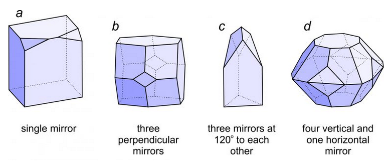
Figure 10.22 shows crystals with symmetries that match the four stereo diagrams in Figure 10.21. Crystal a has only a single mirror plane of symmetry. The right side reflects to the left side. Crystal b has three perpendicular mirror planes and three 2-fold axes. Each 2-fold axis is perpendicular to one of the mirrors. Crystal c has three mirrors that intersect at 120o this requires that a vertical 3-fold axis be present. Crystal d has four vertical and one horizontal mirror. It also contains four horizontal 2-fold axes and a vertical 4-fold axis.
10.2.1.3 Rotation Axes with Perpendicular Mirror Planes
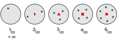
Many crystals, including some depicted in Figure 10.22, contain rotation axes that are perpendicular to mirror planes. Crystallographers use shorthand symbols to describe such combinations. We represent them by the symbols 1/m, 2/m, 3/m, 4/m, and 6/m. Figure 10.23 shows stereo diagrams for each. In these drawings, the mirror is horizontal and the rotation axis is vertical (perpendicular to the page). Note that the outer circles are solid in all these diagrams, because points above the page are reflected by a horizontal mirror to below the page. The symbol 1/m is somewhat redundant because the 1-fold rotation axis changes nothing. So, this symmetry is commonly just signified by m.
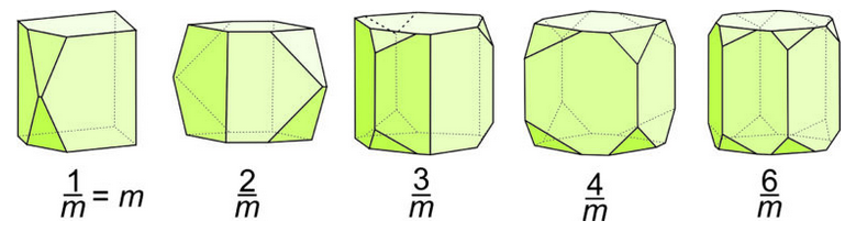
The crystal drawings in Figure 10.24 show crystals with symmetry equivalent to what we see in Figure 10.23. In all drawings, the top faces reflect to the bottom. Note that if these crystals did not have smallish scalene triangular faces, they would appear to have symmetry that included vertical mirror planes. They would look like simple prisms. These crystal shapes reinforce the idea that multiple faces with different shapes are sometimes needed to depict complex symmetry.
10.2.1.4 Rotoinversion Axes
In the discussions above, we talked about reflection, rotation, and inversion operations. Rotoinversion is a fourth, and an important, kind of symmetry operation. Rotoinversion, a combination of rotation and inversion, is a symmetry operation sometimes distinct from the others. The symbols 1, 2, 3, 4, and 6, represent rotoinversion axes. They are articulated as “bar-1,” “bar-2,” etc.
In a rotoinversion operation, we apply rotation and inversion sequentially. Just as with proper rotation axes, the angle of rotation is 360̊o for a 1-fold rotoinversion axis, 180̊o for a 2-fold rotoinversion axis, 120o for a 3-fold rotoinversion axis, etc. (table below.) The difference is that for rotoinversion, rotation of a point is followed by inverting it through the center of a diagram.
| rotoinversion axis | 1 | 2 | 3 | 4 | 6 |
| rotoinversion operation | rotate 360̊ and invert |
rotate 180̊ and invert |
rotate 120̊ and invert |
rotate 90̊ and invert |
rotate 60̊ and invert |
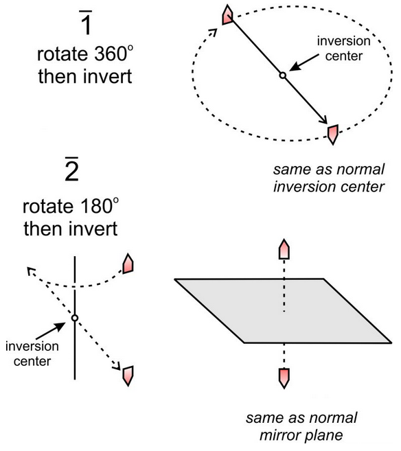
Figure 10.25 shows 1 and 2 rotoinversion operations applied to a single house-shaped motif. The 1 operation involves 360o rotation followed by inversion. This is the same as a normal inversion center.
The 2 operation involves 180o rotation followed by inversion. This is the same as reflection by a mirror plane. We include 1 and 2 operations in our list for completeness but recognize that they are redundant.
3 rotoinversion, however, is not so trivial. For example, in Figure 10.26 (below), we apply a 3 axis to solid point 1 (above the page). Rotation of 120o and inversion produces an open point (point 2, below the page). We repeat the operation: point 2 is rotated 120o and inverted to produce point 3, and so forth. After five repeats, we have produced points 2, 3, 4, 5, and 6, and we are done because a sixth repeat gets us back to the original point. A 3 axis relates six points in total, shown in the large stereo diagram in the Figure. Examination of this diagram reveals that a 3 axis is the same as a 3-fold axis and an inversion center operating independently. Three of the points are above the page and three below. Those above are not directly above those below – they are offset by a rotation of 60o.
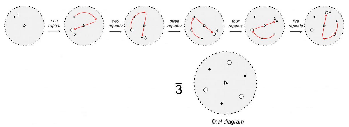
Figure 10.27, below, shows stereo diagrams for the different rotoinversion axes. Unlike 3, a 2, 4, or 6 operation is not equivalent to rotation and inversion operating separately, nor are they equivalent to proper 2-fold, 4-fold, or 6-fold rotation axes. But a 2 axis is equivalent to m; a 3 axis is equivalent to a 3-fold axis and an inversion center applied separately. A 6 axis is equivalent to a vertical 3-fold axis with a perpendicular mirror (in the plane of the page); it is equivalent to 3/m. Note that 4 rotoinversion is the only rotoinversion operation completely distinct from other symmetry operations. Although it is called a rotoinversion axis, crystals with 4 symmetry have neither a 4-fold rotation axis nor an inversion center.
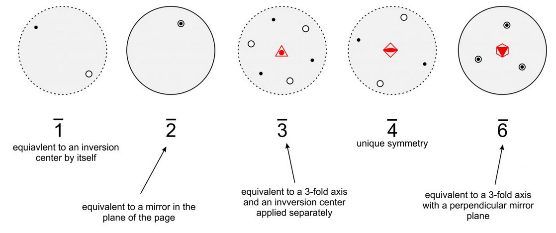
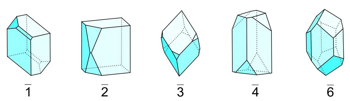
Figure 10.28 shows drawings of crystals with rotoinversion symmetry; they correspond to the stereo diagrams in Figure 10.27. Rotoinversion symmetry is often difficult to pick out in crystals and is more obvious in stereo diagrams.
Crystallographers rarely talk about 1 or 2 symmetry because it is simpler to talk about an inversion center or a mirror plane. References to 3, 4, and 6 are, however, normal, although we could describe two of them in other ways. The stereo diagrams in Figure 10.27 include (in red) the common symbols for 3, 4, and 6 at their centers.