
5.5: Drilling and Production Phase
- Page ID
- 15584

Permitting
A permit is required prior to beginning operations. Once a permit is issued, a company has one year to begin drilling or the permit expires. If drilling is begun but not completed within 16 months, the permit will expire. There are many stipulations for the permit application outlined in the Regulations for Oil and Gas Wells included in the 2012 Oil and Gas Act--Act 78 and 78a most recently amended in October, 2016. Act 78a specifically applies to unconventional (e.g. shale gas) wells.These stipulations include, but are not limited to, erosion and sediment control, protection of water supplies, surveys and identification of abandoned wells, handling of drill cuttings and fluids, and site restoration.
Source: Marcellus Center for Outreach and Research (MCOR), Penn State
Drillsite and Drilling Operations
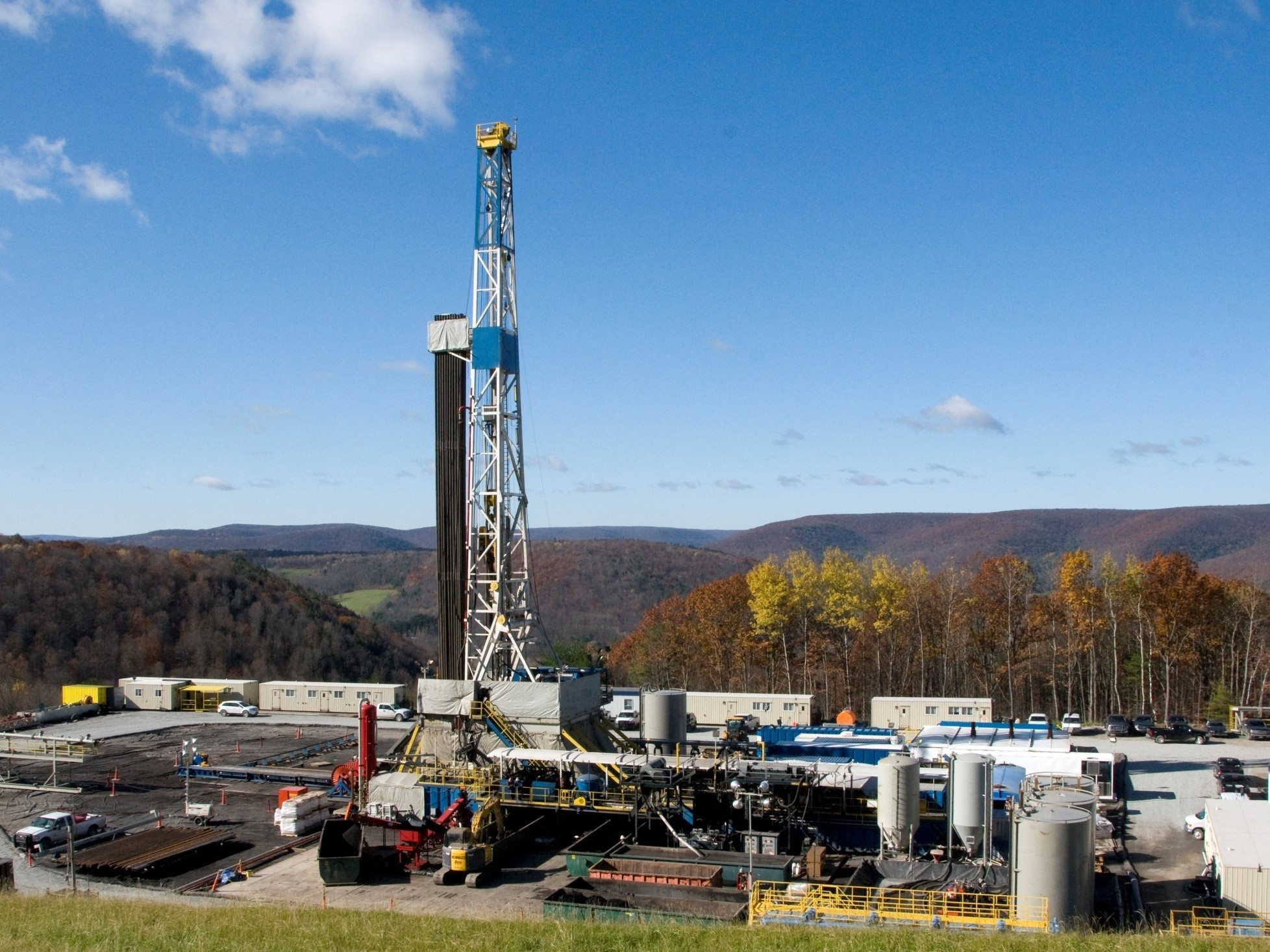
Most producing companies do not own or maintain their own drilling rigs and must lease rigs from a drilling or service company. For shale gas drilling in Pennsylvania, heavy duty rigs are required to handle long (heavy) drillstrings for deep drilling. These cost upwards of $250,000/day to lease and are usually top-drive rigs (Fig 5.5.1) that are capable of "walking" short distances in order to drill multiple holes on one pad (see 5.5.5). Drill pad arrangements and drilling rigs can be confusing to the uninitiated. There are many working parts with names (e.g., rathole,cathead, doghouse, etc.)and purposes that may seem obscure. But these are industry standard and many of them are designed for safety and containment of fluids and gases encountered downhole during the drilling operation.
Source: OSHA
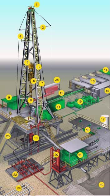
For a description of individual components, the reader should consult the illustrated glossary of typical drilling equipment at the drill site that can be found at OSHA (see Fig 5.5.2). A few of the key components will be discussed in the text as they relate to the drilling and completion of operations.
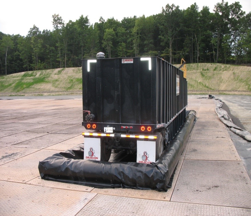
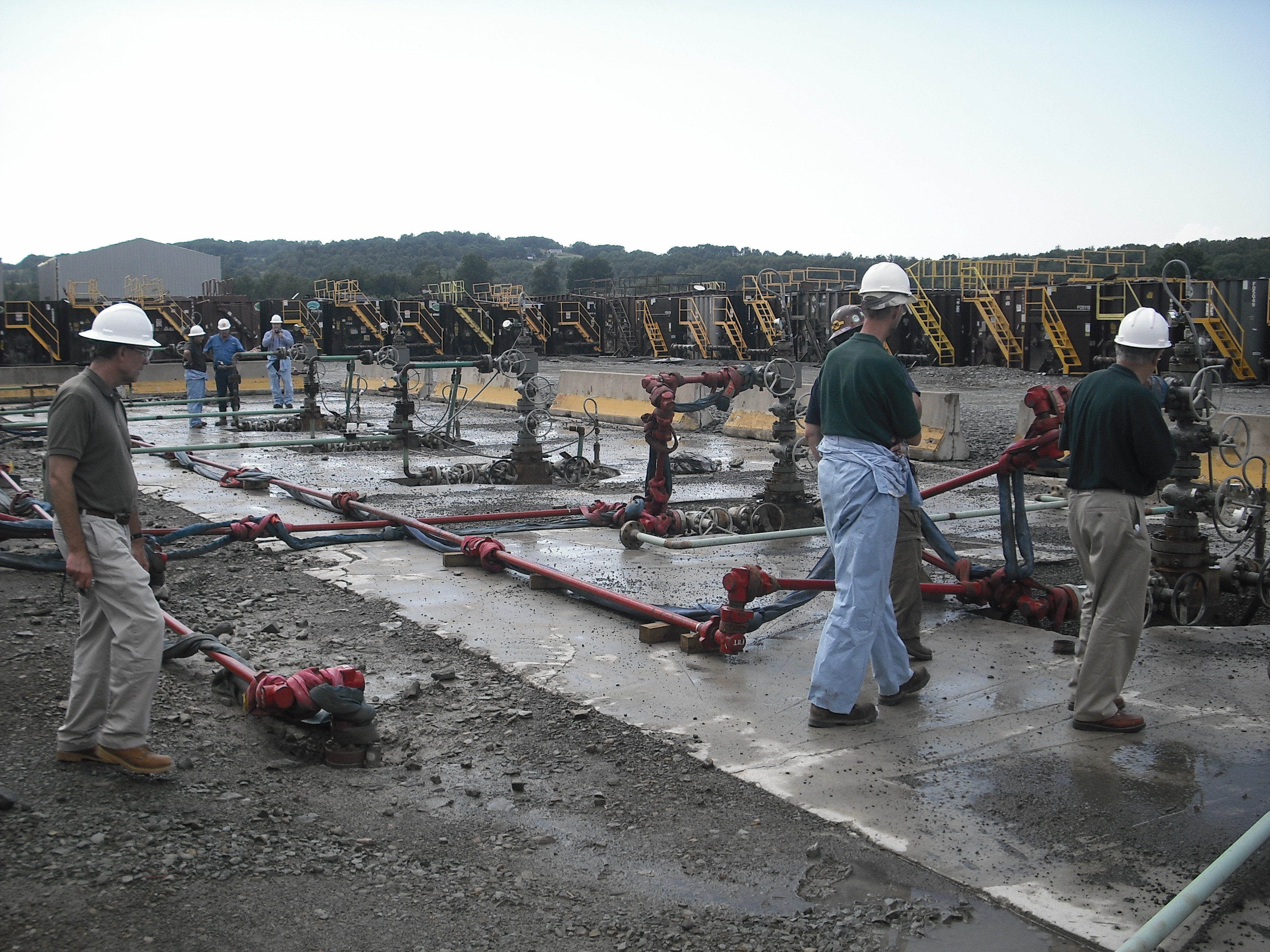
In order to prevent spilled fluids from penetrating into the ground, drillsites are protected by an impermeable pad with raised edges (Fig. 5.5.4). Even minor spills must be reported to PA DEP. Fluids flowing from the subsurface during drilling and post-drilling operations are stored temporarily in tanks on the pad. Storage in open, lined ponds was initially common practice but no longer used.
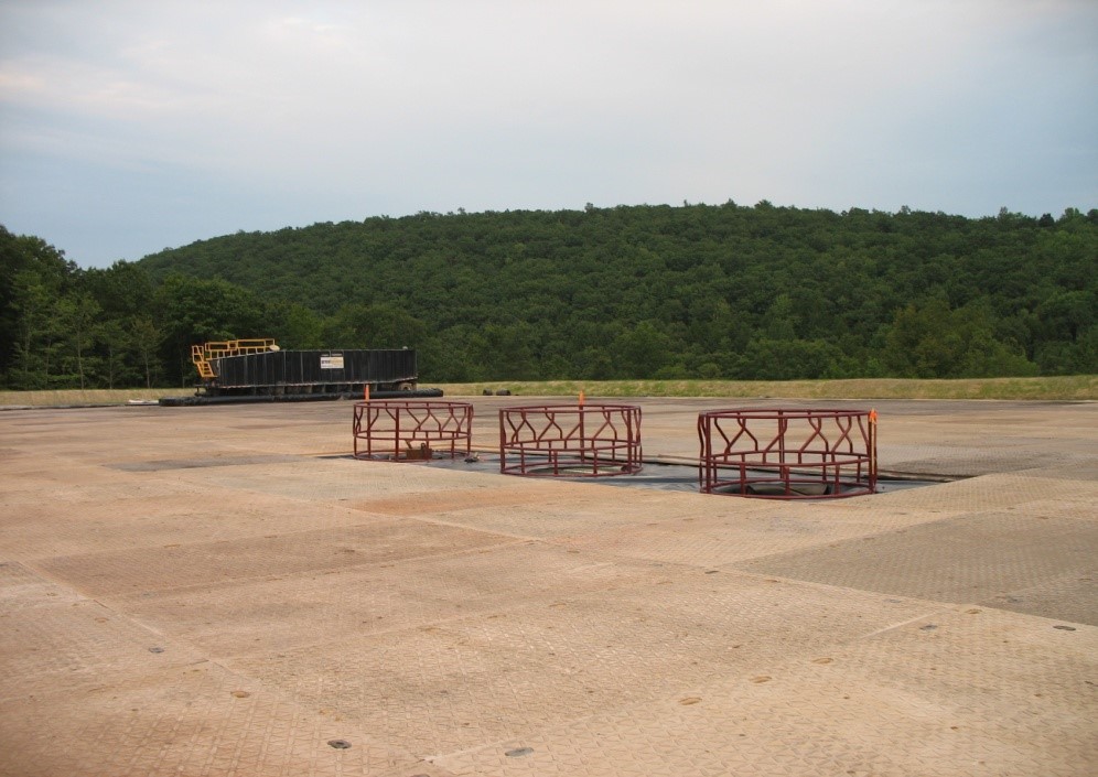
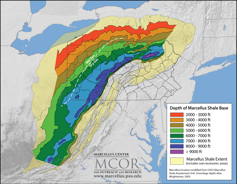
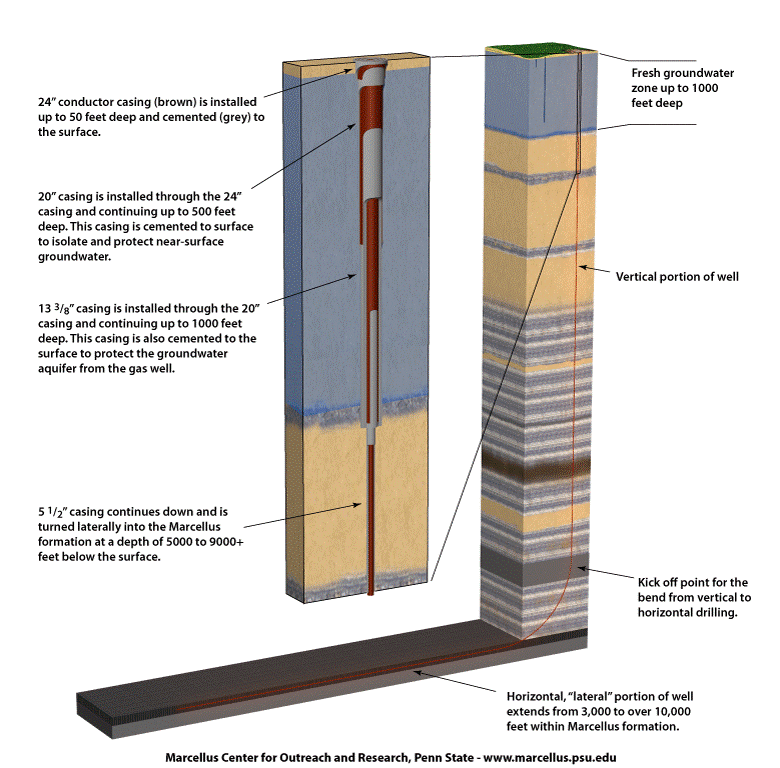
There is a geologic rationale to the layout of holes to be drilled on a drillsite. Figure 5.5.5 shows six completed wells on a former pad (now restored and covered with gravel). These producing wells are very close together at the surface and illustrate the position of the vertical parts of the wells by a drilling rig that can drill one well and "walk" a few feet to drill another. The Marcellus Shale horizon increases with depth towards the southeast from its shallowest level in northwestern Pennsylvania. (Fig. 5.5.6). Conventional vertical wells alone cannot tap sufficient hydrocarbons from this relatively thin shale unit to be economic. Thus, an unconventional strategy must be used that combine a vertical wellbore, drilled to about 1000 feet above the target horizon, followed by a bend and horizontal segment that is drilled along the target horizon; in this case, the target is typically the most organic-carbon-rich horizon near the base of the Marcellus Shale (Fig. 5.5.7). Note that the well is "cased" to protect groundwater resources from fluids and gases coming up the well from deeper horizons. Ultimately, most of the casing is cemented, particularly in the shallow zone of fresh water (typically from the surface to 500 to 1000 feet) to fill in the "annulus" (void space) around the casing and further protecting against contamination of shallower horizons by migrating fluids. We discuss this aspect further in a later section.
Source: Marcellus Center for Outreach and Research (MCOR), Penn State
Source: Marcellus Center for Outreach and Research (MCOR), Penn State
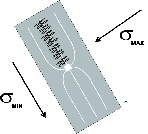
So, back to why the vertical wells are spaced and have the orientation that they do. Some time ago, Professor Terry Engelderat Penn State University showed that there are natural fractures in the subsurface within the Marcellus Shale that have a similar orientation across the Appalachian Basin. There are two major sets of fractures, which Dr. Engelder called J1 and J2. Examples of these intersecting fracture sets are shown in Figure 5.5.8. Without getting into the details of how these formed, suffice it to say that they are presently oriented relative to certain principal stress directions such that the J1 fractures, which are more closely spaced and oriented Northeast-southwest,will open somewhat if pressurized fluids are pumped along horizontal lengths of tubing placed perpendicular to them.This is the rationale for the pattern of drilling shown in Figure 5.5.9.
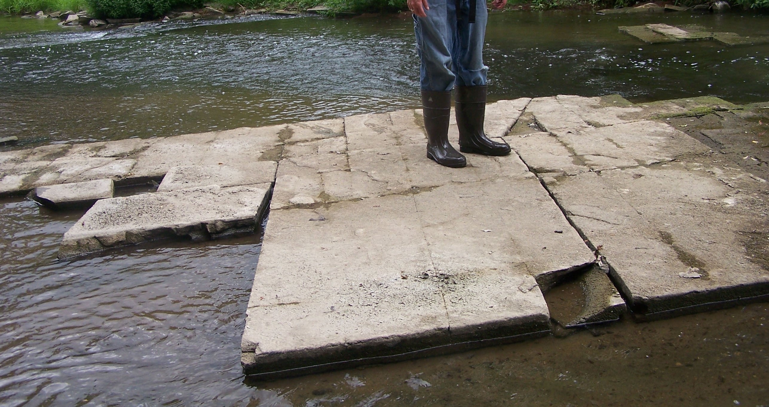
Photo courtesy of T. Engelder
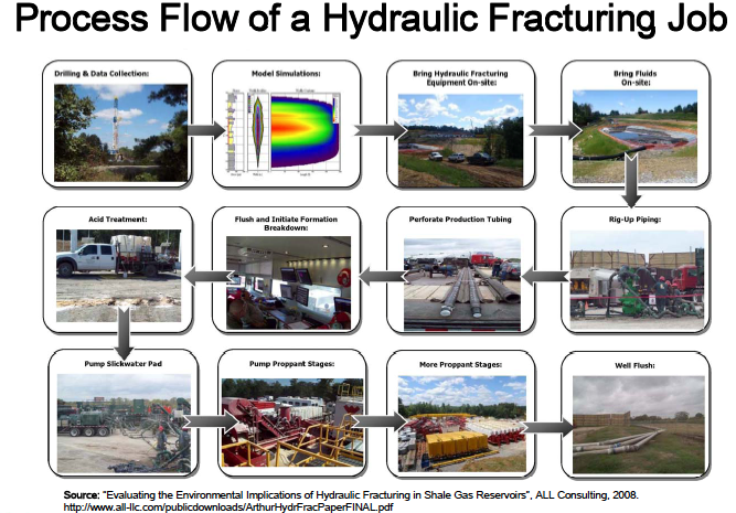
Source: "Evaluating the Environmental Implications of Hydraulic Fracturing in Shale Gas Reservoirs." ALL Consulting, 2008