
1.10: Fractures
- Page ID
- 12517

Introduction
Most of the structures we have dealt with so far in the course are products of ductile deformation, which is favoured by high temperature, high confining stress, low strain rates, and low rock strength. In contrast, fractures represent brittle failure of rocks in response to an applied differential stress. In general terms, fracturing is favoured by low values of pressure or mean stress, low temperatures (at which rocks are strongest), high strain rates, and strong or competent rocks such as well-cemented sandstones, limestones, and igneous intrusive rocks.
Fractures are planar or gently curved surfaces of failure produced by brittle failure of rocks. Where the rock masses on either side of a fracture have moved apart slightly, the fracture is called an extension fracture. If the two rock masses have slid past each other, the fractures are shear fractures. In the case of natural fractures, in the field, extension fractures are commonly called joints. Shear fractures are known as faults when the rocks on one side have been shifted significantly along the fracture surface. In this section we examine joints; later sections deal with faults.
Joints and veins in the Earth’s crust are of enormous importance to humans. Joints are planes of weakness in natural and artificial outcrops; failure along joint surfaces has led to catastrophic landslides and rock falls. In the subsurface, joints are pathways for the migration of fluids, including water, oil, and natural gas. An understanding of flow through fractures is necessary for the use of groundwater, and for the extraction of oil and natural gas. The space between the rock masses along a joint surface may become filled with minerals, deposited from groundwater, in which case the joint is known as a vein. Many economically important minerals are mined from veins.
Geometry of joints and veins
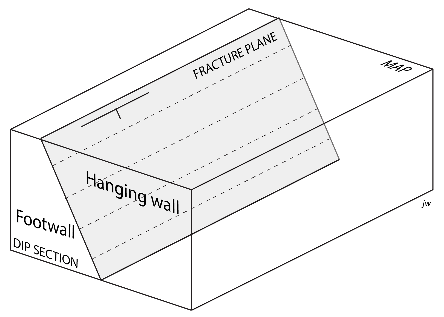
The orientation of a fracture, like any planar surface, can be defined by its strike and dip. At map scale the location and orientation can be represented by structure contours. The rocks immediately above a fracture constitute the hanging wall and those immediately below, the footwall (Figure 2). Such being the case, by definition the plane dips in the direction towards the hanging wall. Clearly, these terms have no meaning if the fracture is vertical, in which case the walls are better identified as ‘north wall’ or ‘southeast wall’, etc. depending on the strike.
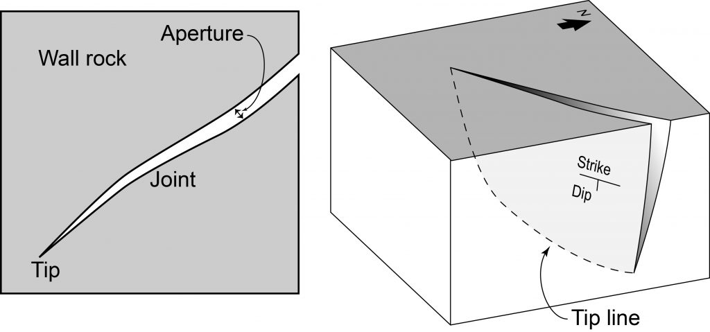
If there is space between the two walls of a fracture its width is known as the fracture aperture. Some fractures show constant aperture over large distances, but in most there is some variation. Fractures do not extend forever through the Earth’s crust. The point at which the trace of a fracture ends is known as a fracture tip. In three dimensions, the tip of a fracture is a linear feature, known as a tip line.
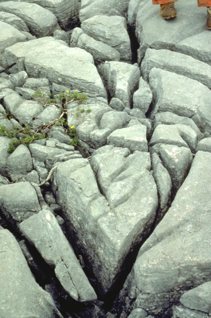
Joints are very common in many outcrops, but their orientations are typically not random. It is common to observe many joints in approximately the same orientation. These are known as a joint set.
A combination of joint sets, cross-cutting each other in a regular way, is known as a joint system.
Features of joint surfaces
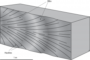
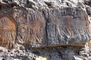
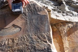
Joint surfaces may be perfectly planar, but in many cases they show feather-like markings known as plumose or plume structure.
Typical plume structure consists of two parts. A pattern of feather-like striations, called hackles radiates from a central point or line, while a bolder series of concentric bands, known as ribs is approximately perpendicular to the hackles. Towards the tip of a joint, in what is known as the fringe area, it is common to see that the surface splits into a number of smaller surfaces arranged like the blades of a fan. Each of the blades may have its own plume structure.
Plume structure can be simulated in laboratory experiments. It records the process of fracture propagation, and the dynamics of the fracture tip.
Fracture propagation is the process whereby a fracture grows within a rock, and involves the outward migration of the fracture tip. Fracture propagation may be very fast: speeds up to those typical of seismic waves (a few kilometres per second) are possible.
Because the fracture tip at any moment is the boundary between unfractured rock and rock that has been weakened by fracturing, the orientations of the stress axes are modified in the vicinity of the tip. This in turn causes the variations in fracture orientation as the fracture propagates.
The kinematics of fracture propagation may be interpreted from plume structure. Hackles diverge in the direction of propagation, while concentric ribs mark successive pauses in the position of the fracture tip.
Features of vein fills
Two contrasting types of vein fills are common.
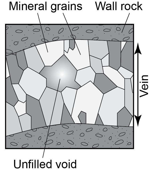
When a joint aperture has been held open by fluid pressure during hydrothermal activity, mineral crystals may be deposited on the walls, producing a vein. Crystals that grow into the fluid-filled spaces may be euhedral (showing clear crystal surfaces) but more typically the crystals run into one another producing compromise boundaries that are also approximately planar. There is often a tendency for crystals to get larger towards the centre of a vein.
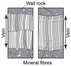
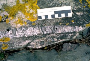
Alternatively, when a joint has been filled by minerals deposited as the fracture opened, fibrous fills may be produced. Typically a very narrow crack is filled by a first layer of crystals. This is followed by renewed opening, and deposition of more mineral material and so on. This process is known as crack-seal. The result is that a series of fibres crosses the vein. The fibres track the kinematic process of vein opening.
There are actually two different styles of fibre fills that can be found in veins. If the repeated cracking occurs in the centre of the vein, the fibres are typically in crystallographic continuity with the grains in the wall. Such veins are described as syntaxial. Sometimes in cross-sections of syntaxial veins it’s possible to pick out the line of separation running along the centre. In contrast, if the repeated cracking occurs at the edge, then the vein is antitaxial. In antitaxial veins there is typically no single centre line, but there may be multiple strands of wall-rock inclusions parallel to the walls of the vein, marking successive cracks.
Dynamic interpretation of fractures
There are some characteristic relationships between the orientation of fractures and the stress axes that give us useful information.
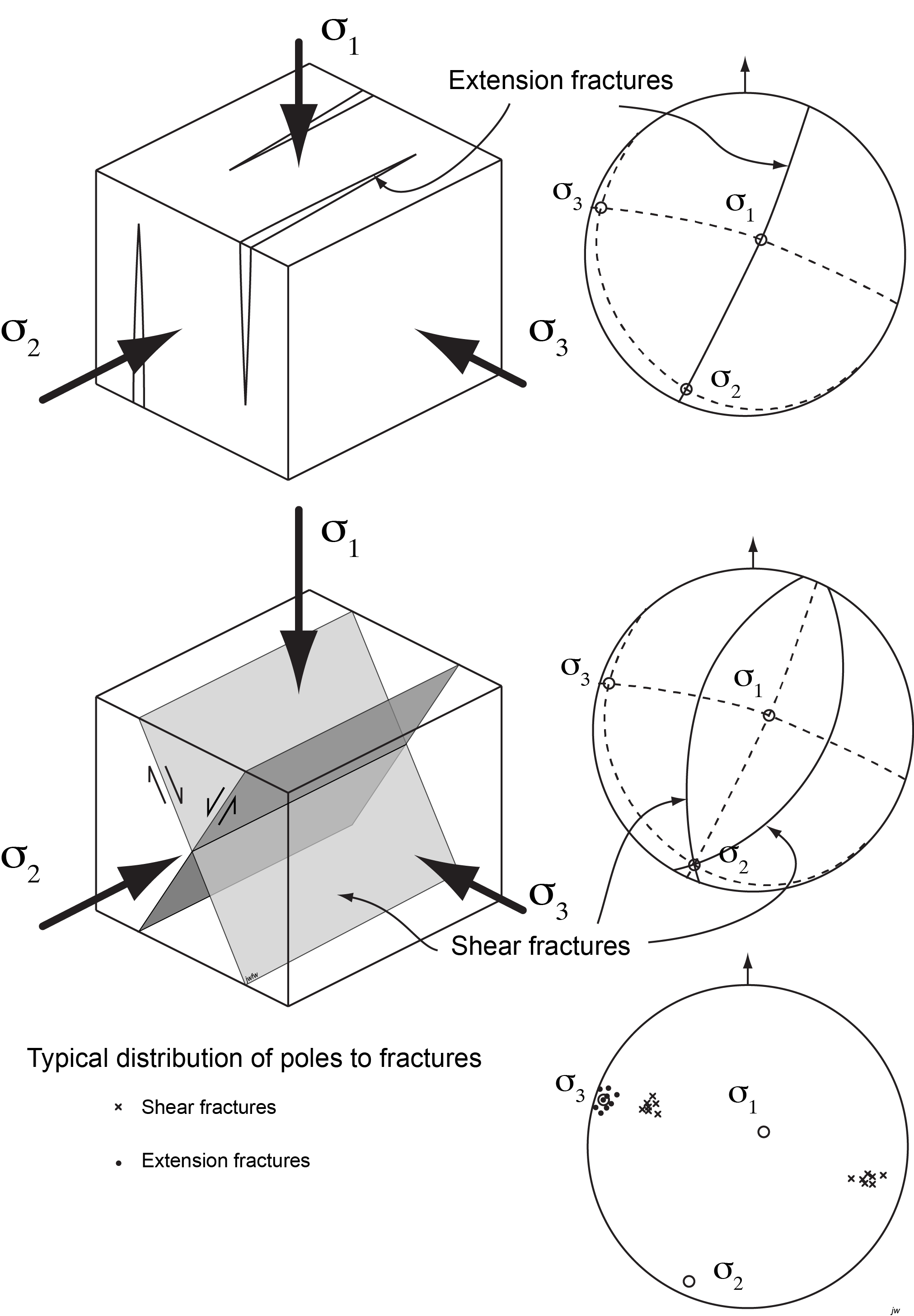
Extension fractures
Where rocks have been fractured at low mean stress (or ‘confining pressure’), it is likely to be broken along fractures perpendicular to σ3. If we examine the fractures, we find that they are extension fractures: the two sides of the fracture have been pulled apart.
Conjugate shear fractures
At higher pressure, failure typically occurs along two families of planes, breaking rocks into wedge-shaped fragments. The angle between the two families is about 60°. The planes intersect each other in a line parallel to σ2. The maximum principal stress σ1 bisects the acute angle between the planes, and the minimum stress σ3 bisects the obtuse angle.
If we examine the fractures, we find that they are shear fractures: the two sides of the fracture have slid past each other. The sense of shear is such that the acute angles at the edges of the fragments have been pushed inward. Movement is inwards along the σ1 direction and outward along σ3.
Common types of joint and vein systems
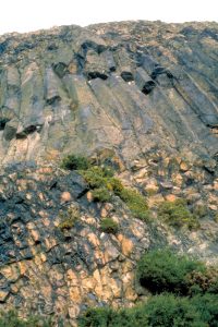
Primary joints in igneous rocks
Primary joints in igneous rocks are typically the result of contraction during cooling from magmatic temperatures. Most such joints form perpendicular to the surfaces of lava flows or to the contacts of intrusions. In tabular igneous bodies such as lava flows, sills, and dykes, the joints may have a columnar appearance and may show a strikingly regular pattern of polygons, mainly hexagons, in cross-section. It has been shown that for a given amount of contraction, a hexagonal pattern minimizes the work in forming new surfaces.
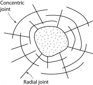
Joints in the host rock of intrusions
Joints are also common outside igneous intrusions. Two types are common: radial joints and concentric joints. These joints are typically the result of extension either during the forceful intrusion of magma or during the subsequent differential cooling of the intrusion.
Joints related to erosion and exhumation
It’s common for joint sets to form parallel to the topographic surface in areas that have undergone rapid erosion. These are known as sheeting or sheet joints, and the process is known as exfoliation. These joints are most conspicuous in intrusive igneous rocks like granite, which are otherwise typically isotropic. In extreme cases, granite with many sheet joints may be confused with a bedded sedimentary rock when viewed from a distance!
There are several possible causes of exfoliation.
- In regions where the crust is in horizontal compression, σ3 is vertical. As overburden is removed by erosion, and the mean stress is reduced, σ3 becomes negative (tensile). The rock tends to expand upward and does so by forming roughly horizontal joints.
- Secondly, residual stresses may be locked into rocks at the time of formation, particularly during the cooling of intrusions. If tensile stresses are perpendicular to contacts, these may lead to the formation of joints parallel to the contacts when erosion reduces the overall pressure.
- Finally, weathering of igneous rocks leads to significant volume changes, as water is absorbed, and clay minerals form. These volume changes may set up stresses that encourage exfoliation behaviour.
Joints related to faults and shear zones
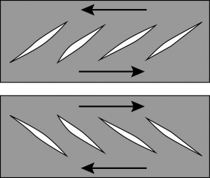
Faults and shear zones are typically associated with high densities of joints and other fractures. One common geometry reflects the distribution of stress in a developing fault zone. Repeated joints or veins are oriented at an angle of about 45° to a developing fault in a configuration called en echelon (derived from a diagonal military formation). The joints or veins are formed by extension, and are oriented perpendicular to σ3.
Joints related to folds
In folded layered rocks, particularly sedimentary rocks that were close to the brittle-ductile transition when they were folded, complex joint patterns may be present. Most common are radial joints that are parallel to fold hinges and roughly perpendicular to layers. They are most common on the outside parts of buckled competent layers, and probably form in response to stretching of the outer arc of the layer during folding.
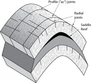
A second set of joints is sometimes found parallel to the folded layers, occurring particularly at the inner surfaces of buckled competent layers. These probably result where the incompetent layers are insufficiently ductile to fill the space in the hinges between competent layers. Veins in this position have been particularly prominent sources of gold in several goldfields, notably in Australia and in Nova Scotia, where they are known as saddle reef veins.
A third type of fold-related veins occurs parallel to the profile plane of folds. Logically these are called profile veins but they are also often called ac-veins, from an older terminology for folds, involving three “axes” a, b and c. (What we now call the fold axis was axis b in this system). Profile joints and veins indicate that a component of extension occurred along the length of the fold hinges.