1.4: Stereographic Projection
- Page ID
- 12507

Introduction
Stereographic projection is a powerful method for solving geometric problems in structural geology. Unlike structure contouring and other map-based techniques, it preserves only the orientation of lines and planes with no ability to preserve position relationships. However, it is extremely useful, as orientation problems are very common in structural geology. Stereographic projection has been in use since the second century B.C. and is a popular method used by crystallographers as a tool for representing crystal form. However, there is one important difference. Whereas crystallographers use an upper hemisphere projection, structural geologists always use the lower hemisphere. There is a good reason for this: the lower hemisphere represents the region beneath the Earth’s surface where the rocks have not yet been eroded away. However, if you have already met the stereographic projection in mineralogy, the lower hemisphere may take a little getting used to. Try to imagine that you are looking down into a bowl-shaped depression in the Earth’s surface. The on-line visualization tool at https://app.visiblegeology.com/stereonet.html may also help.
Stereogram basics
There are two parts to any stereographic projection. The projection itself, or stereogram, is usually drawn on tracing paper, and represents a bowl-shaped surface embedded in the Earth. The stereographic net or stereonet is the 3-D equivalent of a protractor. It is used to measure angles on the projection. To measure angles, we need to rotate the net relative to the tracing paper. For practical reasons we usually turn the tracing paper and keep the net fixed, but it is important to remember that in reality, the projection has a fixed orientation and the net should be rotated to make measurements.
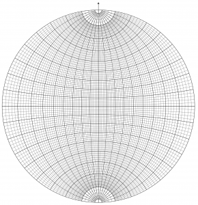
To construct a stereogram, take a sheet of tracing paper and draw a circle, with the same radius as an available stereonet. This circle is known as the primitive. Mark the centre with a cross, and mark a north arrow on the primitive at the top of the page. Mark E, S and W (or 090, 180 and 270) points at 90° intervals around the primitive. It is sometimes helpful to reinforce the centre with adhesive tape on the back of the tracing paper.
The stereonet may be reinforced with card to extend its life. It is convenient to place an old-fashioned thumb tack through the centre of the net. Protect yourself and others from the thumb tack by keeping it embedded in an eraser while not in use. There are several varieties of stereonet available. We will start with a Wulff net, which is used for the construction of the true, or equal-angle stereographic projection. In later labs we will use a Schmidt net, which constructs an equal-area projection.
Principle of stereographic projection
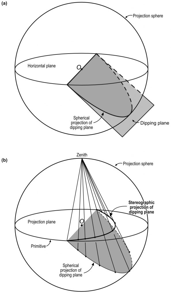
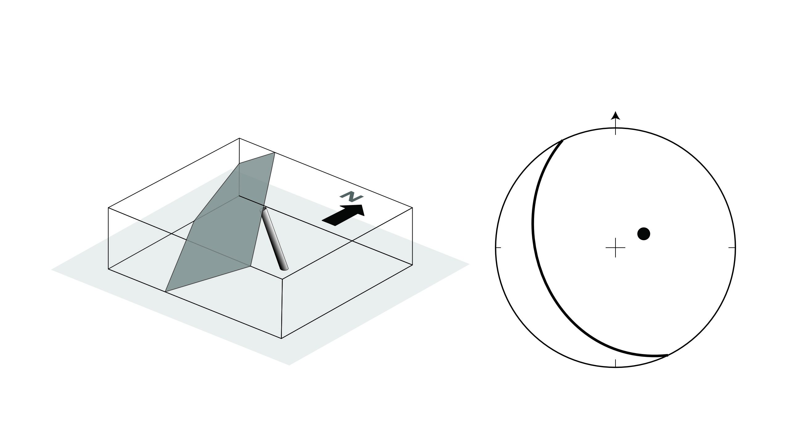
For stereographic projection, a line or a plane is imagined to be surrounded by a projection sphere (Fig. 1a). A plane intersects the sphere in a trace that is a great circle that bisects the sphere precisely. A line intersects the sphere in a point. To image features on a sheet of paper, these traces and points are projected from a point at the summit or zenith of the sphere onto the equatorial plane. This is clearer in a diagram (Fig. 2b), which shows the method for stereographic projection of a dipping plane. A family of planes dipping at various increments is shown in Fig. 3a. Planes project as curves that are actually perfectly circular arcs called cyclographic traces or just great circles. Lines project as points also known as poles.
As a general principle, planes that dip at low angles are represented by great circles having significant curvature and lying closer to the primitive, whereas steeply dipping planes are characterized by straighter great circles passing close to the centre of the plot. All vertical planes will project as straight lines passing through the centre of the stereogram.
Sometimes we represent a plane by its pole. The pole to a plane is the plot of a line perpendicular to the plane. For a horizontal plane the pole is in the centre of the net. Gently dipping planes have poles near the centre; steeply dipping planes have poles near the edge. The pole is always in the opposite quadrant to the great circle. Poles are used when plotting numerous great circles would make the plot cluttered and confusing.
Features of the net
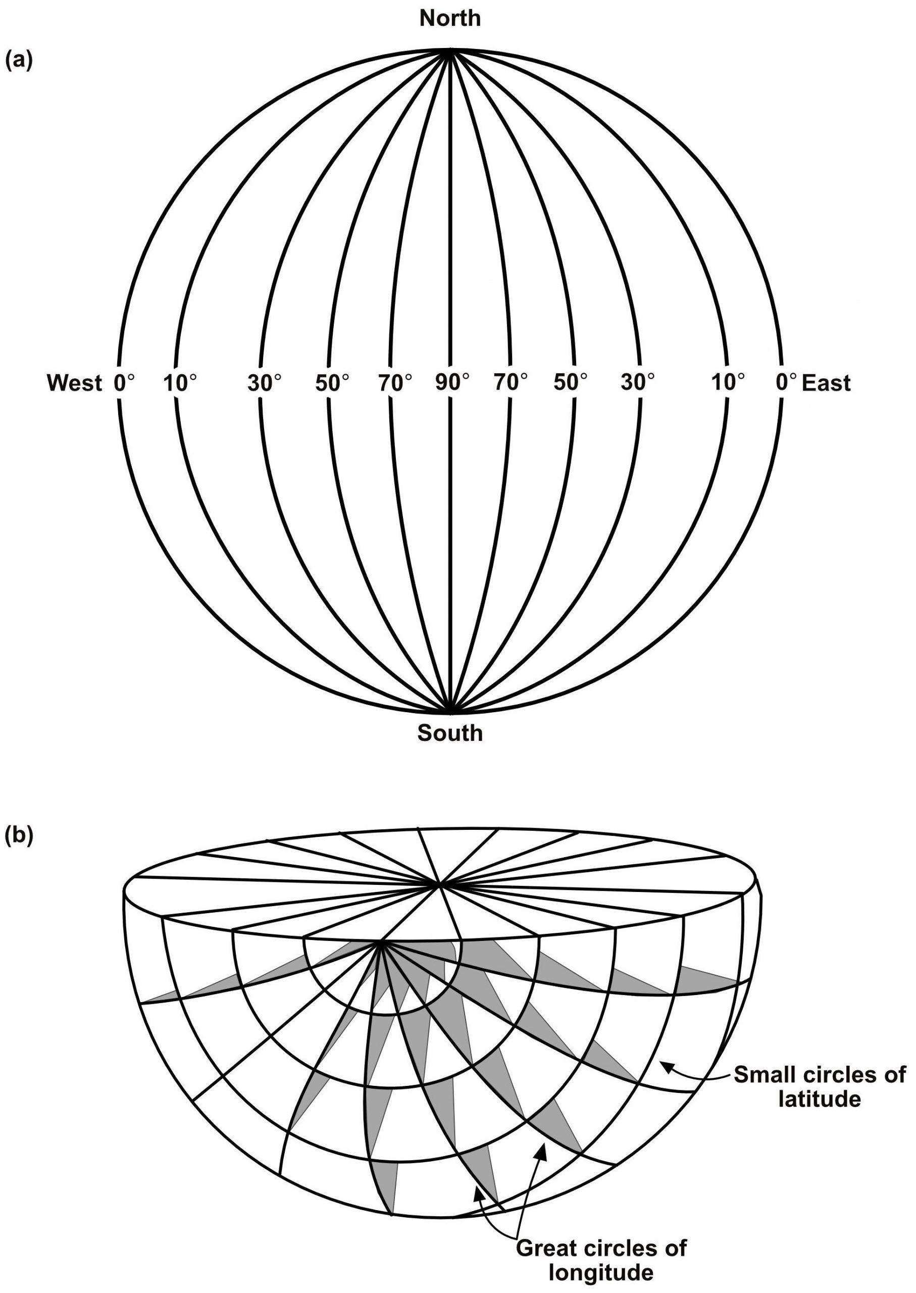
The stereographic net assists in the construction of great circles and points. It contains a family of great circles intersecting at the top and bottom points of the net (Fig. 3a). Every fifth cyclographic trace is bolder so that ten degree increments can be easily counted. By rotating the net, a great circle can be maneuvered into any desired strike and dip orientation. The net also contains small circles (Fig. 3b) that are helpful in solving rotation problems, and act as a scale of pitch angles along each great circle.
One great circle on the net corresponds to a vertical plane and is straight. It runs from top to bottom of the net. One trace in the family of small circles is also straight, from left to right on the net; it is actually a great circle too. These two intersecting lines form four straight radii which are crucial for counting angles of dip and plunge.
When the plot is located so that its north arrow coincides with the top of the net, it is said to be in the reference position.
Two applications of the stereographic projection
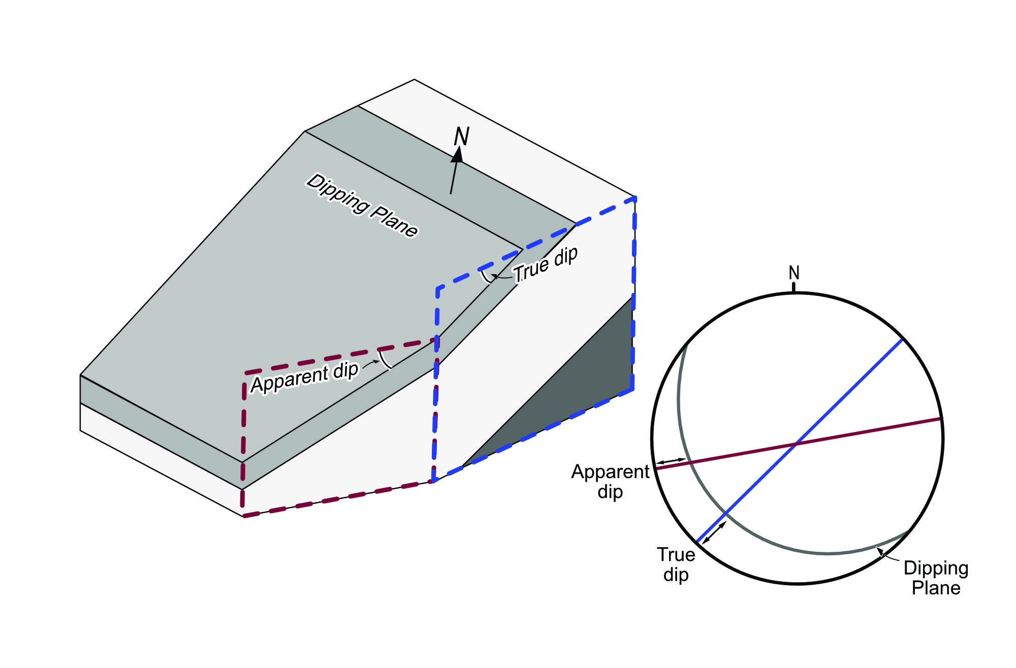
True and apparent dip
In lab 2 you encountered the terms ‘true dip’ and ‘apparent dip’. Refer back to lab 2 if you need to remind yourself of the difference. In principle, it’s possible to make conversions between true and apparent dip by trigonometry. However, it’s generally much easier to make the conversion using the stereographic projection. The construction is shown in Fig. 5.
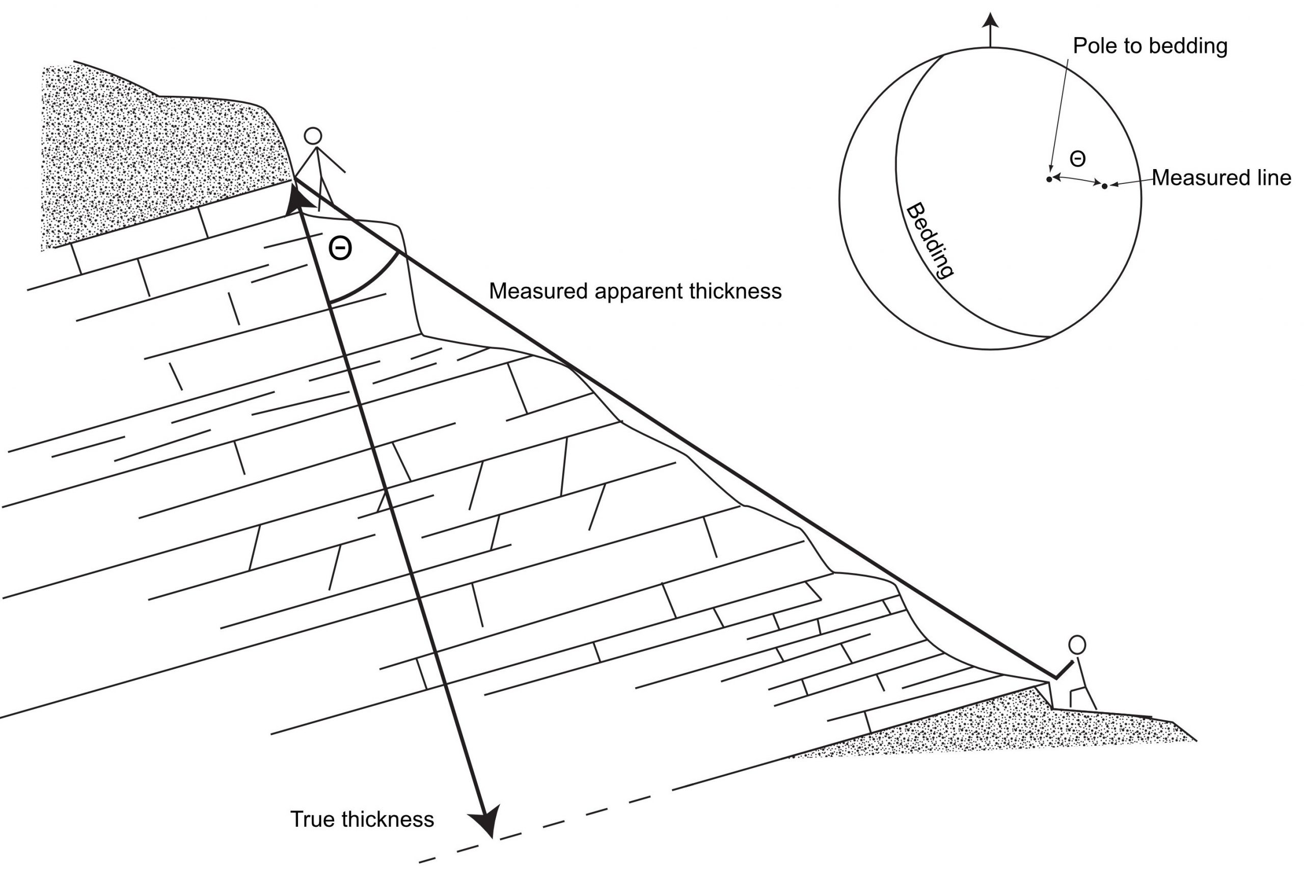
True and apparent thickness
A common problem in stratigraphy is to determine the true thickness of a formation. True thickness is measured perpendicular to the plane of bedding. Often, in the field or in a subsurface well, an apparent thickness is measured – one that is oblique to bedding, and therefore overestimates the true thickness (Fig. 6). There are many trigonometric methods for calculating true thickness, depending on the exact circumstances of measurement. However, one method using the stereographic projection works every time: multiply the apparent thickness by the cosine of the angle (θ) between the pole to bedding and the line of measurement (the trend and plunge of the traverse, tape measure, or whatever measuring device was used).
True thickness = Measured thickness × cos(θ)