
22.3: Ice Crystal Optics
- Page ID
- 10196

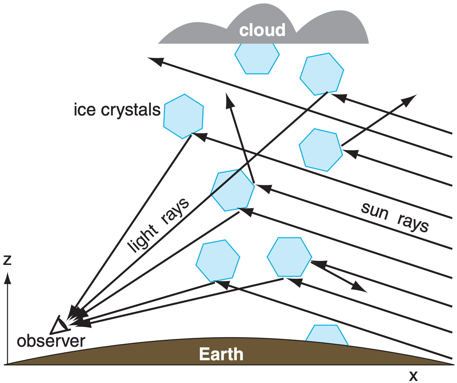
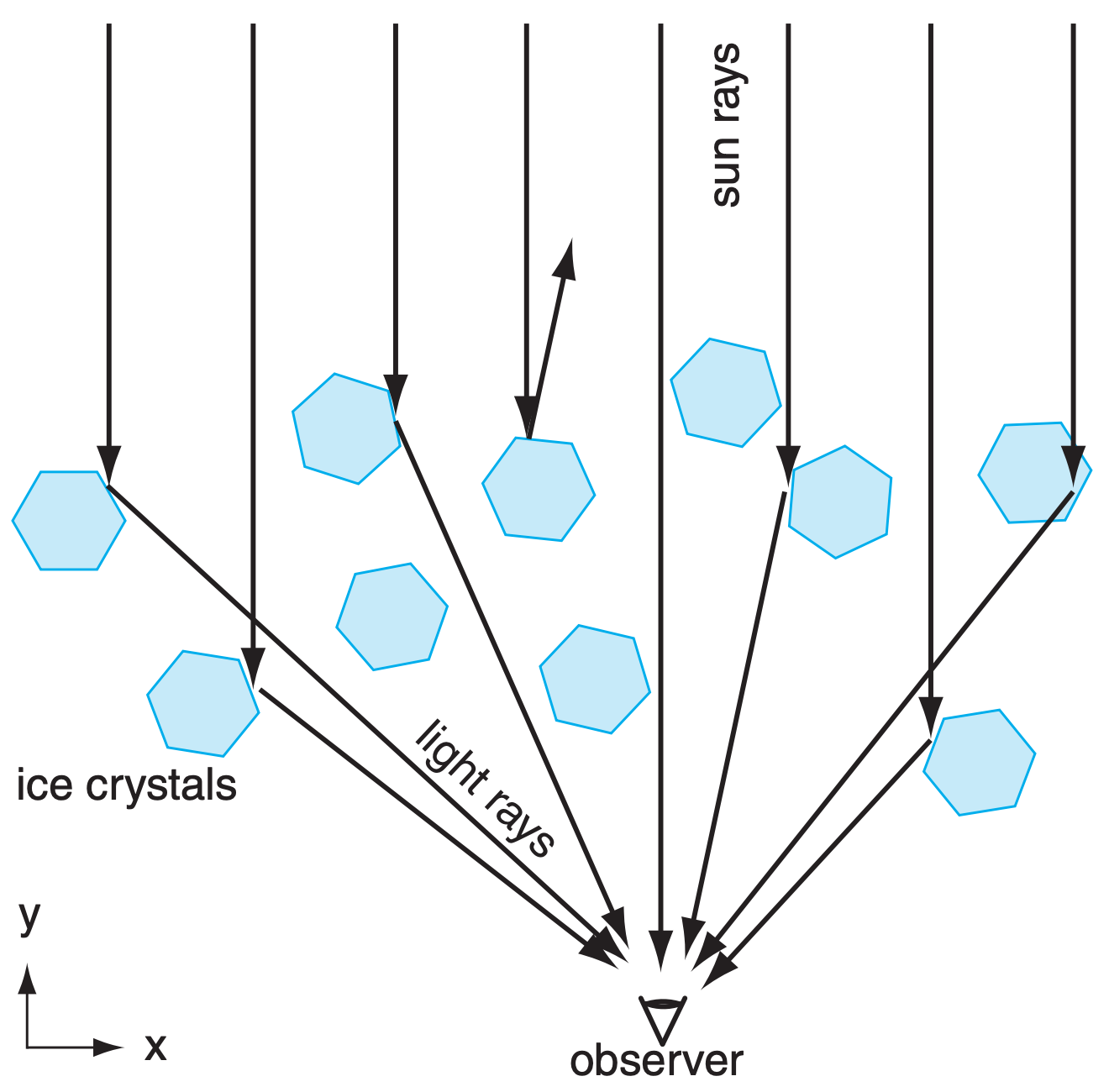
Most of the common ice-crystal optical phenomena are seen by looking more-or-less toward the sun (Fig. 22.16). To observe them, shield your eyes from the direct rays of the sun to avoid blinding yourself. Also, wear sunglasses so your eyes are not dazzled by the bright sky close to the sun.
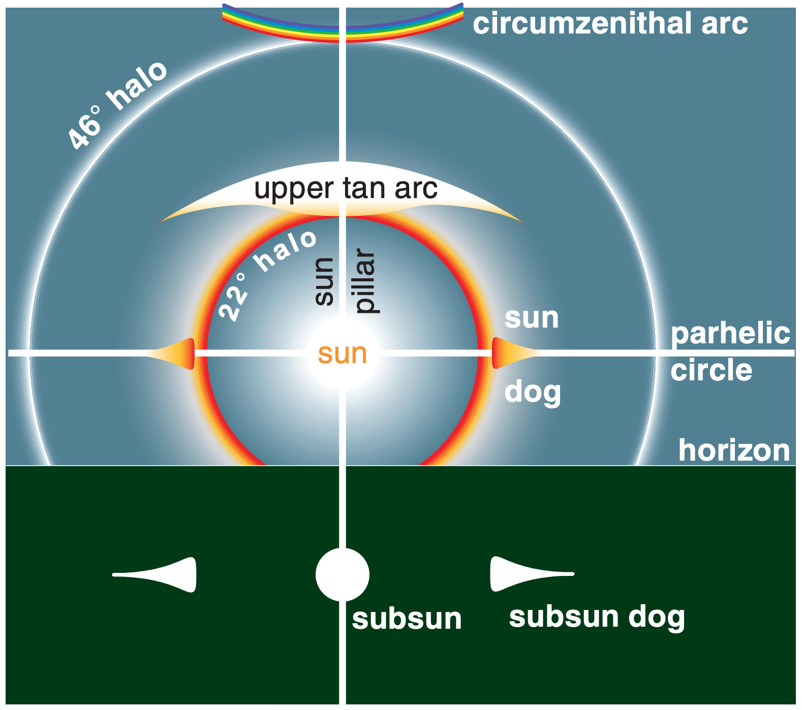
Subsuns, sun pillars, and parhelic circles are caused by simple reflection from the outside surface of ice crystals. Reflections from inside the ice crystal can also contribute to the intensity of these phenomena.
Sundogs, halos, circumzenithal arcs, and tangent arcs are caused by refraction through the ice crystals, with the red color closest to the sun.
Subsun dogs are caused by both refraction and reflection in the ice. There are many other optical phenomena related to ice crystals, only a few of which we cover here.
Ice crystals (types of snow) can form as high-altitude cirrus clouds, can be naturally seeded within and fall from the base of mid-altitude water-droplet clouds, can grow within low- or mid-altitude cloudless cold air of high relative humidity, or can be stirred up by the wind from fresh surface snow. For all these situations, the best optical displays occur with a diffuse concentration of crystals in the air. Namely, the air looks mostly or partially clear, except for sparkles of light reflected from the sparsely spaced crystals (nicknamed diamond dust).
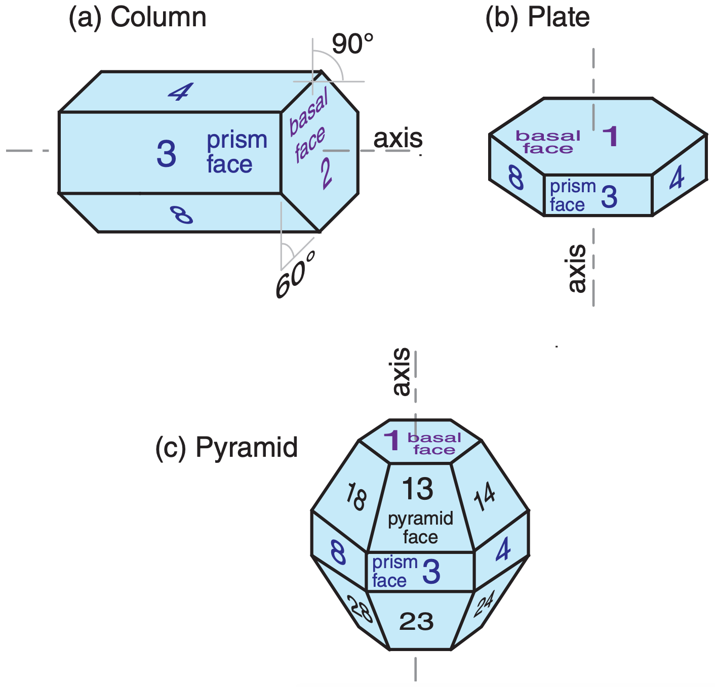
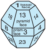
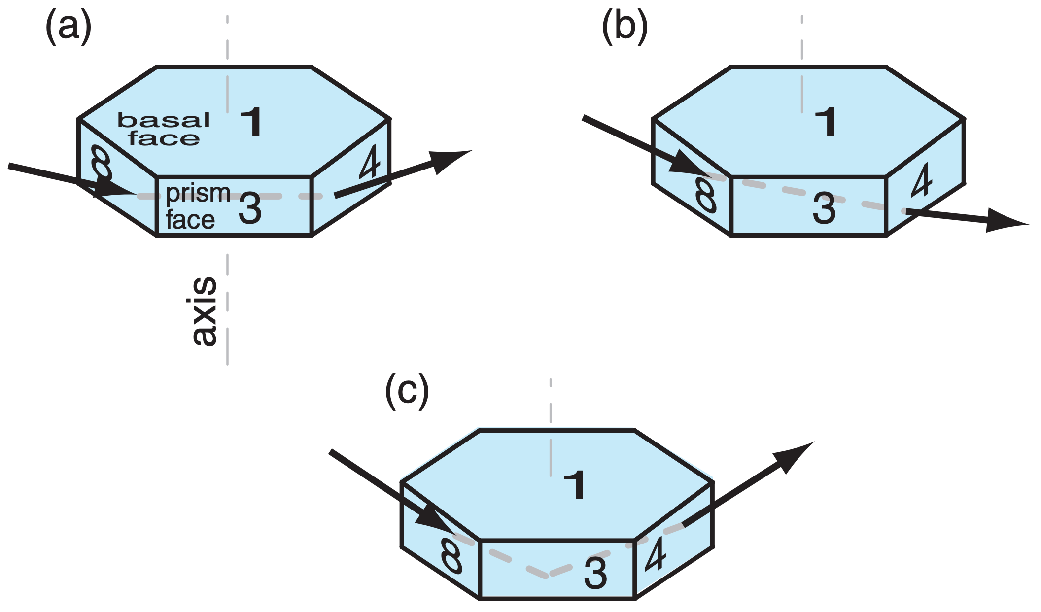
The crystals have a variety of shapes, most with hexagonal cross-section (see Figs. 7.12 and 7.13 in the Precipitation chapter). The two shapes most important for atmospheric optical phenomena are the hexagonal column and hexagonal plate (Fig. 22.17). The plate is just a very short column. Hexagonal pyramid-capped columns cause rarer halos.
Plates or columns, if larger than about 30 µm, gently fall through the air with the orientation relative to horizontal as sketched in Fig. 22.17. Namely, the crystal axis of large columns is nearly parallel to the ground, and the axis of large plates is nearly vertical. Surprisingly, this natural orientation is associated with relatively high aerodynamic drag on the falling crystal. Smaller crystals tend to tumble as they fall, giving random orientations.
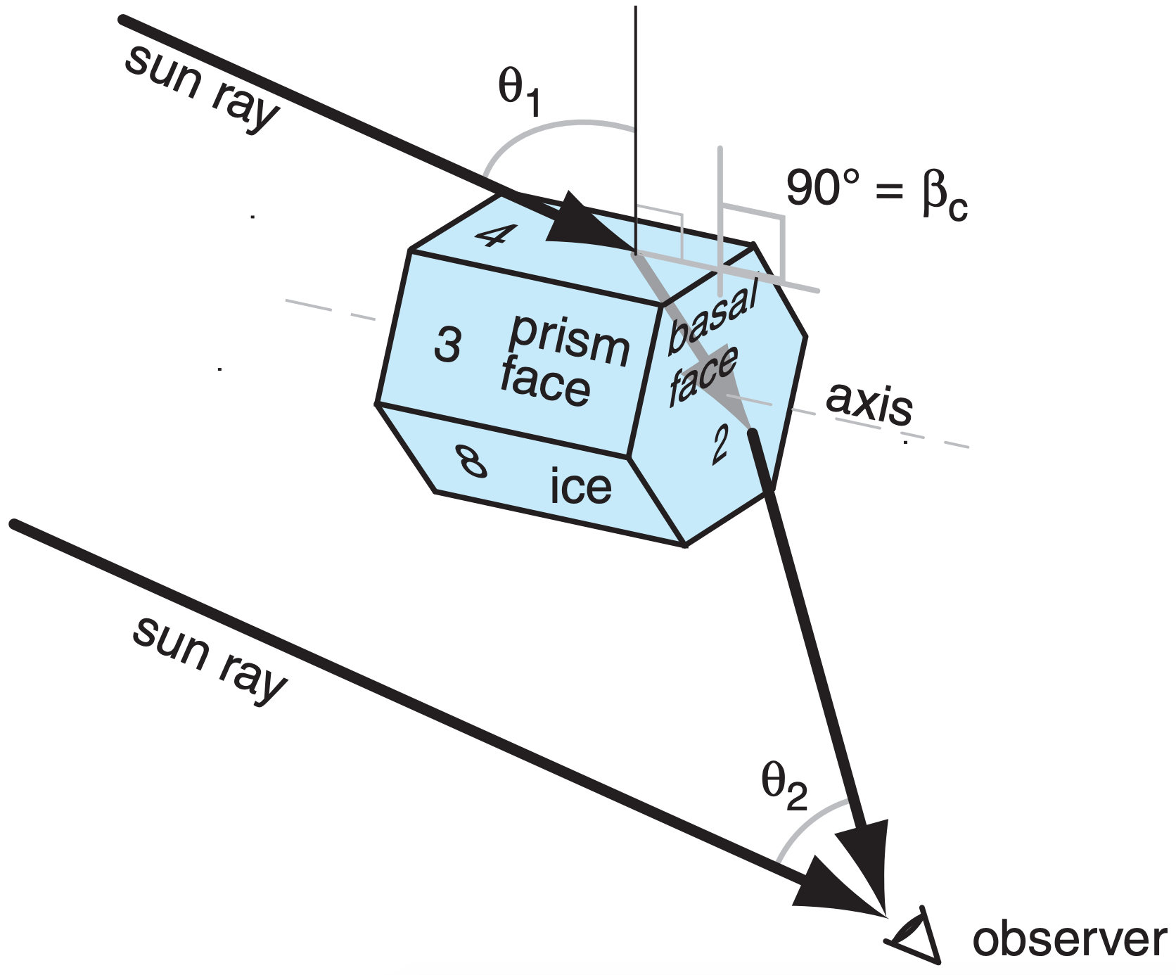
Crystal faces are numbered as shown in Fig. 22.17, where basal faces numbered 1 and 2 mark the ends of the hexagonal column, and prism faces 3 - 8 wrap sequentially around the sides. In naming the relative positions of prism faces: 4 and 3 are examples of adjacent faces, 4 and 8 are alternate faces, while 4 and 7 are opposite faces. Pyramid faces are numbered as double digits, where the first digit indicates the number of the adjacent basal face, and the second digit indicates the number of the adjacent prism face. The numbering is useful to track ray paths.
As shown in Fig. 22.17, the most important wedge angles (βc) of plate and column crystals are 60° (such as between faces 3 and 7, or 4 and 8) and 90° (such as between faces 3 and 1, or between 4 and 2). Angles for pyramids are discussed later.
22.3.1. Sun Pillar
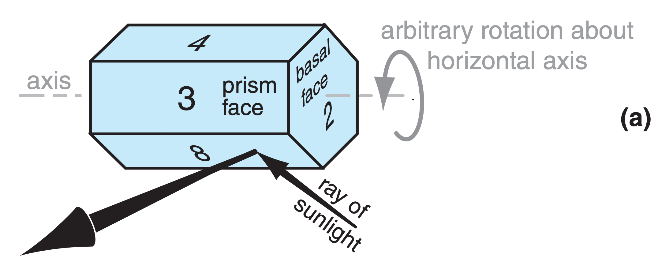
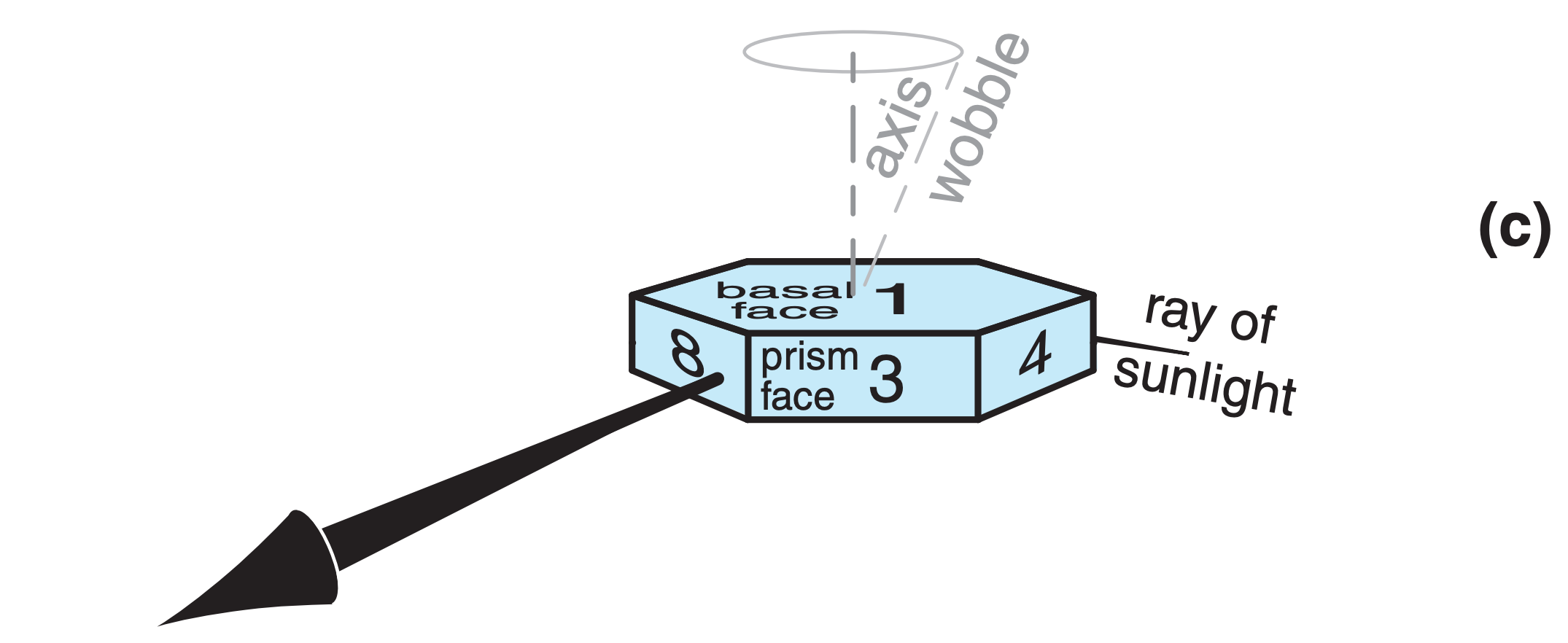
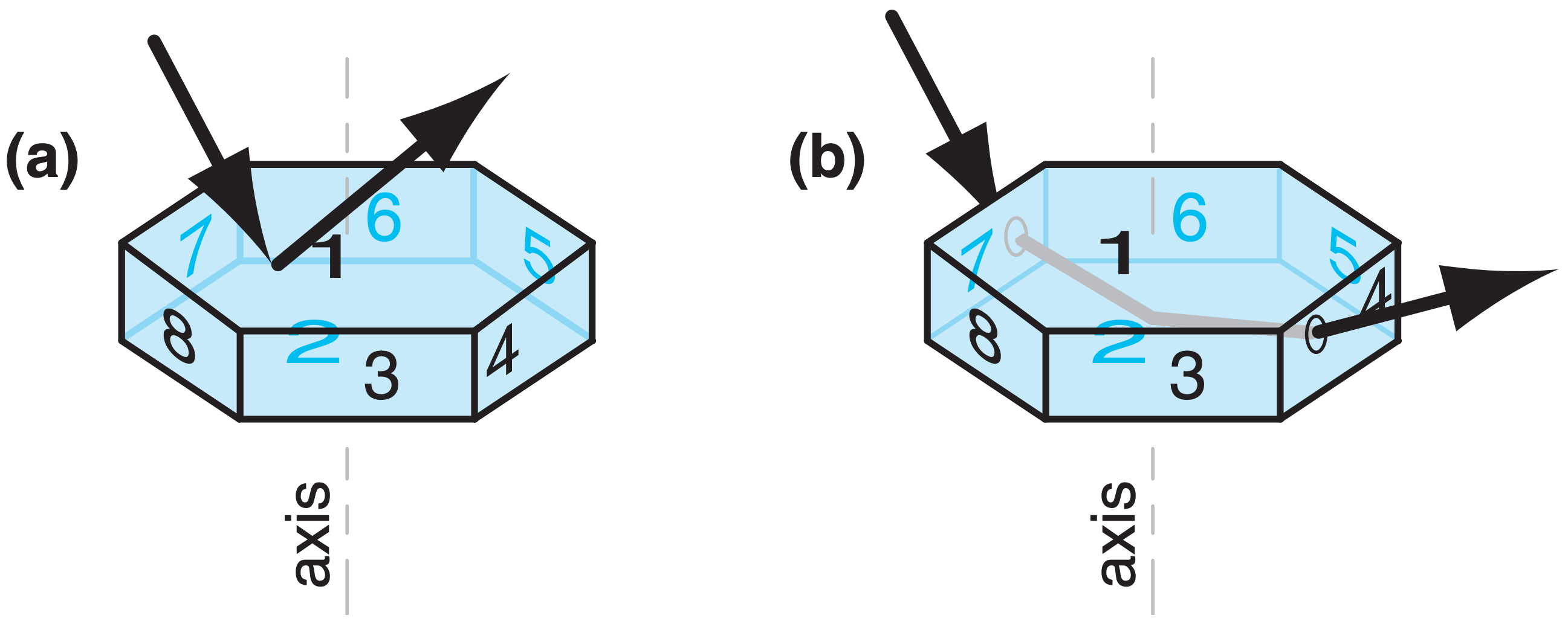
A sun pillar is a vertical column of light that appears to come out of the top (and sometimes the bottom) of the sun (Fig. 22.16). It forms when sunlight reflects off the outside of any of the following nearly-horizontal faces:
- prism faces of large oriented column ice crystals (such as off of face 8 in Fig. 22.18a),
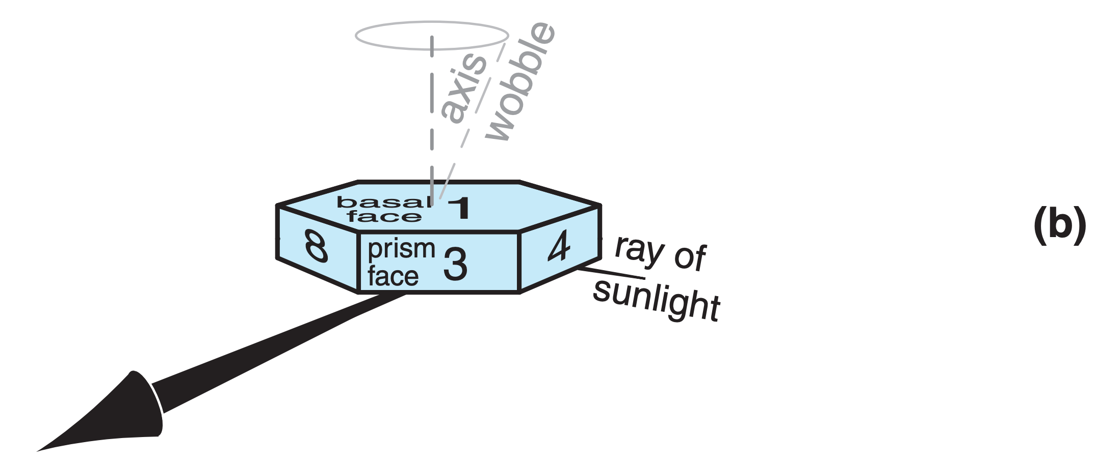
- basal faces of fluttering large oriented plates (such as off face 2 in Fig. 22.18b), or
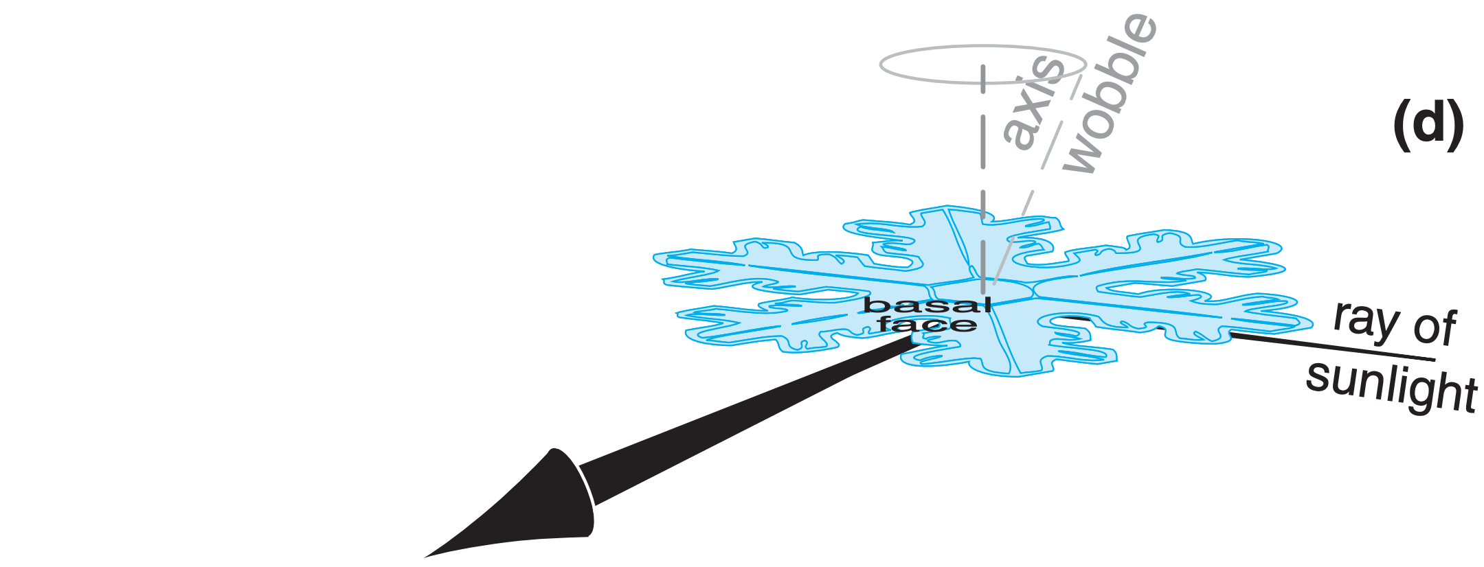
- basal faces of large oriented dendrites (6-armed snowflake plates) (such as off the bottom of the snowflake in Fig. 22.18d).
These crystals act like myriad tiny mirrors.
Internal reflections can contribute to the intensity of sun pillars. In the example of Fig. 22.18c, light enters the ice crystal (with refraction) through face 5, then reflects from the inside of the crystal at face 1, and leaves (with refraction) from face 8.
An end view of this phenomenon for reflection from oriented hexagonal columns is sketched in Fig. 22.19. Column crystals are free to rotate about their column axis as they gently fall to Earth, and flat plates and dendrites have random wobble of their axes causing them to flutter like leaves when they fall. As a result, some of the ice crystals have faces that by chance reflect the sunlight to your eye, while other ice crystals reflect the sunlight elsewhere.
Relatively few sunbeams reflect to your eye, causing the sun pillar to be very faint. The best time to observe sun pillars is at sunrise or sunset when the sun is hidden just below the horizon, but is still able to illuminate the ice precipitation. Sun pillars often appear to be red not because of refraction in the crystal, but because light from the rising or setting sun has lost much of its blue components due to scattering from air molecules before it reaches the ice crystals.
Similar pillars can form above and below:
- bright street lights,
- the moon and bright planets (e.g., Venus), and
- other bright lights, such as aircraft lights.
These pillars often have the same color as the light source.
22.3.2. Parhelic Circle
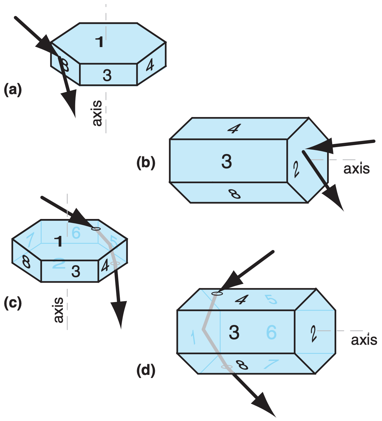
The parhelic circle is a horizontal band of white light extending left and right through the sun (Fig. 22.16). It can be formed by external reflection off of the vertical faces of large hexagonal plates (e.g., face 8 in Fig. 22.20a) or large hexagonal columns (e.g., face 2 in Fig. 22.20b). It can also be formed by internal reflection off of similar vertical faces, such as the ray path touching faces 1-5-2 in Fig. 22.20c, or the path touching faces 4-1-7 in Fig. 22.20d.
These crystals can have any rotation orientation about their axis, causing reflections from many different ice crystals to reach your eye from many different angles left and right from the sun (Fig. 22.21). In other words, they act as a large number of small mirrors.
22.3.3. Subsun
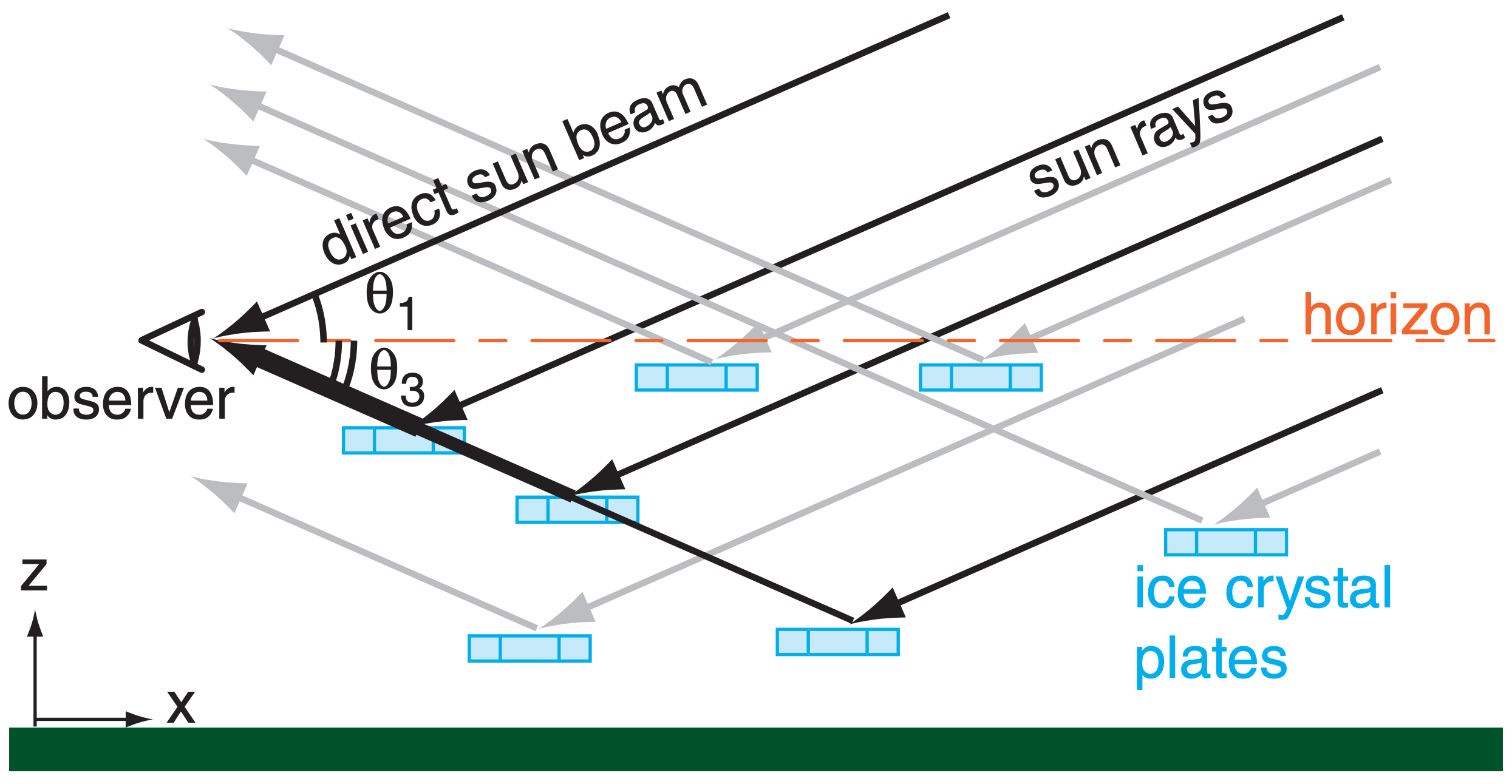
The subsun is a spot of white light seen below the horizon (Fig. 22.16), as viewed looking down from a bridge, mountain, or aircraft. It forms by external reflection of sunlight off of the top surfaces of large hexagonal plates (face 1 in Fig. 22.22a), and by internal reflection (face 2 in Fig. 22.22b; namely, the ray touches faces 7-2-4). If all the hexagonal plates are oriented horizontally, they act as mirrors to produce a simple reflection of the sun (Fig. 22.23). As given by eq. (22.1), the subsun appears the same angle θ3 below the horizon that the sun is above θ1.
22.3.4. 22° Halo
Optics for 22° halos (Fig. 22.16) are not as simple as might be expected. Small ice-crystal columns are free to tumble in all directions. As a result, light rays can enter the crystal at a wide range of angles, and can be refracted over a wide range of sky.
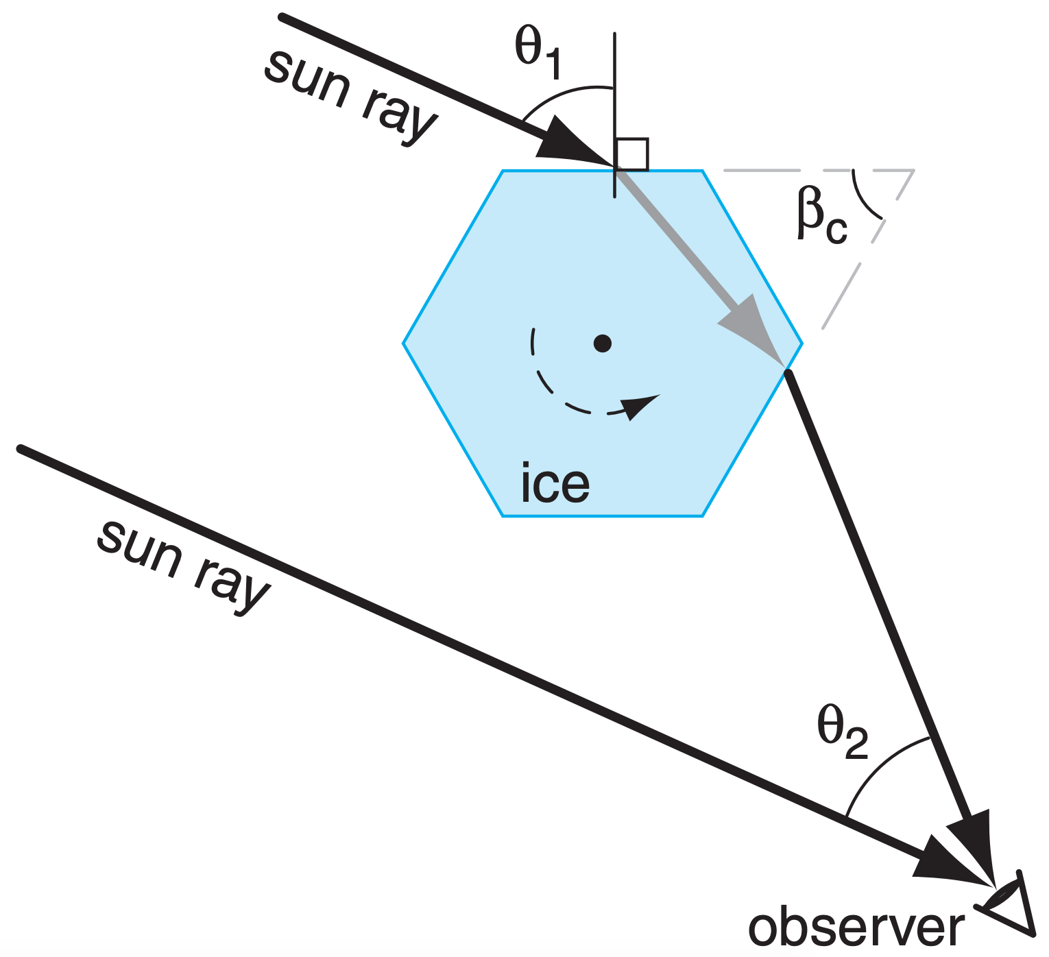
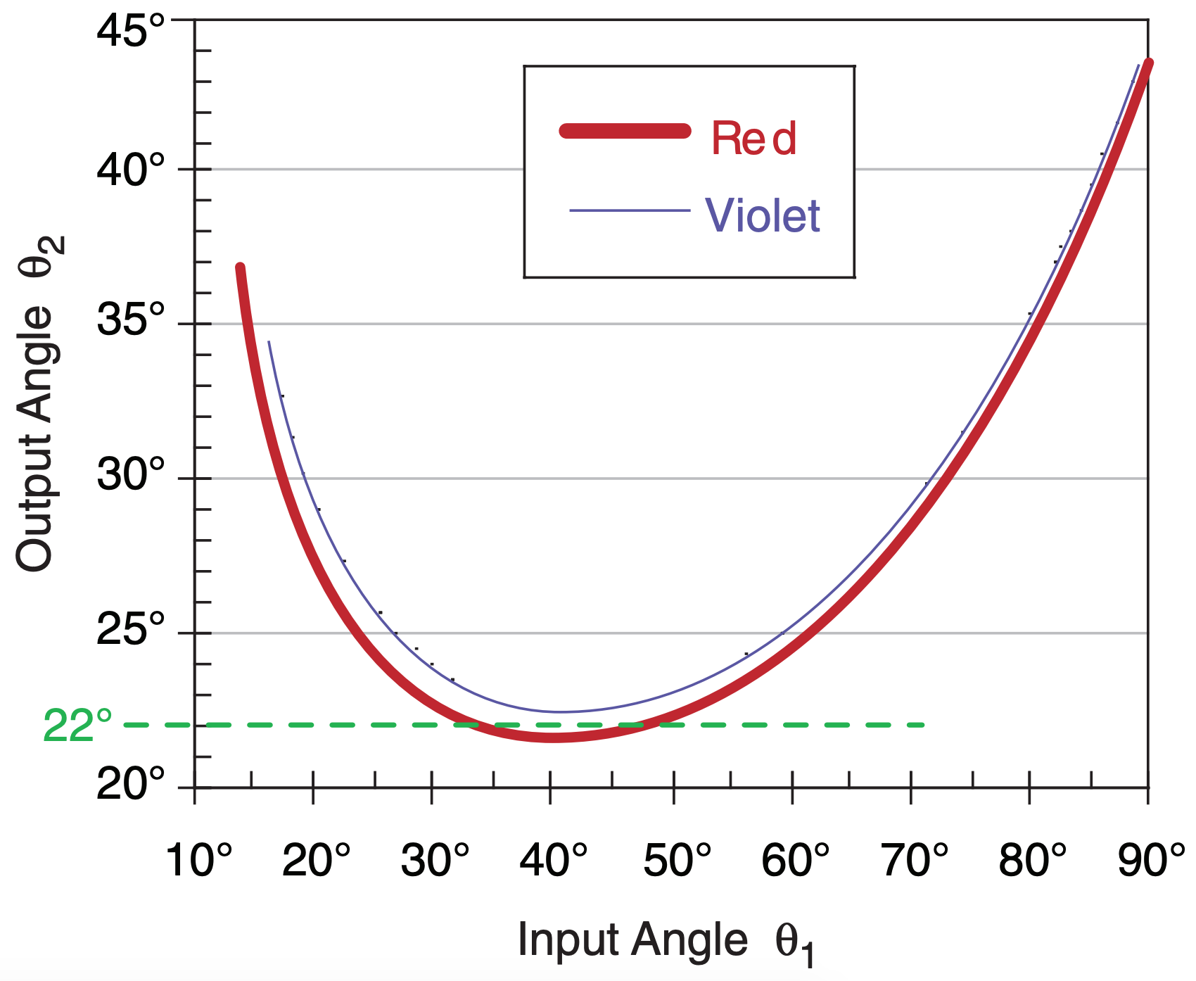
The brightest light that we identify as the halo is caused by refraction through those ice crystals that happen to be oriented with their column axis perpendicular to the sun rays (Fig. 22.24). We will study this special case. Different crystals can nevertheless have different rotation angles about their axis (the dark point in the center of the ice crystal of Fig. 22.24). As a result, the angle of incidence θ1 can vary from crystal to crystal, thereby causing different viewing (output) angle θ2 values.
For hexagonal crystals (for which the wedge angle is βc = 60°) and for the special case of light rays approaching normal to the column axis, Snell’s law yields:
\begin{align}\theta_{2}=\theta_{1}-\beta_{c}+
\arcsin \left\{\frac{n_{i c e}}{n_{a i r}} \cdot \sin \left[\beta_{c}-\arcsin \left(\frac{n_{a i r}}{n_{i c e}} \cdot \sin \theta_{1}\right)\right]\right\}\tag{22.15}\end{align}
where n is refractive index.
Sample Application
What is θ2 if θ1 = 80° and βc = 60° for red light in a 22° halo? T = –20°C, P = 80 kPa, RH = 75%.
Find the Answer
Given: θ1 = 80°. βc = 60°. λ = 0.7 µm for red light.
nair = 1.0002479, nice = 1.3074 from Table 22-1.
Find: θ2 = ?°
Use eq. (22.15) with βc = 60° for hexagonal crystal:
\(\ \theta_{2}=80^{\circ}-60^{\circ}+
\operatorname{asin}\left\{\frac{1.3074 \cdot \sin }{1.0002479}\left[60^{\circ}-\operatorname{asin}\left(\frac{1.0002479}{1.3074} \cdot \sin 80^{\circ}\right)\right]\right\}\)
= 80° – 60° + 14.59° = 34.59°
Check: Units OK. Physics OK.
Exposition: Quite different from 22°, but agrees with Fig. 22.25. Namely, this is one of the light rays that contributes to the bright glow outside the 22° halo, as sketched in Fig. 22.16.
The 22° halo observed by a person is the result of superposition of rays of light from many ice crystals possessing many different rotation angles. Hence, it is not obvious why 22° is a magic number for θ2. Also, if refraction is involved, then why are the red to yellow colors seen most vividly, while the blues and violets are fading to white?
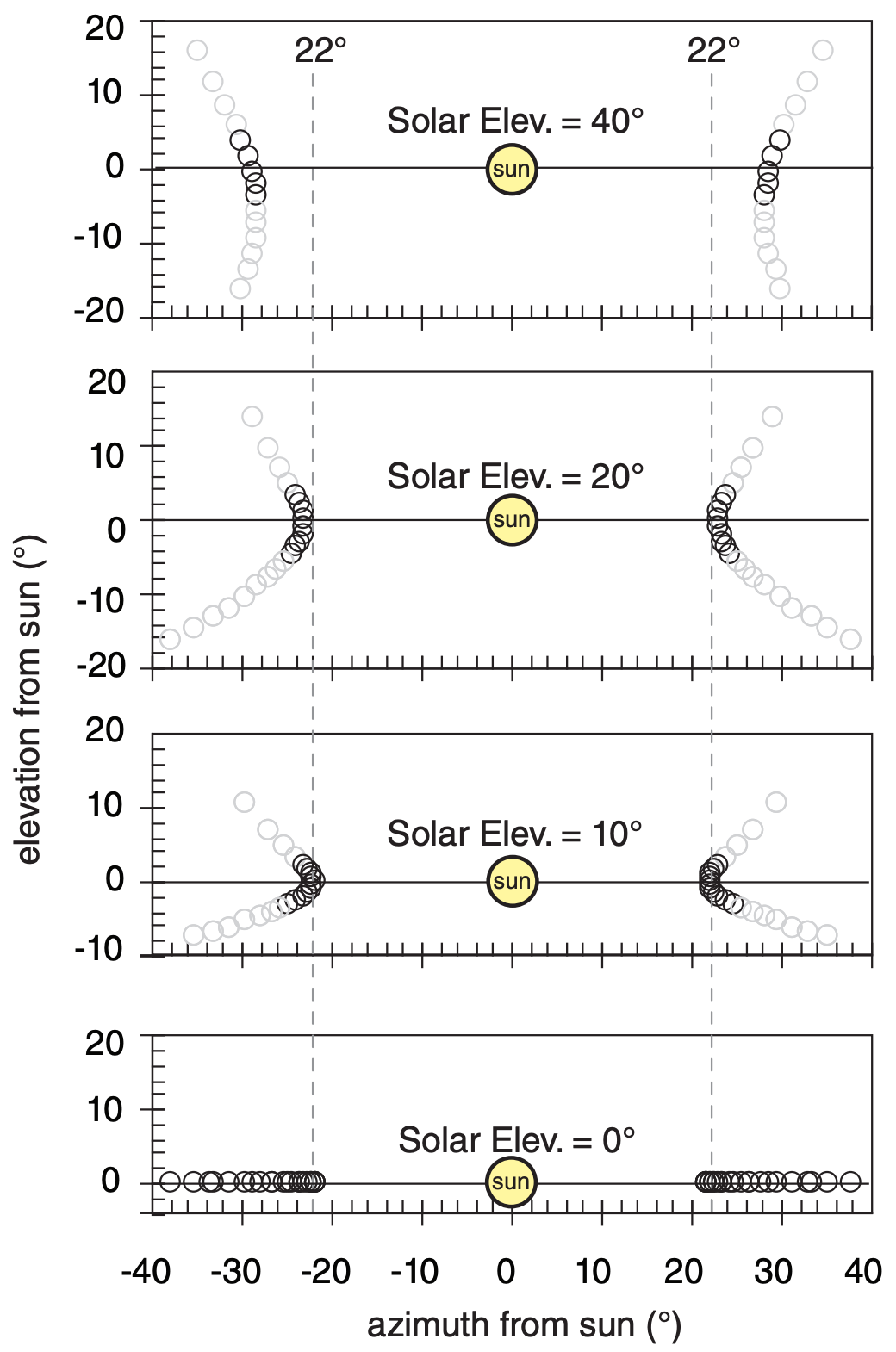
To answer these questions, suppose ice crystals are randomly rotated about their axes. There would be an equal chance of finding an ice crystal having any incidence angle θ1. We can simulate this on a computer spreadsheet by doing calculations for a large number of evenly-spaced incidence angles (for example, every 2° ), and then calculating the set of θ2 angles as an outcome. The result is plotted in Fig. 22.25 for two of the colors (because nair/nice varies with color).
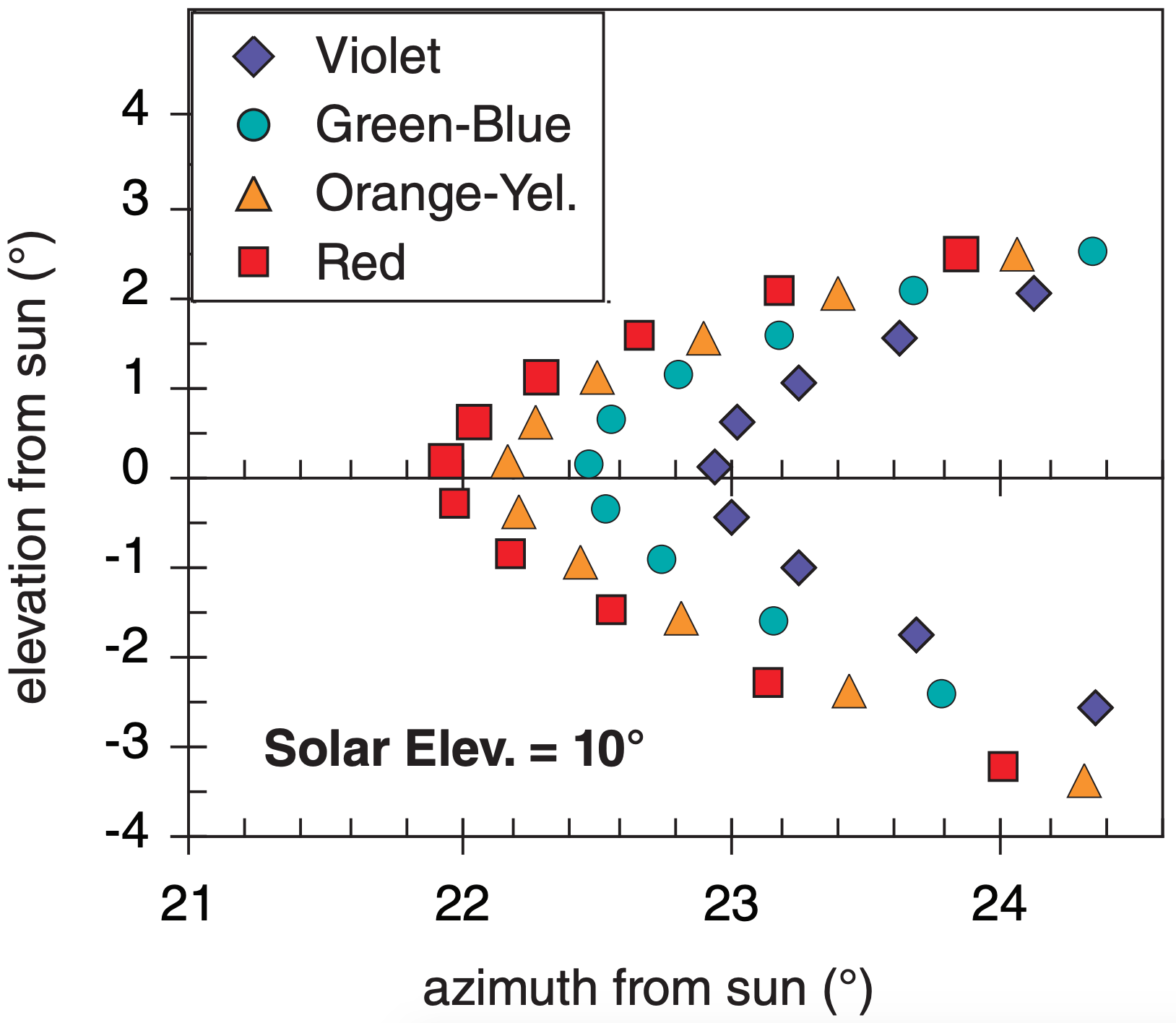
Colors and angles of a 22° halo can be explained using Fig. 22.26 (which is a zoomed view of Fig. 22.25). For viewing (output) angles less than about 21.6°, there is no refracted light of any color; hence, the halo is dark inside (the edge closest to the sun).
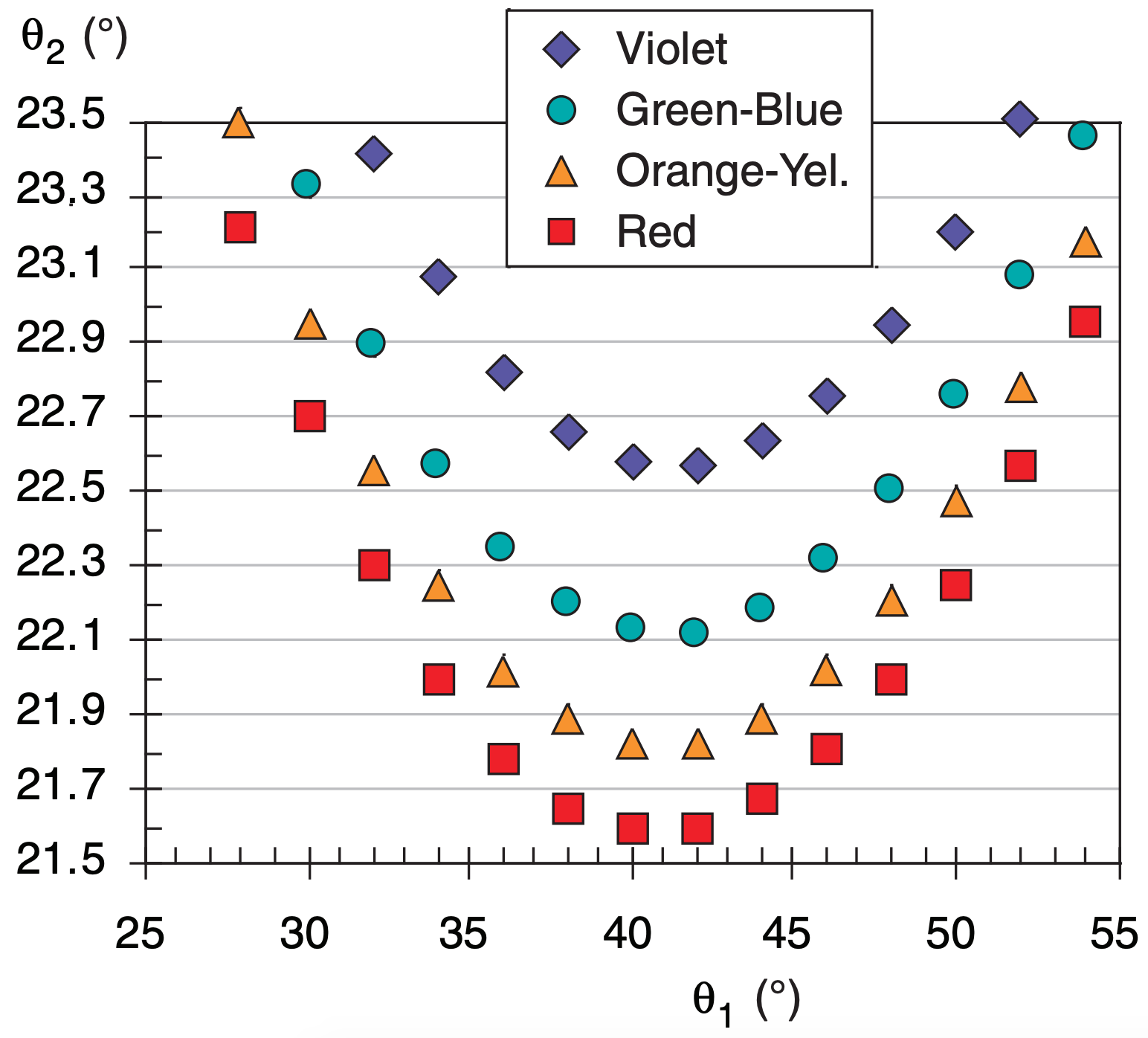
In the range of viewing angles averaging 22° (i.e., from 21.6° to 22.6°), there are 29 data points plotted in Fig. 22.26, which cause the bright ring of light we call the halo. There are also data points at larger angles, but they are more sparse — causing the brightness of the halo to gradually fade at greater viewing angles from the sun.
For a viewing angle range of θ2 = 21.5° to 21.7°, we see four “red light” data points in Fig. 22.26, but no other colors. Thus, the portion of the halo closest to the sun looks bright red. In the next range of viewing angles (21.7° - 21.9°), we see four “yellow-orange” and two “red” data points. Thus, in this range of viewing angles we see bright orange light.
In the angle range 22.1 - 22.3°, there are four bluegreen data points, and two orange-yellows and two reds. These colors combine to make a bluish white color. By an angle of 23° , there are roughly equal portions of all colors, creating white light. Thus, the colors of a 22° halo can have bright reds, oranges, and yellows on the inside, fading to light green and bluish-white further away from the sun.
The minimum viewing angle is the angle for which the halo gets its name, and can be found from:
\begin{align}\theta_{2 \min }=2 \cdot \arcsin \left[\frac{n_{i c e}}{n_{a i r}} \cdot \sin \left(\frac{\beta_{c}}{2}\right)\right]-\beta_{c}\tag{22.16}\end{align}
where βc is wedge angle and n is refractive index. This is at the bottom of the curves in Fig. 22.26.
Sample Application
Find θ2min for green-blue light for wedge angle 60°.
Find the Answer
Given: βc = 60°, nice = 1.3135 for blue-green (λ=0.5 µm).
Find: θ2min = ? ° . (Assume T = –20°C & nair ≈ 1.0 .)
Use eq. (22.16): θ2min = 2·arcsin[1.3135 ·sin(30°)] – 60°
Check: Agrees with Table 22-2.
Exposition: The different colors of the 22° halo are not all at exactly 22°.
CAUTION: If you do these angle calculations on a spreadsheet, don’t forget to convert to/from radians for the sine/arcsine terms.
22.3.5. 46° Halo
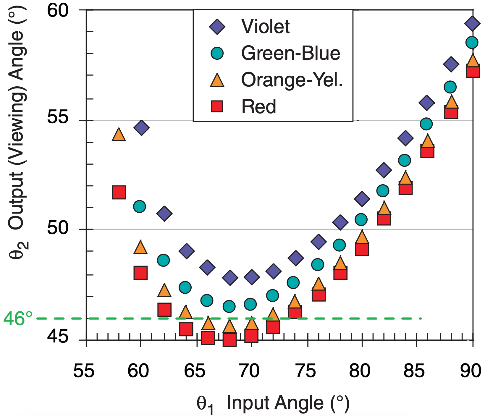
The 46° halo (Fig. 22.16) forms by sun rays shining through a prism face and a basal end of short hexagonal columns (Fig. 22.27). Equations (22.15 and 22.16) apply, but with an ice wedge angle βc = 90°. The resulting viewing angles θ2 are shown in Fig. 22.28 for a variety of input angles θ1. Except for the different radius, this halo has visual characteristics similar to those of the 22° halo. But it is faint, and less frequently seen.
Sample Application
Find the viewing angle θ2 for a 46° halo, given input angle θ1 = 80° and βc = 90° for red light.
Find the Answer
Given: θ1 = 80°, βc = 90°. λ = 0.7 µm for red light.
Find: θ2 = ?°
Assume: nair = 1.0002479, nice = 1.3074 from Table 22-1.
Use eq. (22.15):
\(\ \theta_2 = 80^{\circ} -90^{\circ} + \operatorname{asin}\{\left\{\frac{1.3074 \cdot \sin }{1.0002479}\left[90^{\circ}-\operatorname{asin}\left(\frac{1.0002479}{1.3074} \cdot \sin 80^{\circ}\right)\right]\right\}
=\underline{\bf{49.25^{\circ}}}\)
Check: Units OK. Physics OK.
Exposition: This agrees with Fig. 22.28.
22.3.6. Halos Associated with Pyramid Crystals
Ice crystals with pyramid ends (Fig. 22.17c) have a wide variety of wedge angles depending on the path of the light ray through the crystal. This can cause additional halos of differing radii centered on the sun (Fig. 22.29).
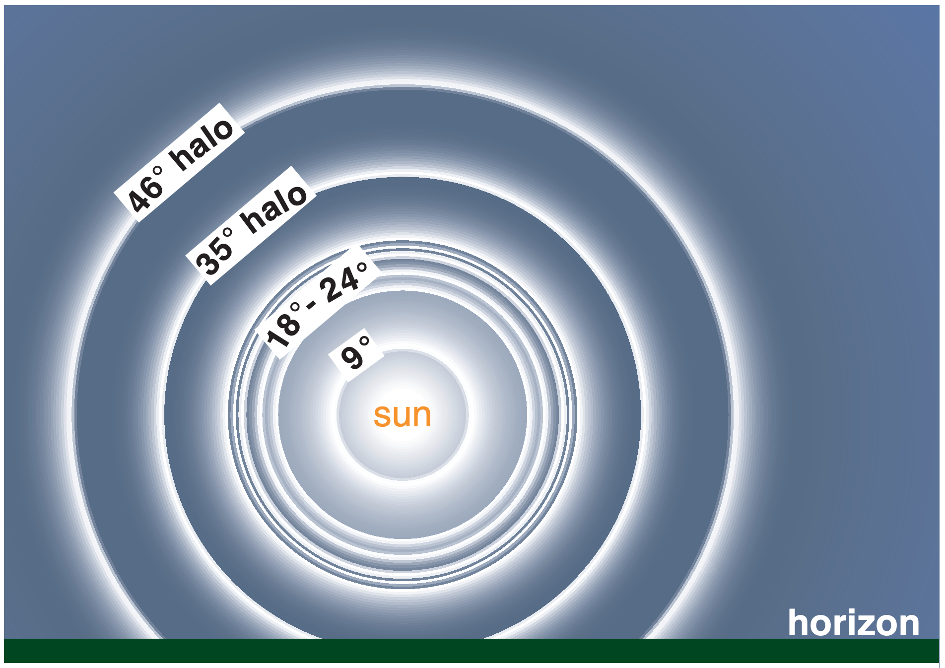
Table 22-2 lists the ray path, wedge angle, and minimum viewing angle (from eq. 22.16) for some of these odd-radius halos. The 9° halo is often hard to see against the glare close to the sun, while the 18°, 20°, 23°, and 24° halos might be mis-reported as 22° halos unless accurate measurements are made. Nonetheless, most of the rare halos have been observed and photographed.
|
Table 22-2. Halo viewing angles (θ2min) found from eq. (22.16). Ray paths refer to the face numbers in the Fig. at right. βc = wedge angle of ice crystal (from W. Tape & J. Moilanen, 2006: “Atm. Halos & the Search for Angle x”. nair ≈ 1.0 |
||||||
| color = | red | yellow orange | green blue | violet | ||
| wavelength (µm) = | 0.7 | 0.6 | 0.5 | 0.4 | ||
| (For T = –20°C) nice = | 1.3074 | 1.3099 | 1.3135 | 1.3199 | ||
| Halo Name | βc (°) | Ray Path | Minimum Halo Viewing Angles (°) | |||
|---|---|---|---|---|---|---|
| 9° | 25 | 18 · 5 | 8.88 | 8.95 | 9.06 | 9.24 |
| 18° | 52.4 | 18 · 24 | 18.11 | 18.27 | 18.49 | 18.89 |
| 20° | 56 | 18 · 15 | 19.73 | 19.90 | 20.14 | 20.58 |
| 22° | 60 | 8 · 4 | 21.64 | 21.83 | 22.10 | 22.59 |
| 23° | 62 | 18 · 7 | 22.65 | 22.85 | 23.14 | 23.66 |
| 24° | 63.8 | 18 · 4 | 23.60 | 23.81 | 24.11 | 24.65 |
| 35° | 80.2 | 18 · 14 | 34.53 | 34.87 | 35.37 | 36.26 |
| 46° | 90 | 1 · 3 | 45.18 | 45.71 | 46.49 | 47.91 |
“The skipper he stood beside the helm,
His pipe was in his mouth,
And he watched how the veering flaw did blow
The smoke now West, now South.
Then up and spake an old Sailor
Had sailed to the Spanish Main,
‘I pray thee, put into yonder port,
For I fear a Hurricane.
Last night the moon had a golden ring,
And tonight no moon we see!’
The skipper he blew a whiff from his pipe,
And a scornful laugh laughed he.”
– by Henry Wadsworth Longfellow, from
The Wreck of the Hesperus.
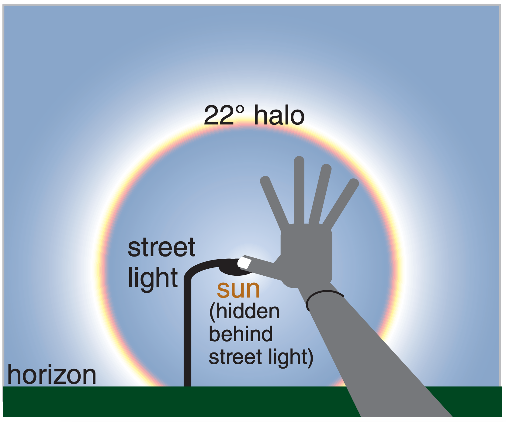
For most people, if you extend your arm fully and open your hand as widely as possible, then the angle that you see subtended by your hand is about 22°. This works for people of different sizes, because hand size and arm length are often proportional.
To view halos, first move so that the sun is hidden behind an obstacle such as a street light, stop sign, or a corner of a building, so you don’t blind yourself. Then extend your arm and stretch your hand, and position the tip of your thumb over the location where the center of the sun would be (hidden behind the obstacle). The tip of your little finger should just touch the halo if it is indeed a 22° halo.
22.3.7. Circumzenithal & Circumhorizonal Arcs
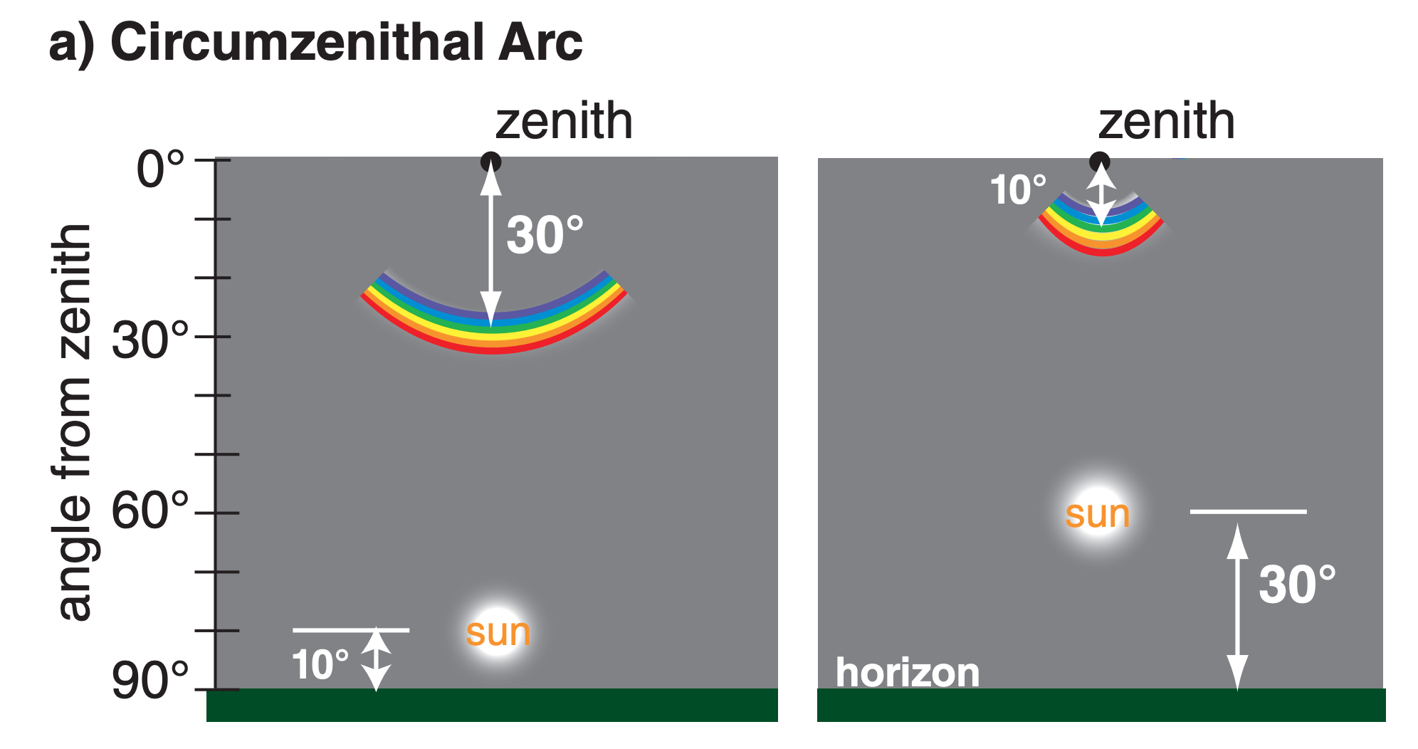
Circumzenithal arcs and circumhorizonal arcs are similar (Fig. 22.30). They are both portions of circles at constant viewing angle above the horizon, and thus at constant viewing angle from the zenith (the point directly above the viewer). They are lines parallel to the horizon that partially encircle the viewer. Only the portion of the circle within about ±45° azimuth of the sun’s azimuth from the viewer are visible; hence, they are seen as arcs, not circles.
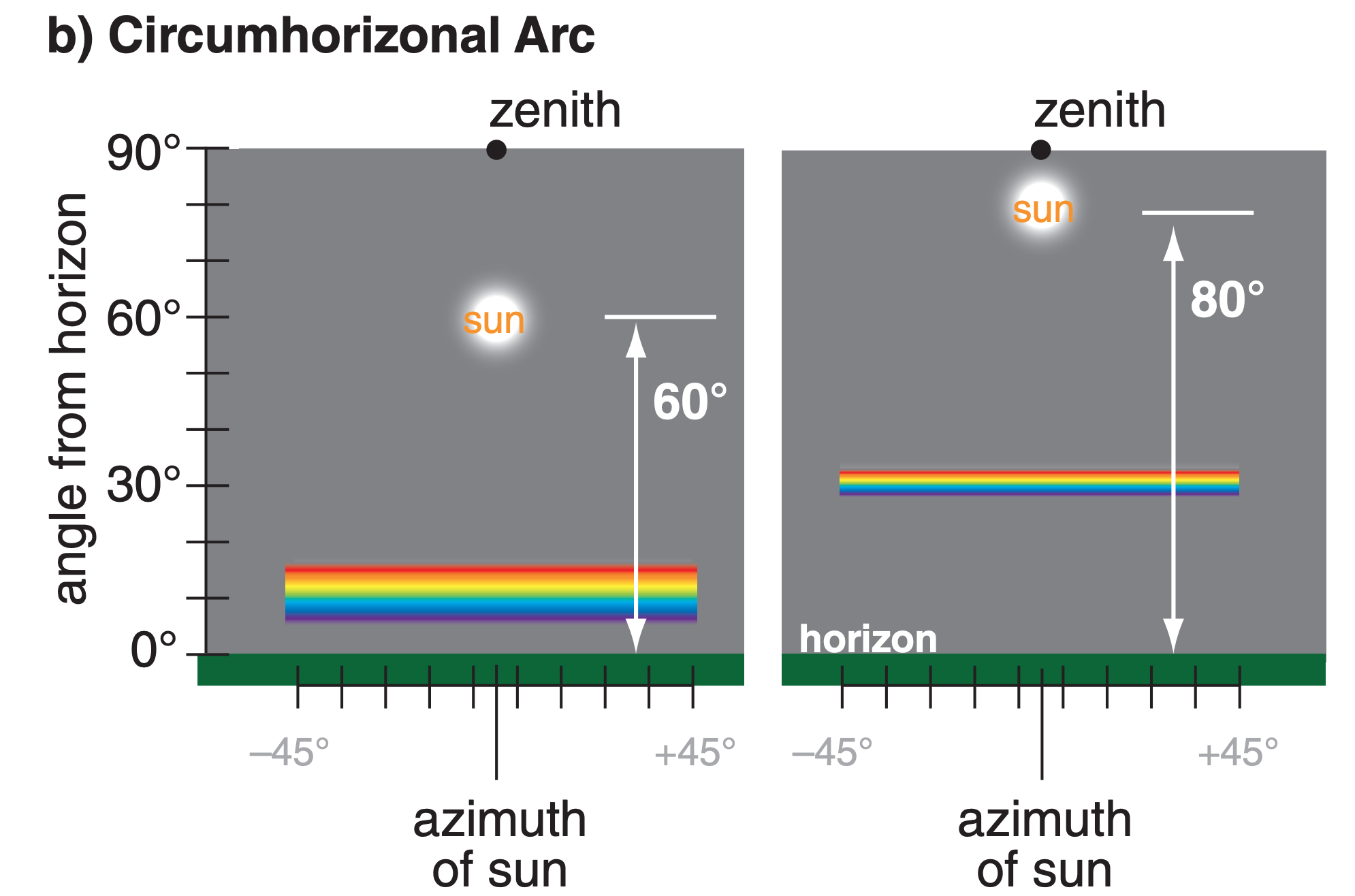
Both arcs are caused by light refracted through the βc = 90° wedge angle of large oriented hexagonal plates (Fig. 22.31). For circumzenithal arcs the light ray enters the top of the plate (through basal face 1) and exits through the side (such as through prism face 8 in Fig. 22.17b). For circumhorizonal arcs the ray enters a side (such as face 5) and exits the bottom (face 2). Because refraction is involved, these arcs can be colorful, with red closest to the sun.
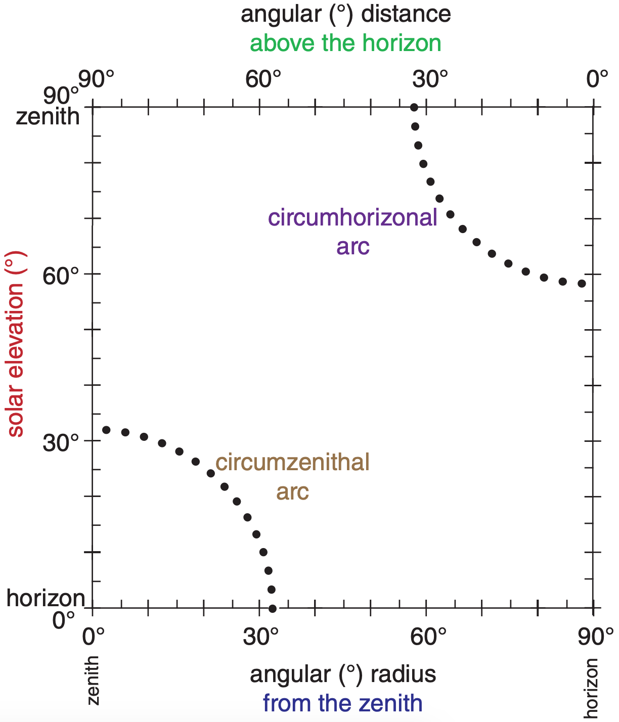
The arc’s viewing angle from the zenith (i.e., the apparent radius of the arc) varies with solar elevation (Fig. 22.32). The circumzenithal arc is seen high in the sky (above the sun) only when the sun is low in the sky (for solar elevation angles of 0° < Ψ < 32°). The circumzenithal arc is always outside the 46° halo (Fig. 22.16).
The circumhorizonal arc is seen low in the sky (below the sun) only when the sun is high in the sky (58° < Ψ ≤ 90°). At high latitudes the circumhorizonal arc is never visible because the sun never gets high enough in the sky.
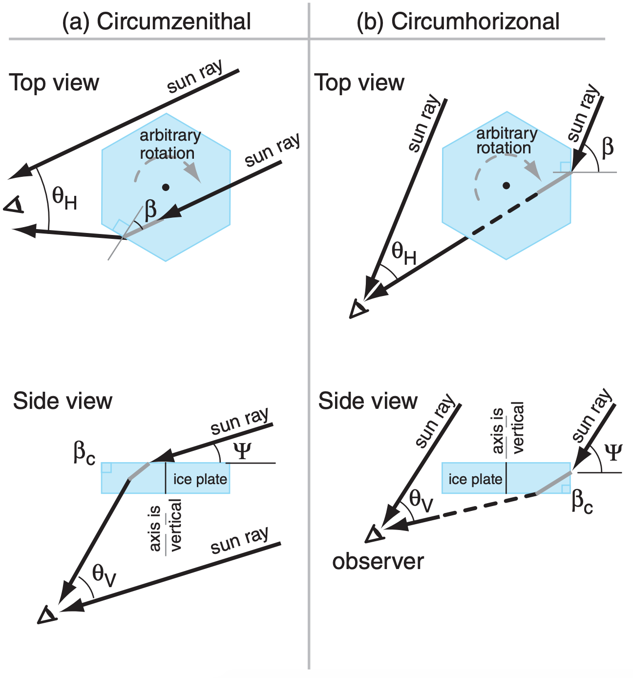
To illustrate how these arcs form, we will focus on just one of them — the circumzenithal arc. The large hexagonal plates can assume any rotation angle β about their vertically-oriented column axis. At different times and locations, there are different solar elevation angles ψ. The ray equations for vertical viewing angle θV (elevation above the sun) and horizontal angle θH (azimuth from the sun) are:
\begin{align}\begin{aligned}
&\theta_{V}=S_{\alpha}\left[\arccos \left(\mu_{a i} \cdot \cos \psi\right), \beta, \mu_{i a}\right]-\psi\\
&\theta_{H}=S_{\beta}\left[\arccos \left(\mu_{a i} \cdot \cos \psi\right), \beta, \mu_{i a}\right]-\beta
\end{aligned}\tag{22.17}\end{align}
Subscripts “ai” are for rays going from air to ice (e.g., μai = nair/nice), while subscripts “ia” are from ice to air (e.g., μia = nice/nair).
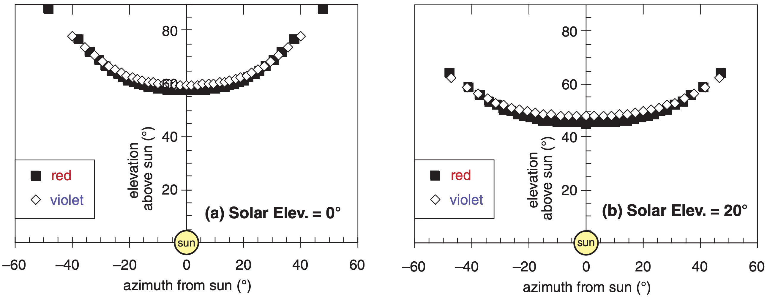
A spreadsheet can be used with a large number of evenly spaced values of β to simulate the superposition of rays from a large number of randomly-rotated ice plates. The resulting locus of output viewing angles traces the circumzenithal arc in Fig. 22.33.
Eq. (22.17) does not account for some ray paths that might reflect from the outside of the crystal instead of entering, nor does it include the critical angle for rays already inside the crystal. Thus, some of the points plotted in Fig. 22.33 might not be possible, because the sun rays corresponding to those points either cannot enter the crystal, or cannot leave it.
“It is clear and cold... And all about is snow and silence. And in the sky are three suns, and all the air is flashing with the dust of diamonds.”
– Jack London, on a trip down the Yukon River in search of gold in Alaska.
Sample Application
For a circumzenithal arc, what are the elevation and azimuth viewing angles (relative to the sun)? Solar elevation is 10°. Rotation angle is β = 20°. Assume nearly red light with: nair = 1.0002753 and nice = 1.307 .
Find the Answer
Given: Ψ = 10°, β = 20°, nair = 1.0002753, nice = 1.307
Find: θV = ?°, and θH = ?°
First, find the refraction parameters:
μai = nair/nice = 0.7653, and μia = 1/μai = 1.3067
Next: arccos[μaicos(Ψ)] = arccos(0.7653·cos10°) = 41.09°
Then, use eqs. (22.17):
θV = Sα[41.09° , 20° , 1.3067] – 10°
θH = Sβ[41.09° , 20° , 1.3067] – 20° .
To find the S values, we first need to use eq. (22.8):
\(\ b_{\alpha \beta} =\frac{(1.3067)^{2}}{1+\left[1-(1.3067)^{2}\right] \cdot\left\{\left[\tan \left(41.09^{\circ}\right)\right]^{2}+\left[\tan \left(20^{\circ}\right)\right]^{2}\right\}} =4.634\)
Then use eq. (22.9):
\(\ S_{\alpha}\left(\alpha_{1}, \beta_{1,}, \mu_{12}\right)=\arctan \left[\left\{4.634 \cdot[\tan (41.09)]^{2}\right\}^{1 / 2}\right]\)
Sα = 61.95°
Similarly: Sβ = 38.08°
Finally: θV = 61.95° – 10° = 51.95°
θH = 38.08° – 20° = 18.08°
Check: Units OK. Physics OK.
Exposition: This answer agrees with Fig. 22.33b. Obviously this calculation is tedious for more than one ray, but it is easy on a spreadsheet.
22.3.8. Sun Dogs (Parhelia)
Parhelia are bright spots of light to the right and left of the sun, roughly 22° from the sun (Fig. 22.16). As the sun moves through the sky, the parhelia move with the sun as faithful companions — earning their nickname sun dogs.
They are formed when light shines through the sides (prism faces) of large horizontal ice-crystal plates that gently fall through the air with their column axes vertical. The crystals are free to rotate about their column axes, so there is no favored rotation angle.
Because of the preferred orientation of the column axis, sun-dog optics depend on the solar elevation angle. When the sun is on the horizon, sun rays shine through the crystal as sketched in Fig. 22.34a, with a nearly horizontal path through prism faces such as 8-4. This causes the parhelia at a viewing angle of 22° from the sun. If a 22° halo is also present due to other smaller ice crystals in the air, then each parhelion appears as a bright spot on the halo to the right or left of the sun.
For higher sun angles (Fig. 22.34b), ice-crystal geometry causes the sun dogs to move horizontally further away from the sun. For example, at a solar elevation angle of Ψ = 47°, the sun dogs are at a horizontal viewing angle of 31° from the sun; namely, they are found outside the 22° halo. As the solar elevation angle becomes greater than about 60°, the sun dog is so faint and so far from the 22° halo that it effectively ceases to exist.
For a single ray input from the sun, let β be the rotation angle of the ice-crystal plate about its column axis. The ray equation for a sun dog is:
\begin{align}
\begin{aligned}
\theta_{V}=& S_{\alpha}\left[S_{\alpha}\left(\psi, \beta, \mu_{a i}\right), 60^{\circ}-S_{\beta}\left(\psi, \beta, \mu_{a i}\right), \mu_{i a}\right]-\psi \\
\theta_{H}=& S_{\beta}\left[S_{\alpha}\left(\psi, \beta, \mu_{a i}\right), 60^{\circ}-S_{\beta}\left(\Psi, \beta, \mu_{a i}\right), \mu_{i a}\right] +\beta-60^{\circ}
\end{aligned}\tag{22.18}\end{align}
where θV is the viewing angle of the output ray (elevation above the sun), and θH is the viewing angle (azimuth to the right of the sun).
The sun dog as viewed by an observer is the superposition of rays from many ice crystals having a variety of rotation angles. For randomly rotated crystals, there is an equal chance of any β between 0° and 90°. This is simulated on a spreadsheet by solving the sun-dog equation for a large number of equally-spaced β angles. The results are plotted in Fig. 22.35. For a finite-sized ice crystal with aspect ratio typical of hexagonal plates, ray paths with large vertical viewing angle are not physically possible because the light ray would exit or reflect from a basal face before reaching the required prism face.
Sun dog colors are similar to the halo, with bright red on the inside (closest to the sun), then orange and yellow, but with green, blue, and violet fading to white (Fig. 22.36 is an expanded view of Fig. 22.35.)
Sample Application
Find the vertical and horizontal viewing angles of a sun-dog ray of red light for solar elevation 40° and crystal rotation β = 45°.
Find the Answer
Given: Ψ = 40°, β = 45°
Assume for red light: nair ≈ 1.0002753, nice ≈ 1.307
Find: θV = ?°, θH = ?°
Use eq. (22.18), with µai = 0.7653 from before:
\(\ \theta_{V}=S_{\alpha}\left[S_{\alpha}\left(40^{\circ}, 45^{\circ}, 0.7653\right),\right.
60^{\circ}-S_{\beta}\left(40^{\circ}, 45^{\circ}, 0.7653\right), 1.3067]-40^{\circ}\)
\(\ \theta_{H}=S_{\beta}\left[S_{\alpha}\left(40^{\circ}, 45^{\circ}, 0.7653\right),\right.
\left.\left\{60^{\circ}-S_{\beta}\left(40^{\circ}, 45^{\circ}, 0.7653\right)\right\}, 1.3067\right]+45^{\circ}-60^{\circ}\)
For the Sα and Sβ inside the square brackets:
bαβ = 0.3433, Sα = 26.18° , Sβ= 30.37°
For outside the square brackets: bαβ = 2.8448, because
Sα[26.18°, (60°–30.37°), 1.3067] = Sα[26.18°, 29.63°, 1.3067] = 39.67°
Sβ[26.18°, 29.63°, 1.3067] = 43.81°
Finally:
θV = 39.67° – 40° = –0.332°
θH = 43.81° – 15° = 28.81°
Check: Units OK. Physics OK.
Exposition: This portion of the sun dog is nearly at the same elevation as the sun, but is 28.81° to the side of the sun. This is 6.81° outside of the 22° halo.
22.3.9. Subsun Dogs (Subparhelia)
Subparhelia (spots of light to the left and right of the subsun) are sketched in Fig. 22.16. Ray geometry for a subsun dog is identical to that for a sun dog, except that the ray within the ice reflects from the inside of the bottom (basal) face (face 2 in Fig. 22.34c), in addition to refractions through prism faces when entering and exiting the crystal.
22.3.10. Tangent Arcs
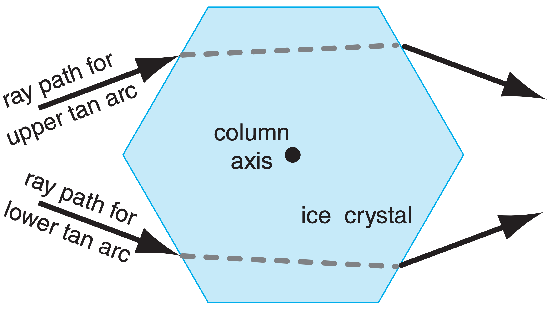
Tangent arcs are caused when light rays are refracted through large hexagonal column ice crystals, which often fall with their column axis nearly horizontal (Fig. 22.17a). Three phenomena in this tangent-arc category include the upper tangent arc, the lower tangent arc, and the circumscribed halo. We will examine the optics of upper tangent arcs in detail, and then briefly discuss the others.
22.3.10.1. Upper tangent Arc
In Fig. 22.16, the upper tangent arc is just above (and is tangent to) the 22° halo. The shape of this arc changes with solar elevation angle, Ψ.
In the absence of wind shear, the ice-crystal column axes can point in any compass direction within the horizontal plane. Thus, the crystal axis can have any directional orientation γ with respect to the compass direction of the incoming sun ray. The crystal can also have any rotation angle α1 about the column axis (see Fig. 22.37).
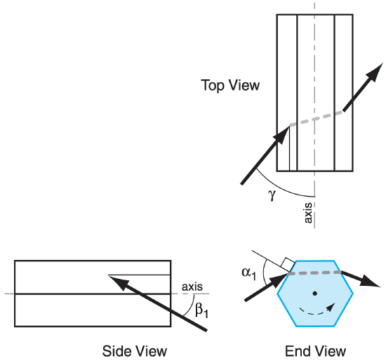
Because there are three input angles for this case, the solution of ray paths is quite nasty. The equations below show how one can calculate the ray output vertical viewing angle θV (elevation above the sun), and the horizontal viewing angle θH (azimuth from the sun), for any input ray. All other variables below show intermediate steps.
As before, one must examine rays entering many crystals having many angles in order to generate the locus of points that is the upper tangent arc. Even on a spreadsheet, this solution is tedious. For simplicity, no consideration was made for the finite size of the crystal, or for rays that cannot enter the crystal due to reflection, or for rays that are trapped inside because of critical-angle effects.
Given: Ψ, α1, and γ :
\begin{align}\begin{aligned}
&\beta_{1}=\arctan \left[\cos (\gamma) \cdot \tan \left(90^{\circ}-\Psi\right)\right]\\
&\alpha_{3}=60^{\circ}-S_{\alpha}\left(\alpha_{1}, \beta_{1}, \mu_{a i}\right)\\
&\beta_{3}=S_{\beta}\left(\alpha_{1}, \beta_{1}, \mu_{a i}\right)\\
&\alpha_{5}=60^{\circ}-S_{\alpha}\left(\alpha_{3}, \beta_{3}, \mu_{i a}\right)-\alpha_{1}
+\arctan \left[\sin (\gamma) \cdot \tan \left(90^{\circ}-\psi\right)\right]\\
&\beta_{5}=S_{\beta}\left(\alpha_{3}, \beta_{3}, \mu_{i a}\right)\\
&G=\left[\tan \left(\alpha_{5}\right)\right]^{2}+\left[\tan \left(\beta_{5}\right)\right]^{2}\\
&\varepsilon=\arctan \left[\frac{\tan \left(\beta_{5}\right)}{\tan \left(\alpha_{5}\right)}\right]\\
&\phi=90^{\circ}-\gamma-\varepsilon\\
&\theta_{V}=90^{\circ}-\psi-\arctan \left[G^{1 / 2} \cdot \cos (\phi)\right]\\
&\theta_{H}=\arctan \left[\sin (\phi) \cdot\left(\frac{G}{1+G \cdot[\cos (\phi)]^{2}}\right)^{1 / 2}\right]
\end{aligned}\tag{22.19}\end{align}
To keep the spreadsheet calculations to a finite size, we used γ in the range of 55° to 90°, and α1 in the range of 0° to 90°. The results for two solar elevations are shown in Fig. 22.38.
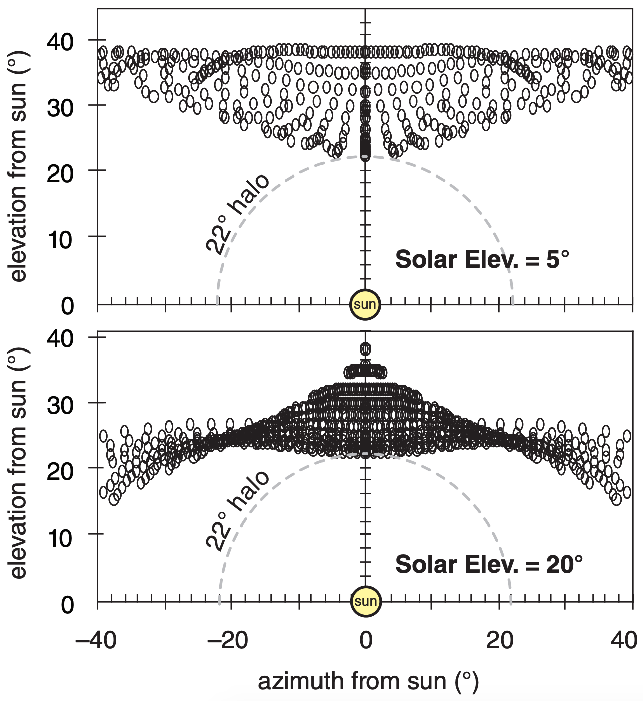
The locus of points of the upper tangent arc looks like the wings of a bird. For low solar elevations, the wings are up in the air. As the sun rises in the sky, the wings gently lower. At solar elevations of about 45° or more the wings are wrapped closely around the 22° halo. Above about 60° solar elevation, there is no solution to the upper tangent arc that is physically realistic.
Sample Application
Find the vertical and horizontal viewing angles of a ray of red light in an upper tangent arc for solar elevation Ψ = 10°, crystal rotation α1 = 76°, and crystal axis direction γ = 45°.
Find the Answer
Given: Ψ = 10°, α1 = 76°, γ = 45°.
Assume: nair ≈ 1.0002753, nice ≈ 1.307
Find: θV = ?°, θH = ?°
Use eqs. (22.19). Various intermediate results are:
β1 = 76°
bαβ = 0.0402 (1st calculation)
α3 = 21.2°, β3 = 38.8°
bαβ = 3.9142 (2nd calculation)
α5 = 22.50°, β5 = 57.84°
G = 2.701, ε = 75.4°, ϕ = –30.4°
Check: Units OK. Physics OK.
Exposition: This one data point within the upper tangent arc is above the sun and above the top of the 22° halo, but is off to the right. These calculations would need to be repeated for many other values of input angles to create an image similar to Fig. 22.38
22.3.10.2. Lower Tangent Arcs
Figs. 22.39 show lower tangent arcs, which occur during the same conditions as upper tangent arcs. Lower tangent arcs are tangent to the bottom of the 22° halo. Upper and lower tangent arcs have similar ray paths (Fig. 22.40) through large hexagonal column ice crystals. Eqs. (22.19) also apply to lower tangent arcs.
For solar elevations of 22° or less, you cannot see the lower tangent arc unless you look down into icecrystal filled air. You can have such a view from aircraft, mountain peaks, bridges or tall buildings.
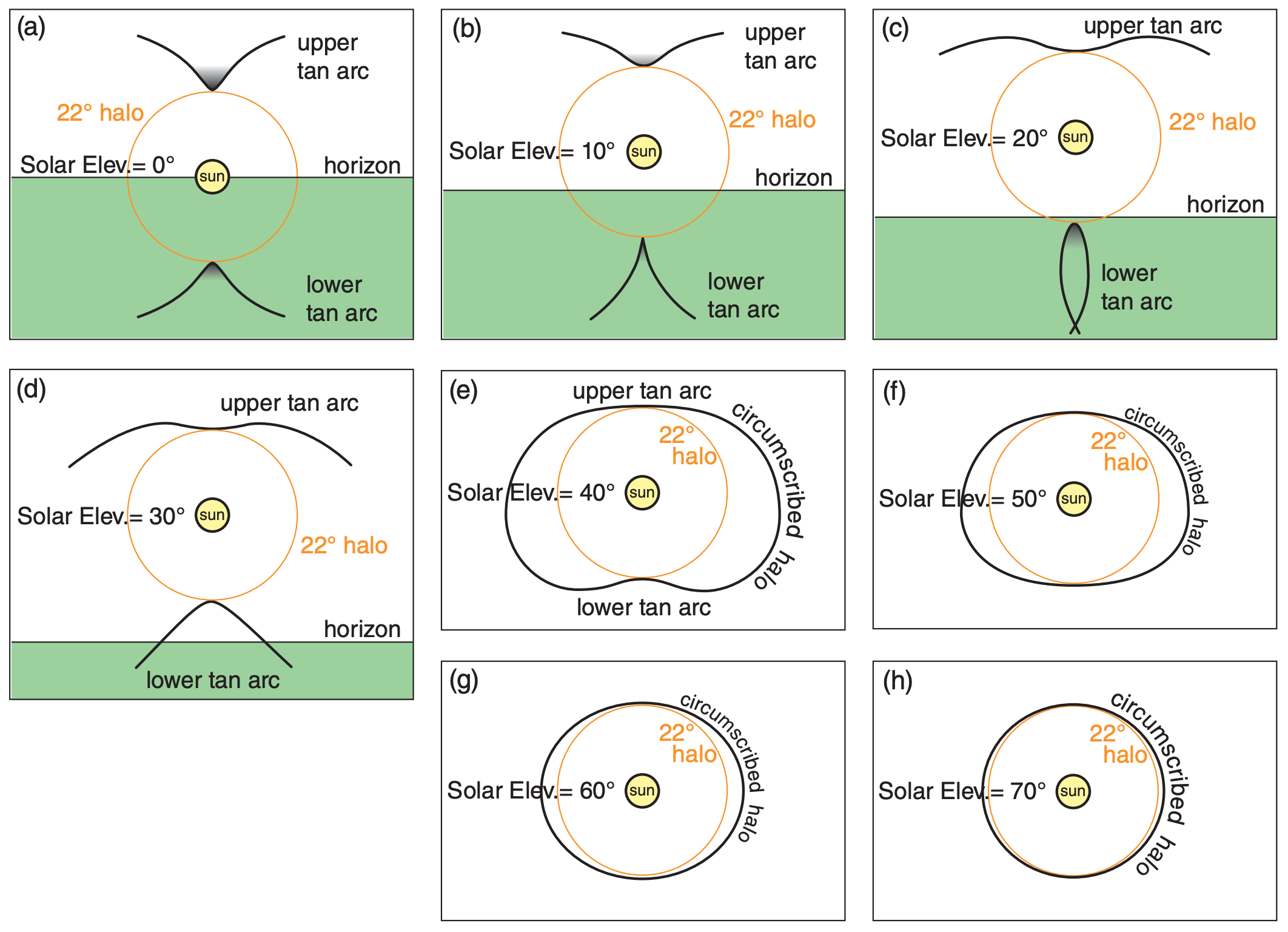
22.3.10.3. Circumscribed Halo
At solar elevations of 29° and greater, the upper and lower tangent arcs merge to form a circumscribed halo (Figs. 22.39). At solar elevations above 70°, the circumscribed halo is so tight around the 22° halo that they are often indistinguishable.
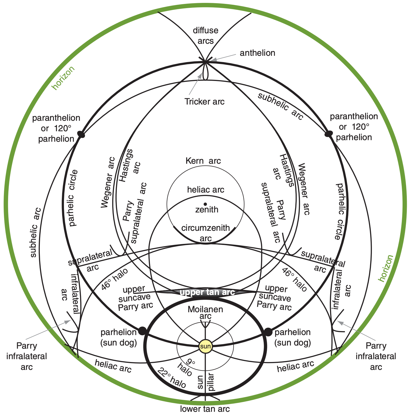
22.3.11. Other Halos
Fig. 22.41 and Table 22-3 show most of the halos and arcs.
| Table 22-3. Alphabetical catalog of halos. Fig. 22.41 shows most of these halos. | |
|
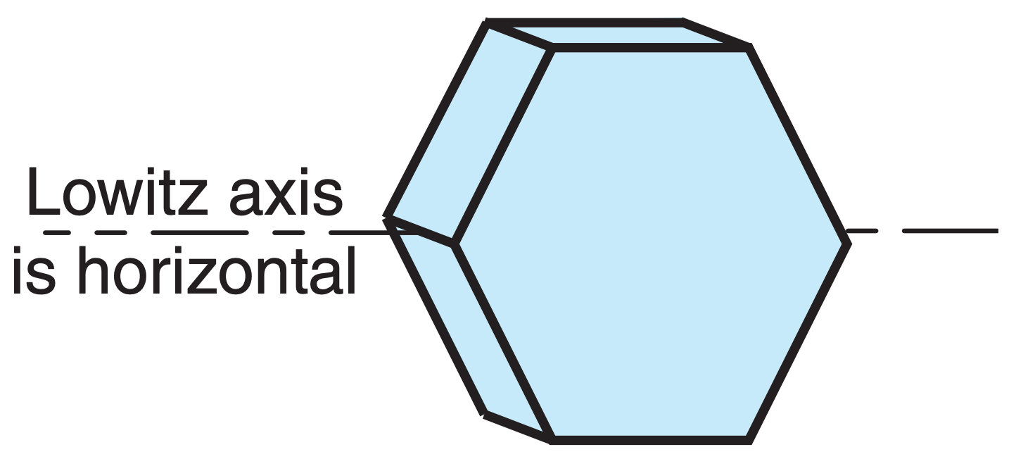
Legend: Ice crystals: A = large oriented hexagonal pyramid a = small hex. pyramid (random orientations) C = large hexagonal column (col. axis horiz.) c = small hex. column (random orientations) L = Lowitz large hex. plate (see INFO Box) P = large hexagonal plate (col. axis vertical) |
Angles: 22° ≈ angle of phenomenon from sun, associated with 60° ice wedge angle 46° ≈ angle of phenomenon from sun, associated with 90° ice wedge angle Optics: m = (mirror) = one or more reflections r = one or more refractions |
|
9° halo, a, r 9° Parry arc, A, r 18° halo, a, r 20° halo, a, r 22° halo, c, r 22° Lowitz arcs (upper & lower), L, r (rare 22° Parry arcs (upper & lower; suncave & sunvex), C, r 23° halo, a, r 24° halo, a, r 35° halo, a, r 44° parhelia (sun dogs of sun dogs, formed when light passes through 2 hex. plates), 2P, 22°, r 46° halo, c, r 46° Lowitz arcs, L, r (extremely rare) 46° Parry arcs (infralateral, supralateral), C, r 120° parhelia (left & right), P, r, m Anthelic arc, C, r, m (= Antisolar arc) Anthelion (a crossing point of diffuse & anthelic arcs) Antisolar arc, C, r, m (= Anthelic arc) Circumhorizonal arc, P, 46°, r (also Parry) Circumscribed halo, C, 22°, r Circumzenithal arc, P, 46°, r (also Parry) Diffuse arcs, C, r, m Halos (see 9° through 46° halos above) Hastings arcs (of upper suncave Perry arc; and of lower suncave Perry arc), r, m Heliac arc, C, m or (r, m) Infralateral arc, C, 46°, r (also Parry) Kern arc, P, 46°, r, m (rare) Lower suncave Parry arc, C, 22°, r Lower sunvex Parry arc, C, 22°, r Lower tangent arc, C, 22°, r Lower Wegener arc, C, r, m |
Lowitz arcs (upper & lower), L, 22°, r (rare) Moilanen arc (rare; seen in ice crystals from snow-making machines) Paranthelia (= 120° parhelia, left & right), P, r, m Parhelia (sun dogs) (left & right), P, 22°, r Parhelic circle, [P, m or (r, m)] or [C, m or (r, m)] (also Parry) Parry arcs (Many arcs. See separate listings for: 9°, upper suncave, upper sunvex, lower suncave, lower sunvex, circumzenithal, circumhorizonal, infralateral, supralateral, Hastings, helic, subhelic, anthelic, subanthelic) (see Fig. 22.41) Scheiner’s 28° halo (from cubic Ic ice crystals), r Subanthelic arc, C, r, m Subcircumzenith arc, P, 46°, r, m (not yet observed) Subhelic arc, C, r, m Subhorizon halo (halos and arcs below the horizon, including portions of diffuse, Tricker, subhelic, lower Wegener, and lower tangent arcs) Subparhelia (subsun dogs) (left & right), P, 22°, r, m Subparhelic circle, [P, r, m] or [C, r, m] Subsun, P, r Subsun dogs (subparhelia) (left & right), P, 22°, r, m Sun dogs (parhelia) (left & right), P, 22°, r Sun pillar, C or P, r Supralateral arc, C, 46°, r (also Parry) Tangent arc (upper & lower), C, 22°, r Tricker arc, C, r, m Upper suncave Parry arc, C, 22°, r Upper sunvex Parry arc, C, 22°, r Upper tangent arc, C, 22°, r Upper Wegener arc, C, r, m Wegener arcs (upper & lower), C, r, m |
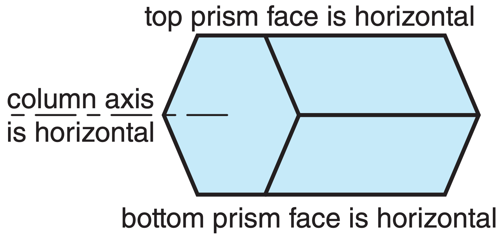
A Parry-oriented column crystal has both a horizontal column axis and horizontal top and bottom prism faces (see Fig. at right). Resulting Parry arcs (Fig. 22.41) are observed 1% as frequently as 22° halos.
In year 1629, Christopher Scheiner observed a rare 28° halo. It has been observed only about 6 times since then. One explanation is that sun rays pass through an octahedral crystal made of cubic ice (Ic). Cubic ice is discussed in an INFO Box in the Precipitation chapter. The Fig. below shows a ray path through a truncated octahedron.
The wedge angle of 70.528° yields a minimum viewing angle of 27.46° according to eq. (22.16), assuming a refractive index of 1.307. This cubic-ice explanation is still being debated.